JP2005284635A - Image forming apparatus, image forming method, and image forming program - Google Patents
Image forming apparatus, image forming method, and image forming program Download PDFInfo
- Publication number
- JP2005284635A JP2005284635A JP2004096486A JP2004096486A JP2005284635A JP 2005284635 A JP2005284635 A JP 2005284635A JP 2004096486 A JP2004096486 A JP 2004096486A JP 2004096486 A JP2004096486 A JP 2004096486A JP 2005284635 A JP2005284635 A JP 2005284635A
- Authority
- JP
- Japan
- Prior art keywords
- image
- frames
- image forming
- forming apparatus
- reference frame
- Prior art date
- Legal status (The legal status is an assumption and is not a legal conclusion. Google has not performed a legal analysis and makes no representation as to the accuracy of the status listed.)
- Pending
Links
- 238000000034 method Methods 0.000 title claims abstract description 54
- 230000008569 process Effects 0.000 claims abstract description 35
- 239000002131 composite material Substances 0.000 claims abstract description 17
- 238000009499 grossing Methods 0.000 claims abstract description 8
- 239000000203 mixture Substances 0.000 claims description 30
- 230000015572 biosynthetic process Effects 0.000 claims description 22
- 238000003786 synthesis reaction Methods 0.000 claims description 20
- 230000002194 synthesizing effect Effects 0.000 claims description 16
- 230000004044 response Effects 0.000 claims description 3
- 239000000725 suspension Substances 0.000 claims description 3
- 238000012545 processing Methods 0.000 abstract description 33
- 230000015654 memory Effects 0.000 description 16
- 230000004048 modification Effects 0.000 description 13
- 238000012986 modification Methods 0.000 description 13
- 238000006243 chemical reaction Methods 0.000 description 7
- 230000006870 function Effects 0.000 description 6
- 239000000976 ink Substances 0.000 description 6
- 238000012217 deletion Methods 0.000 description 5
- 230000037430 deletion Effects 0.000 description 5
- 239000003086 colorant Substances 0.000 description 4
- 230000007547 defect Effects 0.000 description 4
- 238000010586 diagram Methods 0.000 description 4
- 238000004891 communication Methods 0.000 description 3
- 239000011159 matrix material Substances 0.000 description 2
- 230000007246 mechanism Effects 0.000 description 2
- 230000002093 peripheral effect Effects 0.000 description 2
- 238000012546 transfer Methods 0.000 description 2
- 230000003936 working memory Effects 0.000 description 2
- 230000008901 benefit Effects 0.000 description 1
- 230000015556 catabolic process Effects 0.000 description 1
- 230000006835 compression Effects 0.000 description 1
- 238000007906 compression Methods 0.000 description 1
- 230000007812 deficiency Effects 0.000 description 1
- 230000002950 deficient Effects 0.000 description 1
- 238000001514 detection method Methods 0.000 description 1
- 230000000694 effects Effects 0.000 description 1
- 230000003287 optical effect Effects 0.000 description 1
- 230000011218 segmentation Effects 0.000 description 1
- 230000002123 temporal effect Effects 0.000 description 1
Images


Landscapes
- Image Processing (AREA)
- Studio Circuits (AREA)
- Television Signal Processing For Recording (AREA)
- Editing Of Facsimile Originals (AREA)
Abstract
【課題】動画データから高品質な印刷画像を得ることができる画像形成装置を提供する。
【解決手段】画像形成装置は、動画データを構成する複数のフレームF1〜F4を合成して合成画像505を生成する。画像形成装置は、複数のフレームF1〜F4に含まれる参照フレームF1の画素間に副画素を生成して中間画像501を生成し、中間画像501と参照フレームF1から抽出された局所部分画像503により生成されたはめ込み画像504とを合成する。このとき、中間画像501のはめ込み画像504に対応する部分が削除された画像502と、はめ込み画像504とを合成する。更に、中間画像501とはめ込み画像504との境界部分505aに平滑化処理を施して境界処理画像506を生成する。
【選択図】 図9An image forming apparatus capable of obtaining a high-quality print image from moving image data is provided.
An image forming apparatus generates a composite image 505 by combining a plurality of frames F1 to F4 constituting moving image data. The image forming apparatus generates a subpixel between pixels of the reference frame F1 included in the plurality of frames F1 to F4 to generate an intermediate image 501, and uses the intermediate image 501 and the local partial image 503 extracted from the reference frame F1. The generated inset image 504 is synthesized. At this time, the image 502 from which the portion corresponding to the inset image 504 of the intermediate image 501 is deleted and the inset image 504 are combined. Further, a boundary processing image 506 is generated by performing a smoothing process on the boundary portion 505 a between the intermediate image 501 and the fitted image 504.
[Selection] Figure 9
Description
本発明は、画像形成装置、画像形成方法及び画像形成プログラムに関するものである。 The present invention relates to an image forming apparatus, an image forming method, and an image forming program.
デジタルカメラで撮像した動画像やDVD-ROM 等のメディアに記憶された動画データはフレームと呼ばれる画像データの連続で構成されており、このフレームを連続表示することで動画の再生が実現される。近年、このような動画データを構成するフレームのうちの1枚を、静止画像として印刷する構成が提案されている。 Moving image data captured by a digital camera and moving image data stored in a medium such as a DVD-ROM is composed of a series of image data called frames, and moving images can be reproduced by continuously displaying the frames. In recent years, a configuration has been proposed in which one of the frames constituting such moving image data is printed as a still image.
ところで、動画データは、動画表示においてはノイズが目立ちにくいことから静止画像を圧縮する場合と比較して圧縮率が高いため、1枚のフレームに着目するとジャギやノイズの存在する精度の低いものとなっている。また、一般的な動画データを構成するフレームの大きさは例えば320(画素)×240(画素)であり、プリンタの出力画像のドット密度は例えば720dpiというように極めて高密度である。このため、動画データを構成する1枚のフレームをプリンタにおいて例えばL判用紙に印刷しようとすると、画素数の不足やノイズ等に起因して画像のぼやけやノイズの発生を招き、高品質な印刷画像を得ることが困難である。 By the way, since moving image data has a high compression rate compared to the case of compressing a still image because noise is not conspicuous in moving image display, it is considered that the accuracy of jaggies and noise is low when focusing on one frame. It has become. The size of a frame constituting general moving image data is 320 (pixels) × 240 (pixels), for example, and the dot density of the output image of the printer is extremely high, for example, 720 dpi. For this reason, if one frame constituting the moving image data is printed on an L-size paper by a printer, for example, image blurring and noise are caused due to insufficient number of pixels or noise, and high quality printing is performed. It is difficult to obtain an image.
そこで、印刷するフレームに補間処理を施してフレームの画素間に副画素を生成し(例えば、特許文献1参照)、高画質な印刷画像を得る技術が公知である。しかし、1枚のフレームの画素に基づいて副画素を生成すると、その画像よりも高い周波数成分を得ることはできないためエッジのたたないぼやけた印刷画像となり易く、やはり高品質な印刷画像を得ることは困難であった。そこで、フレーム間の時間的なずれ(動き量)を利用して動画データを構成する複数のフレームを使用して補間処理を施し、画素数を元の画像データよりも多くした印刷画像を得る方法が提案されている。
しかしながら、フレーム間の動きに対して局所的に大きな動き量を有する部分が存在すると、その部分の画像の乱れや破綻等を招き、高品質な印刷画像が得られないという問題があった。つまり、フレーム間のずれを利用して補間処理を施す際に、動き量の大きい部分については、フレーム間において相関性の高い画素が離れた位置となってしまい、副画素の生成が好適になされない場合があった。 However, if there is a portion having a large amount of motion locally with respect to the motion between frames, there is a problem that the image in that portion is disturbed or broken, and a high-quality printed image cannot be obtained. In other words, when interpolation processing is performed using a shift between frames, a pixel with high correlation is located at a position where the amount of motion is large, and sub-pixels are preferably generated. There was no case.
本発明は上記課題に鑑みなされたものであり、動画データから高品質な印刷画像を得ることができる画像形成装置、画像形成方法及び画像形成プログラムを提供することを目的とする。 SUMMARY An advantage of some aspects of the invention is that it provides an image forming apparatus, an image forming method, and an image forming program capable of obtaining a high-quality print image from moving image data.
上記目的を達成するため、本発明は、動画データを構成する複数のフレームを合成して合成画像を生成する画像形成装置において、前記複数のフレームに含まれる参照フレームの画素間に副画素を生成して中間画像を生成する第1の画像合成部と、前記中間画像と前記参照フレームから抽出された画像により生成されたはめ込み画像とを合成する第2の画像合成部と、を備えたことを要旨とする。 To achieve the above object, according to the present invention, in an image forming apparatus that generates a composite image by combining a plurality of frames constituting moving image data, subpixels are generated between pixels of a reference frame included in the plurality of frames. A first image composition unit that generates an intermediate image, and a second image composition unit that combines the intermediate image and an inset image generated from an image extracted from the reference frame. The gist.
また、上記の画像形成装置に対応する本発明の画像形成方法は、動画データを構成する複数のフレームを合成して合成画像を生成する画像形成方法において、前記複数のフレームに含まれる参照フレームの画素間に副画素を生成して中間画像を生成する第1の画像合成ステップと、前記中間画像と前記参照フレームから抽出された画像により生成されたはめ込み画像とを合成する第2の画像合成ステップと、を備えたことを要旨とする。 Further, the image forming method of the present invention corresponding to the image forming apparatus described above is an image forming method for generating a composite image by combining a plurality of frames constituting moving image data, and for the reference frames included in the plurality of frames. A first image synthesizing step for generating an intermediate image by generating sub-pixels between pixels, and a second image synthesizing step for synthesizing the intermediate image and an inset image generated by an image extracted from the reference frame. And the gist of the above.
上述した画像形成装置及び画像形成方法によれば、動画データを構成する複数のフレームを重ねて合成される合成画像において、データのばらつきや不足に起因して画像の乱れや破綻等の不具合が生じる部分には、参照フレームから抽出された画像により生成されたはめ込み画像がはめ込まれて合成されるため、この部分の画質を向上し高品質な印刷画像を得ることができる。 According to the image forming apparatus and the image forming method described above, in a composite image that is synthesized by superimposing a plurality of frames constituting moving image data, problems such as image distortion and failure occur due to data variations and shortages. Since the inset image generated from the image extracted from the reference frame is inserted into the portion and synthesized, the image quality of this portion can be improved and a high-quality printed image can be obtained.
また、上述した画像形成装置において、前記第2の画像合成部は、前記中間画像の前記はめ込み画像に対応する部分が削除された画像と、前記はめ込み画像とを合成することとしてもよい。 Further, in the image forming apparatus described above, the second image composition unit may compose the image from which the portion corresponding to the embedded image of the intermediate image is deleted and the embedded image.
これによれば、中間画像が合成されてからはめ込み画像に対応する部分が削除されるため、中間画像において画像に不具合が生じた部分を確認してからはめ込み画像の位置を設定することができる。 According to this, since the portion corresponding to the inset image is deleted after the intermediate image is synthesized, the position of the inset image can be set after confirming the portion in the intermediate image where the defect has occurred in the image.
更には、上述した画像形成装置において、前記第1の画像合成部は、前記複数のフレームの前記はめ込み画像に対応する部分を削除してから前記中間画像を生成することとしてもよい。 Furthermore, in the above-described image forming apparatus, the first image composition unit may generate the intermediate image after deleting portions corresponding to the inset images of the plurality of frames.
これによれば、第1の画像合成部により中間画像が合成される前に、予め中間画像の合成に使用される各フレームのはめ込み画像に対応する部分が削除されるため、この部分については副画素の合成が行われず、不要な処理を省略することができる。 According to this, before the intermediate image is synthesized by the first image synthesizing unit, the portion corresponding to the inset image of each frame used for synthesizing the intermediate image is deleted in advance. Pixel synthesis is not performed, and unnecessary processing can be omitted.
また、上述した画像形成装置において、前記第2の画像合成部は、前記中間画像と前記はめ込み画像との境界部分に平滑化処理を施して境界処理画像を生成することとしてもよい。 In the image forming apparatus described above, the second image composition unit may generate a boundary processed image by performing a smoothing process on a boundary portion between the intermediate image and the fitted image.
これによれば、合成画像において中間画像とはめ込み画像との境界部分の画像を滑らかにすることができる。
更には、上述した画像形成装置において、前記第1の画像合成部は、前記複数のフレーム間の動き量を検出するとともに、同複数のフレーム間において局所的な動きをする局所部分を検出し、前記第2の画像合成部は、前記局所部分に基づいて前記参照フレームから前記はめ込み画像を生成することとしてもよい。
According to this, it is possible to smooth the image of the boundary portion between the intermediate image and the fitted image in the composite image.
Furthermore, in the above-described image forming apparatus, the first image composition unit detects the amount of motion between the plurality of frames and detects a local portion that performs local motion between the plurality of frames. The second image composition unit may generate the inset image from the reference frame based on the local portion.
これによれば、はめ込み画像はフレーム間において局所的な動きをする局所部分に基づいて生成されるため、第1の画像合成部による合成によって画像の破綻を招く可能性の高い部分に対応する参照フレームの部分をはめ込み画像とすることができる。 According to this, since the inset image is generated based on the local portion that moves locally between the frames, the reference corresponding to the portion that is likely to cause the failure of the image by the synthesis by the first image synthesis unit. The frame portion can be an inset image.
また、上述した画像形成装置において、前記第1の画像合成部は、ブロックマッチング法により前記複数のフレーム間の動き量を検出し、前記複数のフレーム間における全体的な動き量よりも大きい動き量を有する部分を前記局所部分とすることとしてもよい。 In the image forming apparatus described above, the first image composition unit detects a motion amount between the plurality of frames by a block matching method, and a motion amount larger than an overall motion amount between the plurality of frames. It is good also considering the part which has as the said local part.
これによれば、画像の合成に使用される複数のフレーム間の動き量はブロックマッチング法により検出されるため、小さなノイズまで確実に局所部分として検出することができ、画質を向上することができる。 According to this, since the motion amount between a plurality of frames used for image synthesis is detected by the block matching method, even a small noise can be reliably detected as a local part, and the image quality can be improved. .
更には、上述した画像形成装置において、前記第1の画像合成部は、前記複数のフレームにおいて特徴点を検出し、該特徴点の動き量を検出することで前記複数のフレーム間の動き量を検出し、前記複数のフレーム間における全体的な動き量よりも大きい動き量を有する部分を前記局所部分とすることとしてもよい。 Furthermore, in the above-described image forming apparatus, the first image composition unit detects feature points in the plurality of frames, and detects a motion amount of the feature points, thereby calculating a motion amount between the plurality of frames. A portion that is detected and has a motion amount larger than the overall motion amount between the plurality of frames may be set as the local portion.
これによれば、画像の合成に使用される複数のフレーム間の動き量は、各フレームにおいて検出された特徴点のみを比較して検出されるため、フレーム内の全領域の画素の比較を行う場合と比較して計算量が少なくてすみ、画像形成処理を高速化することができる。 According to this, since the amount of motion between a plurality of frames used for image synthesis is detected by comparing only the feature points detected in each frame, pixels in all regions in the frame are compared. Compared to the case, the calculation amount is small, and the image forming process can be speeded up.
また、上述した画像形成装置において、前記第1の画像合成部は、前記局所部分の動き量を多段階に設定することとしてもよい。
これによれば、例えば、第1の画像合成部により、フレーム間においてそれぞれに異なる動き量を有する部分が複数検出された場合に、どの程度の動き量を有する部分を局所部分とするか選択して設定することができる。
In the image forming apparatus described above, the first image composition unit may set the amount of movement of the local portion in multiple stages.
According to this, for example, when a plurality of portions having different amounts of motion between frames are detected by the first image composition unit, it is selected how much the amount of motion is to be a local portion. Can be set.
更には、上述した画像形成装置において、前記第1の画像合成部は、前記参照フレームと2枚以上のフレームとを合成し、前記参照フレームとその他のフレームとの間においてそれぞれ検出される局所的な動きをする部分に基づいて前記局所部分を設定することとしてもよい。 Furthermore, in the above-described image forming apparatus, the first image composition unit composes the reference frame and two or more frames, and detects each of the local frames detected between the reference frame and the other frames. The local portion may be set based on a portion that moves smoothly.
これによれば、参照フレームと2枚以上のフレームとを合成して合成画像を生成する場合に、中間画像において画像の破綻や乱れが生じる可能性の高い部分が加工されるようにはめ込み画像の位置を設定することができる。 According to this, when a synthesized image is generated by synthesizing a reference frame and two or more frames, the portion of the inset image is processed so that a portion in the intermediate image that is likely to cause image corruption or disturbance is processed. The position can be set.
更には、上述した画像形成装置において、表示部において再生中の動画データから静止画像を取得し、該静止画像を前記複数のフレームとするフレーム取得部を備えたこととしてもよい。 Furthermore, the image forming apparatus described above may include a frame acquisition unit that acquires a still image from moving image data being reproduced on the display unit and uses the still image as the plurality of frames.
これによれば、フレーム取得部により表示部に再生中の動画データから画像合成に使用する複数のフレームが取得されるため、ユーザは表示部にて画像を確認しながら画像合成に使用するフレームを取得することができる。 According to this, since the frame acquisition unit acquires a plurality of frames to be used for image synthesis from the moving image data being reproduced on the display unit, the user can select a frame to be used for image synthesis while checking the image on the display unit. Can be acquired.
また、上述した画像形成装置において、前記フレーム取得部は、操作部の操作に応答して前記動画データの再生を一時停止させ、前記動画データの一時停止中に前記表示部に表示された画像を前記参照フレームとし、該参照フレームを基準に複数のフレームを取得して前記複数のフレームとすることとしてもよい。 In the image forming apparatus described above, the frame acquisition unit pauses reproduction of the moving image data in response to an operation of the operation unit, and displays an image displayed on the display unit during the suspension of the moving image data. The reference frame may be used, and a plurality of frames may be acquired based on the reference frame to be the plurality of frames.
これによれば、動画データの再生を一時停止させたときに表示された画像が参照フレームとされるため、この画像を高精細な合成画像として生成することができる。
更には、上述した画像形成装置において、Iピクチャー又はPピクチャーを前記参照フレームとし、該参照フレームを基準に複数のフレームを取得して前記複数のフレームとすることとしてもよい。
According to this, since the image displayed when the reproduction of the moving image data is paused is used as the reference frame, this image can be generated as a high-definition composite image.
Furthermore, in the above-described image forming apparatus, an I picture or P picture may be used as the reference frame, and a plurality of frames may be acquired based on the reference frame and used as the plurality of frames.
これによれば、動画データを構成するフレームのうちIピクチャー又はPピクチャーが参照フレームとされるため、表示部において動画データのIピクチャー又はPピクチャーのみを順次表示させる高速再生中に画像を選択することができるようになる。 According to this, since the I picture or P picture among the frames constituting the moving picture data is used as the reference frame, the image is selected during high-speed playback in which only the I picture or P picture of the moving picture data is sequentially displayed on the display unit. Will be able to.
また、上述した画像形成装置において、前記第1の画像合成部は、前記複数のフレームの画像をそれぞれ解析し、その解析結果に基づき画質がよいと判定されたフレームを合成することとしてもよい。 In the image forming apparatus described above, the first image composition unit may analyze the images of the plurality of frames, and may compose frames determined to have good image quality based on the analysis result.
これによれば、画質がよいと判定されたフレームのみを使用して画像が合成されるため、合成画像の画質を向上することができる。
また、上述した画像形成方法を実現する本発明の画像形成プログラムは、動画データを構成する複数のフレームを合成して合成画像を生成する処理を制御部が実行するための画像形成プログラムであって、前記制御部が、前記複数のフレームに含まれる参照フレームの画素間に副画素を生成して中間画像を生成する第1の画像合成処理と、前記中間画像と前記参照フレームから抽出された画像により生成されたはめ込み画像とを合成する第2の画像合成処理と、を実行するためのものである。
According to this, since an image is synthesized using only frames determined to have good image quality, the image quality of the synthesized image can be improved.
The image forming program of the present invention for realizing the above-described image forming method is an image forming program for causing a control unit to execute a process of generating a composite image by combining a plurality of frames constituting moving image data. The control unit generates a sub-pixel between pixels of a reference frame included in the plurality of frames to generate an intermediate image, and an image extracted from the intermediate image and the reference frame And a second image composition process for compositing the inset image generated by the above.
これによれば、上述の各種機能を実現すれば、動画データから高品質な印刷画像を得ることができる。 According to this, if the above-described various functions are realized, a high-quality print image can be obtained from the moving image data.
以下、本発明を具体化した実施の形態を図面を参照して説明する。
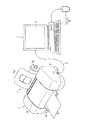
図1は、本実施の形態に係る印刷システムを示す概略図である。
印刷システムは、画像形成装置としてのパーソナルコンピュータ(以下「PC」という)1とプリンタ2とを含み、それらは、本実施の形態においては、例えばUSBケーブル3により接続されている。本実施形態では、プリンタ2はPC1の周辺機器として機能する。
DESCRIPTION OF THE PREFERRED EMBODIMENTS Embodiments embodying the present invention will be described below with reference to the drawings.
FIG. 1 is a schematic diagram showing a printing system according to the present embodiment.
The printing system includes a personal computer (hereinafter referred to as “PC”) 1 as an image forming apparatus and a printer 2, which are connected by, for example, a
PC1は、表示部としての表示画面4と操作部としての入力装置5とを備えており、ユーザは、表示画面4を見ながら、入力装置5を構成するキーボード5aやマウス5bを操作することで、印刷指示等の各種の指示をプリンタ2に与えることができる。
The
表示画面4は、画像データ(動画データ)や各種処理の結果を示す画面、用紙サイズ、用紙種類、レイアウト、静止画像選択、印刷枚数等のパラメータ入力等の表示に用いられる。そして、表示画面4に表示された種々の条件が入力装置5のキーボード5aやマウス5bの操作により選択されることで、プリンタ2に印刷指示等を与えることができるように構成されている。
The
表示画面4には、画面水平方向に800画素と画面垂直方向に600画素の表示エリアを備えており、ドットマトリクス状の画素で表現した画像データをRGBの三原色においてそれぞれ256階調表示することにより、約1670万色を表現可能となっている。なお、この解像度は一例に過ぎず、例えば、640×480画素や、1024×720画素に適宜変更可能である。
The
プリンタ2は、インクジェット式プリンタであり、本体6の背面側には用紙供給装置7が設けられており、シートフィーダ7aにセットされた用紙、あるいはロール紙支持部7bにセットされたロール紙等が本体6内部に給紙される。本体6の中央に設けられたカバー8の下方には印刷機構(図示略)が設けられており、この印刷機構の作動により印刷された用紙9が本体6の前側下部に設けられた排紙口10から排出される。
The printer 2 is an ink jet printer, and a
プリンタ2の本体6の側面下側には、外部機器と接続するための接続部として、本実施の形態においては例えばUSBポート11が設けられている。本実施形態では、USBポート11には、上述したようにプリンタ2がUSBケーブル3を介して接続されている。
In the present embodiment, for example, a USB port 11 is provided on the lower side of the side surface of the
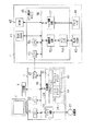
図2は、PC1及びそれに接続されるプリンタ2の構成を示すブロック図である。なお、図1と同様な構成部分については、同一符号を付して説明する。
まず、PC1の構成について説明する。
FIG. 2 is a block diagram showing the configuration of the
First, the configuration of the
PC1は、CPU21、メモリ22、記憶装置23、ドライブ装置24及びインタフェース回路(以下、単に「I/F」という)25を備え、それらは内部バス26を介して相互に接続されている。
The
制御部としてのCPU21は、記憶装置23に格納されているプログラムを読み出し、そのプログラムに従った処理を実行することにより、PC1を統括的に制御する。メモリ22は、CPU21が処理を実行する際のワーキングメモリとして利用される。
The
ドライブ装置24は、記録媒体27を駆動してその記憶内容にアクセスする。CPU21は、ドライブ装置24を介して記録媒体27からプログラムを読み出し、それを記憶装置23にインストールする。記憶装置23には、例えば、画像形成処理や、画像データをプリンタ2に送り出す処理等を実行するためのプログラムが格納されている。記録媒体27としては、光ディスク(CD-ROM,DVD-ROM,… )、光磁気ディスク(MO,MD,…)等、任意の記録媒体を使用することができる。なお、記録媒体27には、通信媒体を介してアップロード又はダウンロードされたプログラムを記録した媒体、ディスク装置を含む。
The
記憶装置23においては、PC1に画像データを入力するとともに、プリンタ2や表示画面4に画像データを出力するために所定のプログラムが実行される。そのうち、基本プログラムとして稼動しているのは、オペレーティングシステム(以下、「OS」という)31であり、このOS31上には、アプリケーションプログラム(以下、単に「アプリケーション」という)32が、記録媒体27としてのCD−ROMから読み取りをすることによりインストールされている。アプリケーション32にはディスプレイドライバ33やプリンタドライバ34等が組み込まれている。なお、ディスプレイドライバ33やプリンタドライバ34の類は、表示画面4やプリンタ2の機種に依存しており、それぞれの機種に応じてOS31に対して追加変更可能である。また、機種に依存して標準処理以上の付加機能を実現することもできるようになっており、許容される範囲内での各種の追加的処理を実現可能である。
In the
CPU21は、入力装置5の操作に基づいて、ドライブ装置24を介してDVD-ROM等の記録媒体27から画像データを読み込む処理や、画像データの加工をする処理、表示及び保存のための処理、画像データをディスプレイドライバ33に送って表示画面4に表示させる処理等を行う。
The
また、CPU21は、記録媒体27に記憶された動画データを順次読み出し、読み出した動画データをディスプレイドライバ33においてデコードし、該デコード後のデータを表示画面4に順次出力して動画を表示させる処理を行う。例えば、CPU21は、MPEG形式の動画データに対して復号化処理を施すことで、動画データをデコードし、それにより得られた多階調データをメモリ22に格納する。
The
そして、CPU21は、入力装置5の所定の操作ボタンが操作されると、動画の静止/再生を行う。詳しくは、動画の表示中に入力装置5が操作されると、動画を一時停止させて静止画像(フレーム)を表示させた状態とする。即ち、ディスプレイドライバ33は、メモリ22からの読み出し及びデコード処理を中断するとともに、その時にメモリ22に格納されているデコード済みのデータを表示画面4に繰り返し出力する。これにより、表示画面4には、動画を一時停止させた静止画像(フレーム)が表示される。そして、ディスプレイドライバ33は、動画の一時停止中に入力装置5が操作されると、静止画像以降の動画を再生する。
Then, when a predetermined operation button of the input device 5 is operated, the
また、CPU21は、動画から静止画像を取得する処理(キャプチャ処理)を実行する。CPU21は、メモリ22に記憶された動画データを表示画面4にて再生するとともに、入力装置5の操作によって連続的な再生を一時停止させ、表示画面4に表示されている画像のデータを入力装置5の操作によって参照フレームとする。そして、この参照フレームを基準として所定数のフレームを取得して画像合成に使用する複数のフレームとしてメモリ22に格納する。なお、このとき、CPU21はフレーム取得部に相当する。
In addition, the
そして、CPU21は、入力装置5の操作により印刷指令等の操作がなされると、メモリ22に格納された画像データ(画像合成に使用する複数のフレーム)をプリンタドライバ34に入力し、印刷データに変換させてプリンタ2に送出する処理を行う。
Then, when an operation such as a print command is performed by operating the input device 5, the
ここで、仮に、動画を表示画面4に表示させながら一時停止したときの1枚の静止画像を、プリンタ2において印刷画像として出力しようとすると、印刷画像に不具合が生じる場合がある。即ち、一般的な動画データを構成する1枚のフレームの画素数に対して、プリンタ2で出力される画像の画素密度が格段に多いため、1枚のフレームをプリンタ2において例えばL判用紙に印刷しようとすると、画素数の不足から良好な画質が得られない場合がある。また、表示画面4上での表示を画素単位で一致させて印刷するとなると極めて小さな画像となる場合がある。
Here, if one still image when paused while displaying a moving image on the
このため、本実施形態では、プリンタドライバ34は解像度変換処理を含む画像形成処理を実行する。つまり、プリンタドライバ34は、動画データを構成する複数のフレームを使用して、1枚のフレームの実際の画素の間に、該画素に基づいて副画素を生成する補間処理を行い、受け取った画像データの解像度をプリンタ2が印刷するための印刷解像度に変換する。
For this reason, in the present embodiment, the
また、プリンタドライバ34はコマンド生成部を備えており、コマンド生成部は解像度変換後にコマンドを付して印刷データとしてプリンタ2に出力する。I/F25は、USBケーブル3を介してプリンタ2と接続され、プリンタ2に印刷データを送信する。
In addition, the
次に、PC1と接続されたプリンタ2の構成について説明する。
プリンタ2は、シアン(C)、マゼンダ(M)、イエロー(Y)、ブラック(K)、ライトシアン(LC)、ライトマゼンダ(LM)、ライトイエロー(LY)の7色の色インクを用いて記録媒体たる用紙9上にドットを付して画像を印刷可能となっている。画像密度は、例えば、360×360dpiや720×720dpiといった高密度印刷が可能となっているが、階調表現については色インクを付すか否かといった2階調表現となっている。
Next, the configuration of the printer 2 connected to the
The printer 2 records using seven color inks of cyan (C), magenta (M), yellow (Y), black (K), light cyan (LC), light magenta (LM), and light yellow (LY). An image can be printed with dots added on the medium 9 as a medium. The image density is capable of high-density printing such as 360 × 360 dpi or 720 × 720 dpi, for example, but the gradation expression is a two-gradation expression such as whether or not color ink is applied.
上述したように、本実施形態においては、プリンタ2はPC1の周辺機器として機能する。プリンタ2は、第1のRAM41、ROM42、第2のRAM43、プリンタヘッド44及びCPU組込みASIC45を備えている。
As described above, in the present embodiment, the printer 2 functions as a peripheral device of the
第1のRAM41には、PC1から送られてきた画像データ(印刷データ等)が格納される。ROM42には、後述するCPU51が処理を実行するために必要な制御プログラムや各種のアプリケーションプログラムが格納されている。第2のRAM43は、後述するCPU51が処理を実行する際のワーキングメモリとして利用される。例えば、第2のRAM43は、後述する画像処理の段階で生成されるデータ(印刷イメージデータ等)を一時格納しておくためのバッファとして利用される。
The
プリンタヘッド44は、主走査方向(紙送り方向と垂直な方向)に往復移動するキャリッジ(図示略)の下端に設けられており、用紙9の搬送路に対向した面に各色のノズルを多数個有している。このプリンタヘッド44は、後述するヘッド制御回路52の制御に基づいて、主走査方向に往復移動しながら、各色のインク滴をそれぞれの色に対応したノズルから吐出することで、給紙された用紙9に画像を形成する。
The
CPU組込みASIC45は、CPU51、ヘッド制御回路52、画像処理回路53、メモリインタフェース回路(以下、単に「メモリI/F」という)54及びインタフェース回路(以下、単に「I/F」という)55を備え、それらは内部バス56にて相互に接続されている。この内部バス56には、上述した第1のRAM41及びROM42も接続されている。
The CPU embedded
CPU51は、ROM42に格納されているプログラムを読み出し、そのプログラムに従った処理を実行することにより、プリンタ2を統括的に制御する。例えば、CPU51には、後述する画像処理回路53での色変換処理、ハーフトーン処理及びマイクロウィーブ処理や、ヘッド制御回路52でのキャリッジのモータの駆動制御を司る。
The
画像処理回路53は、色変換部、ハーフトーニング部及びマイクロウィーブ部としての機能を有している。詳述すると、色変換部は、第1のRAM41に格納されているRGBの多階調の画像データに色変換処理を施し、例えば、シアン(C)、マゼンダ(M)、イエロー(Y)、ブラック(K)、ライトシアン(LC)、ライトマゼンダ(LM)、ライトイエロー(LY)の7色の多階調の画像データを生成して、それをメモリI/F54を介して接続された第2のRAM43に格納する。
The
ハーフトーニング部は、その色変換処理後の画像データにハーフトーン処理を施し、多階調の画像データを各色毎に2値化して表した印刷イメージデータ(色プレーン)を生成して、それを第2のRAM43に格納する。マイクロウィーブ部は、そのハーフトーン処理後の各色プレーンのラスタラインをノズル数、ヘッド走査回数、紙送り量等に基づき並び替えて印刷データを生成し、それらを第2のRAM43に格納する。
The halftoning unit performs halftone processing on the image data after the color conversion processing, generates print image data (color plane) representing the multi-tone image data binarized for each color, Stored in the
ヘッド制御回路52は、プリンタヘッド44を往復移動させるキャリッジのモータの駆動を制御するとともに、画像処理回路53で生成された各色の印刷データに基づいてインク滴の有無や、吐出するインク滴の量等を制御する。I/F55は、USBケーブル3を介してPC1と接続され、PC1から送られてくる画像データを受信する。
The
次に、上記の印刷システムにおいて実行される画像形成処理について説明する。
先ず、ユーザは、入力装置5を操作して、記録媒体27に記憶された動画データの選択画面を表示画面4に表示させて、所望の動画データD1を選択した後、入力装置5により動画再生の操作を行うと、図3に示す処理が開始される。
Next, an image forming process executed in the above printing system will be described.
First, the user operates the input device 5 to display the selection screen of the moving image data stored in the
ステップ100において、CPU21は、選択された動画データD1を記録媒体27から読み出し、その動画データD1をディスプレイドライバ33に転送する。ディスプレイドライバ33において、動画データD1がRGBの画像データにデコードされた後、該画像データが一旦メモリ22に格納される。CPU21は、その画像データに応じた静止画像(フレーム)を順次表示画面4に送出することで、表示画面4に動画を再生させる。
In
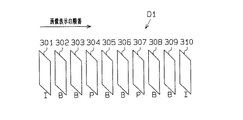
図4には、動画データD1を構成するフレームの具体例を示している。フレーム301〜310が図中矢印にて示す動画再生方向に順に表示されて動画が再生される。フレーム301,310はIピクチャーであり、フレーム内符号化により符号化されたフレームである。また、フレーム304,307はPピクチャーであり、直前のIピクチャー又はPピクチャーを参照画像とする片方向のフレーム間符号化により符号化されたフレームである。従って、例えばフレーム304を符号化する際には、フレーム301を参照してフレーム間予測が行われる。フレーム302,303,305,306,308,309はBピクチャーであり、直前と直後のIピクチャー又はPピクチャーを用いた双方向のフレーム間予測が行われる。なお、ディスプレイドライバ33は、Iピクチャー及びPピクチャーのみを表示画面4に表示させて、動画を高速で再生することも可能である。
FIG. 4 shows a specific example of the frames constituting the moving image data D1. The
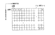
ステップ110において、CPU21は、アプリケーション32に、再生中の動画データD1から、画像合成に使用する複数のフレームを決定する処理を実行させる。即ち、CPU21は、表示画面4において再生中の動画データD1(図4参照)から静止画像(フレーム)を取得し、その静止画像を画像合成に使用する複数のフレームとして決定する。
In
また、このとき、CPU21は、ユーザによる操作部としての入力装置5の操作に応答して動画データD1の再生を一時停止させ、動画データD1の一時停止中に表示画面4に表示された画像を参照フレームF1とする。即ち、CPU21は、入力装置5から停止信号を取得し、表示画面4において再生中の動画データD1を一時停止させて、同じ静止画面(フレーム)を繰り返し表示させ、その状態で入力装置5から決定を指示する制御信号を取得すると、表示中の静止画像を参照フレームF1とする。
At this time, the
更に、CPU21は、参照フレームF1を基準に複数のフレームF2〜F4を取得して画像合成に使用する複数のフレームとする。具体的には、参照フレームF1を基準として、動画再生時に参照フレームF1の前に表示される1枚のフレームF2と、参照フレームF1の後に表示される2枚のフレームF3,F4とを取得する。そして、CPU21は、取得した参照フレームF1及びその他のフレームF2〜F4をメモリ22に格納する。
Further, the
このように、表示画面4に動画データD1を再生させながら一時停止の操作を行ったときに表示される画像が参照フレームF1として選択され、その参照フレームF1を基準としてその他のフレームF2〜F4が取得される。このため、ユーザは動画データD1の再生を一時停止させたときに表示画面4に表示された画像を確認し、その画像を高精細な合成画像として生成することができる。
Thus, the image displayed when the pause operation is performed while reproducing the moving image data D1 on the
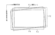
ステップ120において、CPU21は、アプリケーション32に、参照フレームF1とその他のフレームF2〜F4との間の動き量を検出する処理を実行させる。動画データD1を構成するフレーム間においては、図5に示すように、時間的な経過により多少のずれが存在する。
In step 120, the
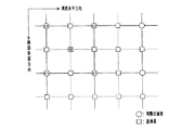
本実施形態では、所謂ブロックマッチング法を用いて、参照フレームF1とその他のフレームF2〜F4との間の動き量をそれぞれ検出する。具体的には、図6に示すように、各フレームF1〜F4の画面内は、画面水平方向8画素×画面垂直方向8画素単位のn個の小さなブロックに分割されるものとする。そして、各フレームにおいて、ブロック毎の画素値が計算され、各フレーム間において画素値の差分が最小となる領域が互いに相関が最も強いものとして検出される。そして、同じような画素値を有するブロックが画面の水平方向、垂直方向のどこにあるか検出され、このブロック位置のずれに基づいて参照フレームF1とその他のフレームF2〜F4との間の動き量がそれぞれ検出されてメモリ22に格納される。このように、ブロックマッチング法により動き量を検出することで、フレームF1〜F4間における小さなノイズまで確実に検出することができる。
In this embodiment, the amount of motion between the reference frame F1 and the other frames F2 to F4 is detected using a so-called block matching method. Specifically, as shown in FIG. 6, the screen of each of the frames F1 to F4 is divided into n small blocks of 8 pixels in the horizontal direction of the screen and 8 pixels in the vertical direction of the screen. Then, the pixel value for each block is calculated in each frame, and the region where the difference in pixel value between the frames is the smallest is detected as having the strongest correlation. Then, it is detected where the block having the same pixel value is in the horizontal direction and the vertical direction of the screen, and the amount of motion between the reference frame F1 and the other frames F2 to F4 is determined based on this block position shift. Each is detected and stored in the
なお、このとき、参照フレームF1とその他のフレームF2〜F4との間の平均的な動き量が全体的な動き量とされ、この全体的な動き量よりも大きい動き量を有する部分が局所部分画像D2として検出され、その位置情報とともにメモリ22に格納される。また、このとき、局所部分画像D2は、フレーム間において検出されただけ格納されるものである。
At this time, the average motion amount between the reference frame F1 and the other frames F2 to F4 is set as the overall motion amount, and a portion having a motion amount larger than the overall motion amount is a local portion. The image D2 is detected and stored in the
ステップ130において、CPU21は、アプリケーション32に、フレーム合成を行わせて中間画像を合成するとともに、枠画像を生成する処理を実行させる(第1の画像合成ステップ)。即ち、CPU21は、参照フレームF1及びフレームF2〜F4の画像データと、参照フレームF1と他のフレームF2〜F4との間の動き量のデータを取得し、それに基づいて参照フレームF1の画素間の副画素を生成して中間画像を生成する。
In
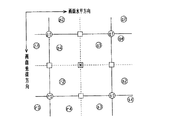
図7には、参照フレームF1における実際の画素(以下、単に「実画素」という)の位置と、実際の画素に基づき演算により算出される副画素の位置の一例を示している。実画素は、参照フレームF1の画面水平方向及び画面垂直方向にドットマトリックス状に配置されており、副画素は実画素の半分のピッチで配置されるように形成されている。例えば、図7に示す4つの実画素p1,q1,r1,s1に囲まれる箇所に副画素*が生成される際には、副画素*の画素値f(*)は、下記の式で表される。 FIG. 7 shows an example of the position of an actual pixel (hereinafter simply referred to as “real pixel”) in the reference frame F1 and the position of a sub-pixel calculated by calculation based on the actual pixel. The actual pixels are arranged in a dot matrix in the horizontal and vertical directions of the reference frame F1, and the sub-pixels are formed so as to be arranged at half the pitch of the actual pixels. For example, when a subpixel * is generated at a location surrounded by four real pixels p1, q1, r1, and s1 shown in FIG. 7, the pixel value f (*) of the subpixel * is expressed by the following equation. Is done.
f(*)=[f(p1)+f(q1)+f(r1)+f(s1)]/2
参照フレームF1とその他のフレームF2〜F4が重ねられると、図8に示すように、参照フレームF1の各実画素p1,q1,r1,s1の周囲にフレームF2〜F4の実画素が存在することとなる。そして、参照フレームF1に対する各フレームF2〜F4の動き量は検出されているため、参照フレームF1に重ねられたときのフレームF2の各実画素p2,q2,r2,s2の副画素*までの距離は検出される。また、同様に、参照フレームF1に重ねられたときのフレームF3の各実画素p3,q3,r3,s3の副画素*までの距離と、参照フレームF1に重ねられたときのフレームF4の各実画素p1,q1,r1,s1から副画素*までの距離は検出される。
f (*) = [f (p1) + f (q1) + f (r1) + f (s1)] / 2
When the reference frame F1 and the other frames F2 to F4 are overlapped, as shown in FIG. 8, the real pixels of the frames F2 to F4 exist around the real pixels p1, q1, r1, and s1 of the reference frame F1. It becomes. Since the motion amounts of the frames F2 to F4 with respect to the reference frame F1 are detected, the distances to the sub-pixels * of the actual pixels p2, q2, r2, and s2 of the frame F2 when superimposed on the reference frame F1 Is detected. Similarly, the distance to the sub-pixels * of the actual pixels p3, q3, r3, and s3 of the frame F3 when superimposed on the reference frame F1, and the actual values of the frame F4 when superimposed on the reference frame F1. The distances from the pixels p1, q1, r1, s1 to the subpixel * are detected.
このように、副画素*の周辺に存在することとなる実画素のそれぞれの距離が検出されるため、副画素*に最も近い位置にある4つの実画素を抽出し、それらの実画素の画素値と副画素*までの距離を用いることで、副画素*の画素値を算出することができる。このように、動画データD1を構成する複数のフレームF1〜F4を使用して実画素間の副画素を生成することで、高精度の合成画像を得ることができるようになる。 As described above, since the distances of the actual pixels existing around the subpixel * are detected, four real pixels that are closest to the subpixel * are extracted, and the pixels of those real pixels are extracted. By using the value and the distance to the subpixel *, the pixel value of the subpixel * can be calculated. In this way, a high-accuracy composite image can be obtained by generating subpixels between real pixels using a plurality of frames F1 to F4 constituting the moving image data D1.
ステップ140において、CPU21は、アプリケーション32に、ステップ130で合成された中間画像において、局所部分画像D2に対応する部分の画像を削除させる。このとき、メモリ22に記憶された、各フレームF1〜F4における局所部分画像D2の位置情報が読み出されて、中間画像上における各フレームF1〜F4の局所部分に対応する位置の画像が削除される。これは、中間画像合成時において、各フレームF1〜F4の局所部分画像D2に対応する位置の画像が破綻すると予測されるため、この領域を削除するものである。
In
ステップ150において、CPU21は、アプリケーション32に、各フレームF1〜F4の局所部分に対応する部分が削除された中間画像と、局所部分画像D2とを合成する処理を実行させる(第2の画像合成ステップ)。続いて、ステップ160において、CPU21は、アプリケーション32に、ステップ150にて生成された合成画像において、中間画像と局所部分画像D2との境界部分の平滑化処理を実行させて、境界処理画像としての印刷画像D3を合成する。そして、CPU21がアプリケーション32に、印刷画像D3のデータをI/F25に転送させた時点で本処理を終了する。
In
ここで、上述した画像形成処理を図9を参照して説明する。
動画データD1を構成するフレームの中から画像合成に使用すると決定された参照フレームF1とその他のフレームF2〜F4とがフレーム合成されて、中間画像501が生成される。このとき、参照フレームF1の実画素間の副画素が生成される(図8参照)。続いて、中間画像501において各フレームF1〜F4の局所部分に対応する削除部分501aが削除されて画像502が生成される。このように、複数のフレームF1〜F4を合成して中間画像501を生成してから削除部分501aを削除するため、画像に不具合が生じる部分を確認してから後述するはめ込み画像504を設定することが可能である。即ち、参照フレームF1とその他のフレームF2〜F4の間において、全体的な動き量に対して大きな動き量を有する局所部分が検出されたとしても、その局所部分に画像の乱れや破綻が生じるとは限らないし、予想以上に画像に不具合が生じる場合もある。このため、中間画像501を生成してから画像を削除することで、効率よく画像の合成処理を行うことができる。
Here, the above-described image forming process will be described with reference to FIG.
The reference frame F1 determined to be used for image synthesis from the frames constituting the moving image data D1 and the other frames F2 to F4 are frame-synthesized to generate an
一方、参照フレームF1において、局所部分画像503が抽出される。この局所部分画像503は、参照フレームF1とその他のフレームとF2〜F4の間においてそれぞれ検出される局所的な動きをする局所部分に基づいて設定される。つまり、参照フレームF1に対して各フレームF2〜F4において局所的な動きとなる局所部分を包括した部分が参照フレームF1において局所部分画像503とされる。このため、中間画像501において画像の破綻や乱れが生じる可能性が高い部分が加工されるようにはめ込み画像504の位置を設定することができる。
On the other hand, a local
更に、この局所部分画像503が拡大されて、はめ込み画像504が生成される。このとき、局所部分画像503の実際の画素間に副画素が生成されてはめ込み画像504が生成されるため(図7参照)、画像のムラや破綻が抑制されたはめ込み画像504が生成される。
Further, the local
そして、画像502に(即ち、削除部分501aが削除された中間画像501)にはめ込み画像504がはめ込まれ、合成画像505が合成される。その後、合成画像505において、画像502とはめ込み画像504との境界部分505aに平滑化処理が施されて、境界処理画像506が生成される。このように、画像502とはめ込み画像504との間に平滑化処理を施すことでこの部分の画像を滑らかにすることができ、画質を向上することができる。なお、この平滑化処理は、例えばガウシアンフィルタを用いて行われ、平滑化処理が行われる境界部分505aは、例えば、画像502とはめ込み画像504との間の境界線を中心として、動き検出時のブロックサイズ(図6参照)の1/4を半径とする範囲で適用させることで設定される。
Then, the embedded
次に、上述した画像形成処理の具体例を説明する。
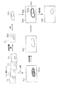
図10(a)に示す画像を参照フレームF1として画像を合成する場合、例えば図10(b)に示す画像がフレームF3として取得される。
Next, a specific example of the image forming process described above will be described.
When an image is synthesized using the image shown in FIG. 10A as a reference frame F1, for example, the image shown in FIG. 10B is acquired as a frame F3.
参照フレームF1とフレームF3とを比較すると、参照フレームF1とフレームF3との間の全体的な動き量M1に対して、局所的に大きな動き量M2を有する局所部分として、参照フレームにおける車Cが移動した車C2が存在している。なお、この車Cは、フレームF2,F4においても、フレーム間の動き量よりも大きい動き量で移動しているものとする。また、フレームF3においては、図中にノイズXが発生している。 Comparing the reference frame F1 and the frame F3, the vehicle C in the reference frame is a local portion having a locally large movement amount M2 with respect to the overall movement amount M1 between the reference frame F1 and the frame F3. A moved car C2 exists. It is assumed that the vehicle C is moving with a larger amount of motion than the amount of motion between frames in the frames F2 and F4. In the frame F3, noise X is generated in the figure.
すると、図10(c)に示すように、参照フレームF1とその他のフレームF2〜F4とを合成して中間画像501を生成すると(図9参照)、フレームF1〜F4において車Cが移動した範囲、即ち削除部分501aで画像が破綻してしまう。この削除部分501aの画像データが削除されて、参照フレームF1から削除部分501aに対応する部分の画像が抽出され拡大されて生成されたはめ込み画像が削除部分501aにはめ込まれる。
Then, as shown in FIG. 10C, when the
また、中間画像501においては、フレームF3に生じていたノイズXが合成されてノイズX´が生じている。
ノイズXは、参照フレームF1とフレームF3との間で動き量を検出する際に、局所的な動き量を有する局所部分として検出される。このため、中間画像501においてはノイズXの部分も削除部分501aとされ、この削除部分501aの画像データが削除されて、参照フレームF1から削除部分501aに対応する部分の画像が抽出され拡大されて生成されたはめ込み画像が削除部分501aにはめ込まれる。
In the
The noise X is detected as a local part having a local motion amount when detecting the motion amount between the reference frame F1 and the frame F3. Therefore, in the
以上記述したように、本実施形態によれば、以下の効果を奏する。
(1)本実施形態のPC1は、動画データD1を構成する複数のフレームF1〜F4を合成して合成画像505を生成するとき、複数のフレームF1〜F4に含まれる参照フレームF1の画素間に副画素を生成して中間画像501を生成し、中間画像501と参照フレームF1から抽出された画像により生成されたはめ込み画像504とを合成する。このように、中間画像501において、データのばらつきや不足に起因して画像の乱れや破綻等の不具合が生じる部分には、参照フレームF1から抽出された画像により生成されたはめ込み画像504がはめ込まれて合成されるため、この部分の画質を向上し高品質な合成画像505、ひいては境界処理画像506(印刷画像)を得ることができる。
As described above, according to the present embodiment, the following effects can be obtained.
(1) When the
(2)本実施形態のPC1は、中間画像501のはめ込み画像504に対応する削除部分501aが削除された画像502と、はめ込み画像504とを合成する。このように、中間画像501が合成されてから削除部分501aが削除されるため、削除部分501aに不具合が生じたことを確認してから、はめ込み画像504の位置を設定することができる。
(2) The
(3)本実施形態のPC1は、複数のフレームF1〜F4間の動き量を検出するとともにフレームF1〜F4間において局所的な動きをする局所部分を検出し、局所部分に基づいて参照フレームF1からはめ込み画像504を生成する。これにより、複数のフレームF1〜F4を合成する際に、画像の破綻を招く可能性の高い部分に対応する参照フレームF1の部分を抽出してはめ込み画像504を生成することができる。
(3) The
なお、実施の形態は、上記に限定されず以下の変形例を採用することもできる。
(変形例1)PC1は、複数のフレームを使用して画像を合成する際に、各フレームのはめ込み画像に対応する部分を削除してから中間画像を生成することとしてもよい。そうすると、中間画像が合成される前に、予め中間画像の合成に使用される各フレームのはめ込み画像に対応する部分が削除されるため、この部分については副画素の合成が行われず、不要な処理を省略することができる。
Note that the embodiment is not limited to the above, and the following modifications may be employed.
(Modification 1) When combining images using a plurality of frames, the
(変形例2)PC1は、局所部分の動き量を多段階に設定することとしてもよい。例えば、動き量の異なる局所部分が複数検出される場合に、動き量を多段階に設定することで、はめ込み画像をはめ込む局所部分を選択することが可能となる。
(Modification 2) The
(変形例3)PC1は、必ずしもブロックマッチング法により画像合成に使用する複数のフレームF1〜F4間の動き量を検出しなくてもよい。例えば、複数のフレームF1〜F4において特徴点を検出し、該特徴点の動き量を検出することで複数のフレームF1〜F4間の動き量を検出し、複数のフレームF1〜F4間における全体的な動き量よりも大きい動き量を有する部分を前記局所部分とすることとしてもよい。そうすると、画像の合成に使用される複数のフレームF1〜F4間の動き量は、各フレームF1〜F4において検出された特徴点のみを比較して検出されるため、フレーム内の全領域の画素の比較を行う場合と比較して、計算量が少なくてすみ画像形成処理を高速化することができる。
(Modification 3) The
(変形例4)上述した実施形態においては、複数のフレームF1〜F4を合成して中間画像501を生成するとき、4枚のフレームを重ねたときに副画素に最近接する4つの画素を用いて該副画素を生成するものとしたが、副画素を生成する手法はこれに限定されず、どのような手法により副画素を生成してもよい。
(Modification 4) In the embodiment described above, when the
(変形例5)PC1は、画像合成に使用するフレームを取得する際に、Iピクチャー又はPピクチャーを参照フレームとし、該参照フレームを基準に複数のフレームを取得してもよい。そうすると、動画データを構成するフレームのうちIピクチャー又はPピクチャーが参照フレームとされるため、表示画面4において動画データのIピクチャー又はPピクチャーのみを順次表示させる高速再生中に画像を選択することができるようになる。
(Modification 5) When acquiring a frame to be used for image synthesis, the
(変形例6)PC1は、複数のフレームF1〜F4を合成する際に、複数のフレームF1〜F4の画像をそれぞれ解析し、その解析結果に基づき画質がよいと判定されたフレームを合成することとしてもよい。そうすると、画質がよいと判定されたフレームのみを使用して画像が合成されるため、合成画像の画質を向上することができる。また、PC1は、フレーム間の動き量が大きい場合にはフレーム合成の際にそのフレームを使用しないようにしてもよい。
(Modification 6) When the
(変形例7)PC1は、必ずしも合成画像505の削除部分501aとはめ込み画像504との境界部分505aを平滑化処理しなくてもよい。
(変形例8)PC1は、中間画像501にはめ込み画像を合成する位置を設定する際に、必ずしも局所部分の動き量に基づいて設定しなくてもよい。例えば、確実に画像が破綻すると予想される位置を予めはめ込み画像の位置として設定しておいてもよい。
(Modification 7) The
(Modification 8) The
(変形例9)PC1は、参照フレームと3枚のフレームとを合成する場合に限定されず、参照フレームと1枚のフレームとを合成してもよいし、参照フレームと4枚以上のフレームとを合成してもよい。また、参照フレームF1を基準として画像合成に使用するフレームをどのように取得してもよく、例えば参照フレームF1を基準として後側のフレームのみを取得するようにしてもよい。
(Modification 9) The
(変形例10)PC1は、動画データD1を構成するフレームの中から、画像合成に使用するフレームをどのように取得してもよい。例えば、表示画面4に動画データD1を再生させながら、所定数毎に自動的に取得するようにしてもよい。
(Modification 10) The
(変形例11)上述した実施形態においては、PC1の画像入力デバイスとして、DVD-ROM 等の記録媒体27から動画データを入力する場合について説明したが、画像入力デバイスはこれに何ら限定されるものではない。例えば、PC1とデジタルスチルカメラやビデオカメラ、テレビ等とを接続し、それらのデバイスから動画データを取得するようにしてもよい。
(Modification 11) In the above-described embodiment, the case where moving image data is input from the
また、PC1に、外部のネットワークなどに接続するための通信デバイスとしてのモデムを接続し、外部のネットワークに同公衆通信回線を介して接続し、ソフトウェアやデータをダウンロードして導入するようにしてもよい。更には、モデムにて電話回線を介して外部にアクセスする形態に限定されず、例えばLANアダプタを介してネットワークに対してアクセスする構成とすることも可能である。
Further, a modem as a communication device for connecting to an external network or the like is connected to the
(変形例12)プリンタ2を画像形成装置とし、PC1を接続せずスタンドアロン型プリンタとして機能させてもよい。その場合、プリンタ2に動画データを再生可能な表示画面を装備した上で、上記実施形態で説明したプリンタドライバ34で実行される画像形成処理をプリンタ2の画像処理回路53に実行させるようにすればよい。そして、例えば、プリンタ2のUSBポート11にメモリカードが挿入されたデジタルスチルカメラやビデオカメラ等を接続し、表示画面に動画を再生させながら印刷画像を選択して印刷するようにしてもよい。また、プリンタ2にメモリカードを挿入可能なスロットを設け、そのメモリカードの動画データの画像を印刷するようにしてもよい。
(Modification 12) The printer 2 may be an image forming apparatus, and may function as a stand-alone printer without being connected to the
1…画像形成装置としてのパーソナルコンピュータ(PC)、2…プリンタ、4…表示部としての表示画面、5…操作部としての入力装置、21…制御部としてのCPU、34…第1の画像合成部及び第2の画像合成部としてのプリンタドライバ、301,310…Iピクチャー、304,307…Pピクチャー、501…中間画像、503…局所部分画像、504…はめ込み画像、505…合成画像、505a…境界部分、506…境界処理画像、F1…参照フレーム、F2,F3,F4…フレーム、M1…全体的な動き量、M2…局所的な動き量。
DESCRIPTION OF
Claims (15)
前記複数のフレームに含まれる参照フレームの画素間に副画素を生成して中間画像を生成する第1の画像合成部と、
前記中間画像と前記参照フレームから抽出された画像により生成されたはめ込み画像とを合成する第2の画像合成部と、
を備えた画像形成装置。 In an image forming apparatus that generates a composite image by combining a plurality of frames constituting moving image data,
A first image synthesizing unit that generates a sub-pixel between pixels of a reference frame included in the plurality of frames to generate an intermediate image;
A second image synthesizing unit that synthesizes the intermediate image and the inset image generated by the image extracted from the reference frame;
An image forming apparatus.
前記第2の画像合成部は、前記中間画像の前記はめ込み画像に対応する部分が削除された画像と、前記はめ込み画像とを合成する画像形成装置。 The image forming apparatus according to claim 1.
The second image composition unit is an image forming device that composes an image from which the portion corresponding to the embedded image of the intermediate image is deleted and the embedded image.
前記第1の画像合成部は、前記複数のフレームの前記はめ込み画像に対応する部分を削除してから前記中間画像を生成する画像形成装置。 The image forming apparatus according to claim 1.
The first image composition unit is an image forming apparatus that generates the intermediate image after deleting a portion corresponding to the inset image of the plurality of frames.
前記第2の画像合成部は、前記中間画像と前記はめ込み画像との境界部分に平滑化処理を施して境界処理画像を生成する画像形成装置。 The image forming apparatus according to any one of claims 1 to 3,
The second image composition unit is an image forming apparatus that generates a boundary-processed image by performing a smoothing process on a boundary portion between the intermediate image and the fitted image.
前記第1の画像合成部は、前記複数のフレーム間の動き量を検出するとともに、同複数のフレーム間において局所的な動きをする局所部分を検出し、前記第2の画像合成部は、前記局所部分に基づいて前記参照フレームから前記はめ込み画像を生成する画像形成装置。 The image forming apparatus according to any one of claims 1 to 4,
The first image synthesizing unit detects a motion amount between the plurality of frames, detects a local portion that performs a local motion between the plurality of frames, and the second image synthesizing unit includes: An image forming apparatus that generates the inset image from the reference frame based on a local portion.
前記第1の画像合成部は、ブロックマッチング法により前記複数のフレーム間の動き量を検出し、前記複数のフレーム間における全体的な動き量よりも大きい動き量を有する部分を前記局所部分とする画像形成装置。 The image forming apparatus according to claim 5.
The first image composition unit detects a motion amount between the plurality of frames by a block matching method, and a portion having a motion amount larger than an overall motion amount between the plurality of frames is set as the local portion. Image forming apparatus.
前記第1の画像合成部は、前記複数のフレームにおいて特徴点を検出し、該特徴点の動き量を検出することで前記複数のフレーム間の動き量を検出し、前記複数のフレーム間における全体的な動き量よりも大きい動き量を有する部分を前記局所部分とする画像形成装置。 The image forming apparatus according to claim 5.
The first image synthesizing unit detects feature points in the plurality of frames, detects a motion amount of the feature points, detects a motion amount between the plurality of frames, and performs an entire process between the plurality of frames. An image forming apparatus in which a portion having a larger amount of motion than a typical amount of motion is used as the local portion.
前記第1の画像合成部は、前記局所部分の動き量を多段階に設定する画像形成装置。 The image forming apparatus according to any one of claims 5 to 7,
The first image composition unit is an image forming apparatus that sets the amount of motion of the local portion in multiple stages.
前記第1の画像合成部は、前記参照フレームと2枚以上のフレームとを合成し、前記参照フレームとその他のフレームとの間においてそれぞれ検出される局所的な動きをする部分に基づいて前記局所部分を設定する画像形成装置。 The image forming apparatus according to any one of claims 5 to 8,
The first image synthesizing unit synthesizes the reference frame and two or more frames, and the local image based on a portion that performs a local motion detected between the reference frame and another frame. An image forming apparatus for setting a part.
表示部において再生中の動画データから静止画像を取得し、該静止画像を前記複数のフレームとするフレーム取得部を備えた画像形成装置。 The image forming apparatus according to any one of claims 1 to 9,
An image forming apparatus including a frame acquisition unit that acquires a still image from moving image data being reproduced on a display unit and uses the still image as the plurality of frames.
前記フレーム取得部は、操作部の操作に応答して前記動画データの再生を一時停止させ、前記動画データの一時停止中に前記表示部に表示された画像を前記参照フレームとし、該参照フレームを基準に複数のフレームを取得して前記複数のフレームとする画像形成装置。 The image forming apparatus according to claim 10.
The frame acquisition unit pauses the reproduction of the moving image data in response to an operation of the operation unit, sets the image displayed on the display unit during the suspension of the moving image data as the reference frame, and uses the reference frame as a reference frame. An image forming apparatus that obtains a plurality of frames as a reference and uses the frames as the plurality of frames.
前記フレーム取得部は、Iピクチャー又はPピクチャーを前記参照フレームとし、該参照フレームを基準に複数のフレームを取得して前記複数のフレームとする画像形成装置。 The image forming apparatus according to claim 10.
The frame acquisition unit is an image forming apparatus in which an I picture or a P picture is used as the reference frame, and a plurality of frames are acquired based on the reference frame to form the plurality of frames.
前記第1の画像合成部は、前記複数のフレームの画像をそれぞれ解析し、その解析結果に基づき画質がよいと判定されたフレームを合成する画像形成装置。 The image forming apparatus according to any one of claims 1 to 12,
The first image composition unit analyzes each of the images of the plurality of frames, and synthesizes frames determined to have good image quality based on the analysis result.
前記複数のフレームに含まれる参照フレームの画素間に副画素を生成して中間画像を生成する第1の画像合成ステップと、
前記中間画像と前記参照フレームから抽出された画像により生成されたはめ込み画像とを合成する第2の画像合成ステップと、
を備えた画像形成方法。 In an image forming method for generating a composite image by combining a plurality of frames constituting video data,
A first image synthesis step of generating an intermediate image by generating a sub-pixel between pixels of a reference frame included in the plurality of frames;
A second image synthesis step of synthesizing the intermediate image and an inset image generated by an image extracted from the reference frame;
An image forming method.
前記制御部が、
前記複数のフレームに含まれる参照フレームの画素間に副画素を生成して中間画像を生成する第1の画像合成処理と、
前記中間画像と前記参照フレームから抽出された画像により生成されたはめ込み画像とを合成する第2の画像合成処理と、
を実行するための画像形成プログラム。 An image forming program for the control unit to execute a process of generating a composite image by combining a plurality of frames constituting moving image data,
The control unit is
A first image composition process for generating an intermediate image by generating a sub-pixel between pixels of a reference frame included in the plurality of frames;
A second image synthesis process for synthesizing the intermediate image and an inset image generated by an image extracted from the reference frame;
An image forming program for executing.
Priority Applications (1)
| Application Number | Priority Date | Filing Date | Title |
|---|---|---|---|
| JP2004096486A JP2005284635A (en) | 2004-03-29 | 2004-03-29 | Image forming apparatus, image forming method, and image forming program |
Applications Claiming Priority (1)
| Application Number | Priority Date | Filing Date | Title |
|---|---|---|---|
| JP2004096486A JP2005284635A (en) | 2004-03-29 | 2004-03-29 | Image forming apparatus, image forming method, and image forming program |
Publications (1)
| Publication Number | Publication Date |
|---|---|
| JP2005284635A true JP2005284635A (en) | 2005-10-13 |
Family
ID=35182951
Family Applications (1)
| Application Number | Title | Priority Date | Filing Date |
|---|---|---|---|
| JP2004096486A Pending JP2005284635A (en) | 2004-03-29 | 2004-03-29 | Image forming apparatus, image forming method, and image forming program |
Country Status (1)
| Country | Link |
|---|---|
| JP (1) | JP2005284635A (en) |
Cited By (8)
| Publication number | Priority date | Publication date | Assignee | Title |
|---|---|---|---|---|
| JP2007000205A (en) * | 2005-06-21 | 2007-01-11 | Sanyo Electric Co Ltd | Image processing apparatus, image processing method, and image processing program |
| WO2007102377A1 (en) * | 2006-03-03 | 2007-09-13 | Olympus Corporation | Imaging device, processing method for obtaining high-resolution, processing program for obtaining high-resolution, and recording medium |
| JP2008109375A (en) * | 2006-10-25 | 2008-05-08 | Tokyo Institute Of Technology | High resolution image generation method |
| JP2008301043A (en) * | 2007-05-30 | 2008-12-11 | Fujitsu Ltd | Image composition apparatus, image composition method, and image composition program |
| JP2008310418A (en) * | 2007-06-12 | 2008-12-25 | Nikon Corp | Image processing apparatus, image processing program, and electronic camera equipped with the same |
| JP2009093676A (en) * | 2009-01-19 | 2009-04-30 | Sony Corp | Image processing apparatus, image processing method, and program |
| US8036488B2 (en) | 2006-11-30 | 2011-10-11 | Sony Corporation | Image processing apparatus, image processing method and program |
| JP2019046149A (en) * | 2017-09-01 | 2019-03-22 | コニカミノルタ株式会社 | Crop cultivation support apparatus |
-
2004
- 2004-03-29 JP JP2004096486A patent/JP2005284635A/en active Pending
Cited By (12)
| Publication number | Priority date | Publication date | Assignee | Title |
|---|---|---|---|---|
| JP2007000205A (en) * | 2005-06-21 | 2007-01-11 | Sanyo Electric Co Ltd | Image processing apparatus, image processing method, and image processing program |
| WO2007102377A1 (en) * | 2006-03-03 | 2007-09-13 | Olympus Corporation | Imaging device, processing method for obtaining high-resolution, processing program for obtaining high-resolution, and recording medium |
| US7978234B2 (en) | 2006-03-03 | 2011-07-12 | Olympus Corporation | Image acquisition apparatus, resolution enhancing method, and recording medium |
| JP2008109375A (en) * | 2006-10-25 | 2008-05-08 | Tokyo Institute Of Technology | High resolution image generation method |
| US8036488B2 (en) | 2006-11-30 | 2011-10-11 | Sony Corporation | Image processing apparatus, image processing method and program |
| US8346012B2 (en) | 2006-11-30 | 2013-01-01 | Sony Corporation | Image processing apparatus, image processing method and program |
| KR101421624B1 (en) | 2006-11-30 | 2014-07-22 | 소니 주식회사 | Image processing apparatus, image processing method and program |
| JP2008301043A (en) * | 2007-05-30 | 2008-12-11 | Fujitsu Ltd | Image composition apparatus, image composition method, and image composition program |
| JP2008310418A (en) * | 2007-06-12 | 2008-12-25 | Nikon Corp | Image processing apparatus, image processing program, and electronic camera equipped with the same |
| JP2009093676A (en) * | 2009-01-19 | 2009-04-30 | Sony Corp | Image processing apparatus, image processing method, and program |
| JP2019046149A (en) * | 2017-09-01 | 2019-03-22 | コニカミノルタ株式会社 | Crop cultivation support apparatus |
| JP7069609B2 (en) | 2017-09-01 | 2022-05-18 | コニカミノルタ株式会社 | Crop cultivation support device |
Similar Documents
| Publication | Publication Date | Title |
|---|---|---|
| JP4975002B2 (en) | Image processing apparatus, image forming apparatus, and image processing method | |
| JP2002185789A (en) | Image processing apparatus, print control apparatus, image processing method, and recording medium | |
| JP2009262457A (en) | Image forming apparatus and image forming method | |
| JP6769045B2 (en) | Image processing equipment and computer programs | |
| JP2005284635A (en) | Image forming apparatus, image forming method, and image forming program | |
| JP7653808B2 (en) | Information processing device, program, and image processing method | |
| JP6184115B2 (en) | Image processing method and image processing apparatus | |
| US6243174B1 (en) | Image processing device, color printing device, image processing method and medium recording image processing program | |
| KR102357562B1 (en) | Image forming apparatus capable of undergoing remote image diagnosis, control method therefor, and storage medium storing control program therefor | |
| JP2010147935A (en) | Image processing apparatus and image processing method | |
| US20090201520A1 (en) | Image Processing for Determining Dot Formation States in Printing an Image | |
| JP2003048340A (en) | Printing to suppress contour blur | |
| JP2005284636A (en) | Motion amount detection apparatus, image forming apparatus, motion amount detection method, and motion amount detection program | |
| JP2005286612A (en) | Image forming apparatus, image forming method, and image forming program | |
| JPH1095141A (en) | Image recording device | |
| JP2003244469A (en) | Image deciding apparatus, image reader, image deciding method, program and storage medium stored with program | |
| JP2006014039A (en) | An image output system that outputs images while performing multi-value conversion for each pixel. | |
| US7362473B2 (en) | Image processing technique for tone number conversion of image data | |
| JP2004088251A (en) | Image processing apparatus, method, program for executing the method, and recording medium | |
| JP2001186366A (en) | Image processing method, apparatus and recording medium | |
| US8279478B2 (en) | Printing system, printing apparatus and image-printing method for suppressing image quality degradation | |
| US8170344B2 (en) | Image storage device, image storage system, method of storing image data, and computer program product for image data storing | |
| JP2007088912A (en) | Image processing apparatus and program | |
| EP2571244A2 (en) | Image processing apparatus, method, image forming apparatus, and storage medium | |
| JP4100522B2 (en) | Image processing apparatus, image processing method, and recording medium recording the program |