JP2005283966A - Lens system for projection and projector device - Google Patents
Lens system for projection and projector device Download PDFInfo
- Publication number
- JP2005283966A JP2005283966A JP2004097850A JP2004097850A JP2005283966A JP 2005283966 A JP2005283966 A JP 2005283966A JP 2004097850 A JP2004097850 A JP 2004097850A JP 2004097850 A JP2004097850 A JP 2004097850A JP 2005283966 A JP2005283966 A JP 2005283966A
- Authority
- JP
- Japan
- Prior art keywords
- lens
- lens system
- projection
- negative
- screen
- Prior art date
- Legal status (The legal status is an assumption and is not a legal conclusion. Google has not performed a legal analysis and makes no representation as to the accuracy of the status listed.)
- Pending
Links
Images


Classifications
-
- G—PHYSICS
- G02—OPTICS
- G02B—OPTICAL ELEMENTS, SYSTEMS OR APPARATUS
- G02B13/00—Optical objectives specially designed for the purposes specified below
- G02B13/18—Optical objectives specially designed for the purposes specified below with lenses having one or more non-spherical faces, e.g. for reducing geometrical aberration
-
- G—PHYSICS
- G02—OPTICS
- G02B—OPTICAL ELEMENTS, SYSTEMS OR APPARATUS
- G02B13/00—Optical objectives specially designed for the purposes specified below
- G02B13/16—Optical objectives specially designed for the purposes specified below for use in conjunction with image converters or intensifiers, or for use with projectors, e.g. objectives for projection TV
Landscapes
- Physics & Mathematics (AREA)
- General Physics & Mathematics (AREA)
- Optics & Photonics (AREA)
- Lenses (AREA)
- Projection Apparatus (AREA)
Abstract
Description
本発明は、液晶あるいはDMDといったライトバルブに表示された像をスクリーンに拡大投影するプロジェクタ装置の投写用レンズシステムに関するものである。 The present invention relates to a projection lens system for a projector apparatus that enlarges and projects an image displayed on a light valve such as liquid crystal or DMD onto a screen.
特開2002−357769号公報には、プロジェクタ装置に用いる投写レンズ装置について、一対のプラスチック製の非球面レンズを用いることが開示されている。さらに、前側の非球面レンズは負パワーとし、後側の非球面レンズは正パワーとし、プラスチック製のレンズが熱で変形し、屈折率が変化した場合、正パワーのレンズと負パワーのレンズとで影響を打ち消しあい、収差を補正する性能の低下を抑制することが記載されている。
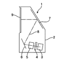
レンズシステムにおいて、少ない枚数のレンズにより収差を高いレベルで補正するために、非球面レンズを導入することが多い。非球面レンズはガラス製のレンズでも実現できるが、コストと、加工が容易であることからプラスチック製のレンズが用いられることが多い。しかしながら、プラスチック製のレンズは熱膨張係数が大きいので、熱による形状の変化が逆に収差性能を低下する要因になる。特に、図1に示すようなリアプロジェクタにおいては、投写用のレンズシステムが完全にクローズされた環境に配置されるので、レンズシステムの少なくとも一部が露出する従来のスクリーンとプロジェクタが分離したプロジェクタシステムと比較すると熱の影響を受けやすい。図1に示したリアプロジェクタ1は、ハウジング2の内部に、光源3と、光源3からの光を画像信号により変調して画像を形成する光変調器(ライトバルブ)4と、ライトバルブ4からの投影光8をスクリーン9に背面から投写する投写用レンズシステム5と、投影光8を反射してスクリーン9に導くミラー6および7を備えている。光源3とライトバルブ4が一体になったCRTが用いられるケースもあるが、近年においては、ライトバルブ4として液晶パネルが多く採用されており、さらに、上述したマイクロミラー素子によりDMDパネルも採用されることがある。DMDパネルの場合は、ライトバルブ4が反射型となるために光源3との位置関係が図1に示したものと異なるが、液晶パネルおよびDMDパネルをライトバルブ4とする場合は、レンズシステム5の入力側はテレセントリックとなる。したがって、入力側がテレセントリックで、変調光(投影光)8を拡大投影する投写用レンズシステム5が要求される。
In a lens system, an aspheric lens is often introduced in order to correct aberrations at a high level with a small number of lenses. An aspherical lens can be realized by a glass lens, but a plastic lens is often used because of its cost and easy processing. However, since a plastic lens has a large thermal expansion coefficient, a change in shape due to heat causes a decrease in aberration performance. In particular, in the rear projector as shown in FIG. 1, since the lens system for projection is disposed in a completely closed environment, the projector system in which at least a part of the lens system is exposed and the conventional screen separated from the projector is provided. Is more susceptible to heat than A
非球面の精度を考慮すると、非球面化する面積が大きい方が収差を補正するのに適した面を形成しやすい。しかしながら、非球面レンズのレンズ径を大きくすることは、ガラス製のレンズであれば、非常なコストアップになり、プラスチック製のレンズであれば、熱変形による影響が大きくなるというディメリットがある。このため、投写用のレンズシステムでは、最もスクリーン側のレンズ径が最大になるが、特開2002−357769号公報に開示されているように、最もスクリーン側のレンズではなく、次のレンズあるいは、中間に位置するレンズを非球面にすることが多い。もっとも、レンズシステムを構成するレンズ枚数が数枚という極めて簡易な構成のレンズシステムでは、非球面を導入可能な面が限られるので、最もスクリーン側のレンズ径が最も大きくなるレンズの一方の面あるいは両方の面を非球面化することがある。この簡易な構成のレンズシステムの場合、従来のスクリーンとセパレートされたプロジェクタであれば、最もスクリーン側のレンズは熱影響が最も少ないレンズであり熱変形も少なく、また、簡易なシステムであることを前提として収差補正能力もそれほど高いものが要求されないので、非球面レンズには熱変形してもレンズシステム全体の収差能力にはそれほどの影響が現れない程度の補正能力しか持たせていない。 In consideration of the accuracy of the aspheric surface, it is easier to form a surface suitable for correcting the aberration when the aspheric surface is larger. However, enlarging the lens diameter of the aspherical lens has a demerit that if the lens is made of glass, the cost is increased, and if the lens is made of plastic, the influence of thermal deformation is increased. For this reason, in the lens system for projection, the lens diameter on the most screen side is the largest, but as disclosed in JP-A-2002-357769, the following lens or In many cases, an intermediate lens is aspherical. However, in a lens system having a very simple configuration in which the number of lenses constituting the lens system is several, the number of surfaces on which the aspherical surface can be introduced is limited. Both surfaces may be aspherical. In the case of this simple lens system, if the projector is separated from the conventional screen, the lens on the most screen side is the lens that has the least thermal influence and little thermal deformation, and that it is a simple system. Since it is not required that the aberration correction capability is so high as a premise, the aspherical lens has only a correction capability that does not affect the aberration capability of the entire lens system even if it is thermally deformed.
しかしながら、今後登場するリアプロジェクタにおいては、レンズシステムが設置される条件により熱による影響は従来のプロジェクタより遥かに大きい。また、画質は現在のブラウン管あるいは液晶テレビと同等あるいはそれ以上のものが要求される。さらに、低コストであることは常に要求されることである。特開2002−357769号公報に開示されているように非球面レンズの熱変形の影響を、非球面レンズを増やすことで解決する方法は、非球面の設計および製造に必要なコストが増加し、さらに、増加した非球面の熱変形により収差能力が低下しないようにするためには設計精度を向上し、製造の歩留まりを高くする必要があるので、その点でも高コストになる。 However, rear projectors that will appear in the future are much more affected by heat than conventional projectors depending on the conditions under which the lens system is installed. Also, the image quality is required to be equal to or higher than that of the current cathode ray tube or liquid crystal television. In addition, low cost is always required. As disclosed in JP-A-2002-357769, a method for solving the influence of thermal deformation of an aspheric lens by increasing the number of aspheric lenses increases the cost required for designing and manufacturing the aspheric surface, Furthermore, it is necessary to improve the design accuracy and increase the manufacturing yield in order to prevent the aberration ability from being lowered due to the increased thermal deformation of the aspherical surface.
そこで、本発明においては、収差補正能力が高く、さらに、熱による収差補正能力の低下を抑制でき、低コストで供給できる投写用レンズを提供することを目的としている。 Accordingly, an object of the present invention is to provide a projection lens that has a high aberration correction capability, can suppress a decrease in aberration correction capability due to heat, and can be supplied at low cost.
このため、本発明においては、光変調器からの投影光をスクリーンに投写する投写用レンズシステムであって、入射側がテレセントリックであり、最もスクリーン側に配置されたスクリーン側に凸の第1のメニスカスレンズと、次に配置されたスクリーン側に凸の第2のメニスカスレンズとを有する、最もスクリーン側のレンズ群が多数枚で構成されるようなレンズシステムにおいて、第1のメニスカスレンズを、プラスチック製で、その両曲面の少なくとも一方の面は非球面の非球面レンズとし、さらに、第1のメニスカスレンズの屈折力が第2のメニスカスレンズの屈折力よりも小さいパワー配分としている。このようなパワー配分の構成では、第1のメニスカスレンズの両曲面の近軸曲率半径を、次の第2のメニスカスレンズのスクリーン側の面の曲率半径よりも大きくした方がレンズ配置の自由度が高い。 Therefore, according to the present invention, there is provided a projection lens system for projecting the projection light from the light modulator onto the screen, wherein the incident side is telecentric, and the first meniscus convex on the screen side disposed closest to the screen side. In a lens system having a lens and a second meniscus lens convex on the screen side, which is arranged next, the lens group on the most screen side is composed of a plurality of lenses, the first meniscus lens is made of plastic Thus, at least one of the two curved surfaces is an aspherical aspheric lens, and the power distribution of the first meniscus lens is smaller than the refractive power of the second meniscus lens. In such a power distribution configuration, the degree of freedom in lens arrangement is greater when the paraxial radius of curvature of both curved surfaces of the first meniscus lens is larger than the radius of curvature of the screen side surface of the next second meniscus lens. Is expensive.
従来のレンズシステムの設計では、レンズシステムを構成する各レンズのパワー配分を所望の収差性能あるいはそれに近い収差性能が得られるようにした後、いずれかの面を非球面にしてさらに収差を補正する能力が向上するようにしている。このため、非球面化しようとするプラスチックレンズも、レンズシステムを構成する上で重要なパワーを備えたものとなり、レンズシステムの収差補正能力に対するプラスチックレンズの熱変形の影響は、パワーの変動と非球面の変形とが相乗された状態で作用する。 In the conventional lens system design, the power distribution of each lens constituting the lens system is set so as to obtain a desired aberration performance or an aberration performance close thereto, and then any surface is aspherical to further correct aberrations. I try to improve my ability. For this reason, the plastic lens to be aspherical also has an important power in constructing the lens system, and the influence of the thermal deformation of the plastic lens on the aberration correction capability of the lens system is caused by the fluctuation of power and non-magnification. It works in a state where the deformation of the spherical surface is synergistic.
これに対し、本発明の投写用レンズシステムにおいては、第1のメニスカスレンズの基本的な屈折力を他のレンズに対して弱くしている。その上で、その第1のメニスカスレンズの両曲面あるいは一方の曲面を非球面化して収差補正能力を与えている。すなわち、本発明の投写用レンズシステムは、各レンズのパワー配分に対して、非球面化することを優先して設計されており、第1のメニスカスレンズにはパワーをほとんど配分せずに非球面にすることを基本として設計している。 On the other hand, in the projection lens system of the present invention, the basic refractive power of the first meniscus lens is weaker than other lenses. After that, both the curved surfaces or one of the curved surfaces of the first meniscus lens are aspherical to provide aberration correction capability. That is, the projection lens system of the present invention is designed with priority given to aspherical power distribution with respect to the power distribution of each lens, and the first meniscus lens is aspherical with almost no power distribution. It is designed to be based on.
液晶やDMDといったライトバルブからの投影光をスクリーンに投影する投写用レンズシステムにおいては、入射側をバックフォーカスの長いテレセントリックとなるように設計し、さらに、最も口径が大きくなる最もスクリーン側の第1のレンズの径を小さくするために、その第1のレンズを負の屈折力のメニスカスレンズにより構成することが多く、最もスクリーン側のレンズの屈折力を大きくして、コンパクトで画角の大きなレンズシステムとする設計が採用されている。したがって、従来、第1のレンズを非球面にすることは諸収差の補正能力に熱変形の影響が大きく表れることを意味しており、第1のレンズの後方に非球面のレンズを配置している。 In a projection lens system that projects projection light from a light valve such as liquid crystal or DMD onto a screen, the incident side is designed to be telecentric with a long back focus, and further, the first on the most screen side where the aperture is the largest. In order to reduce the diameter of the lens, the first lens is often composed of a meniscus lens having a negative refractive power. The system design is adopted. Therefore, conventionally, making the first lens an aspherical surface means that the effect of thermal deformation appears greatly on the correction capability of various aberrations. An aspherical lens is disposed behind the first lens. Yes.
しかしながら、本発明の投写用レンズシステムのように、両面が同じ方向の曲率半径を有するメニスカスレンズであり、負の屈折力のレンズであれば、その屈折力を小さくすることにより、曲面を維持しながらレンズの中心厚と周辺厚との差が少なくなる。このため、メニスカスレンズの屈折力を小さくすることにより、熱変形による屈折力の分布の変動は小さくなり、第1のメニスカスレンズのような径の大きなレンズであっても非球面の変形による収差補正能力の低下も少なくなる。 However, as in the projection lens system of the present invention, if both surfaces are meniscus lenses having the same radius of curvature and have a negative refractive power, the curved surface can be maintained by reducing the refractive power. However, the difference between the center thickness of the lens and the peripheral thickness is reduced. For this reason, by reducing the refractive power of the meniscus lens, the fluctuation of the refractive power distribution due to thermal deformation is reduced, and even with a large diameter lens such as the first meniscus lens, aberration correction due to aspherical deformation. The decrease in ability is also reduced.
そして、最もスクリーン側の第1のメニスカスレンズは、口径が最も大きなレンズであり、収差を補正するのに適した形状の非球面を設計し、加工することが容易なので、収差補正のために非球面化するのに適しているレンズであるというメリットをもたらす。したがって、本発明により、収差補正に適したレンズを非球面化でき、さらに、そのレンズの熱変形による影響を抑制できる。また、径の大きな第1のメニスカスレンズであれば、屈折力が小さくても収差を補正するのに十分な形状の非球面を形成することができるので、第1のメニスカスレンズを、パワーが小さくてもレンズシステムの収差補正能力に対して十分に寄与するように設計することができる。 The first meniscus lens on the most screen side is the lens having the largest aperture, and it is easy to design and process an aspherical surface having a shape suitable for correcting aberrations. This provides the advantage of being a lens suitable for spheroidization. Therefore, according to the present invention, a lens suitable for aberration correction can be aspherical, and the influence of thermal deformation of the lens can be suppressed. In addition, since the first meniscus lens having a large diameter can form an aspherical surface having a sufficient shape to correct aberrations even when the refractive power is small, the first meniscus lens has a small power. However, it can be designed to contribute sufficiently to the aberration correction capability of the lens system.
例えば、第1および第2のメニスカスレンズも含めて、スクリーン側より、負−負−負−正−負−正−正―負−正−正−正の11枚構成の投写用レンズシステムにおいては、第1のメニスカスレンズのみを非球面レンズとすることにより、上記にて特許文献1に示した特開2002−357769号公報の11枚構成で非球面レンズを2枚含んだレンズシステムより高い結像性能を得ることができる。
For example, in a projection lens system including eleven lenses of negative-negative-negative-positive-negative-positive-positive-negative-positive-positive-positive from the screen side including the first and second meniscus lenses. By using only the first meniscus lens as an aspheric lens, the lens system including the two aspheric lenses in the 11-sheet configuration disclosed in Japanese Patent Application Laid-Open No. 2002-357769 shown in
このように、レンズシステムのパワー配分に優先して、第1のメニスカスレンズのパワーを低くして非球面化することにより、全体の収差補正性能に対する非球面レンズの熱影響を抑制することが可能となる。したがって、非球面レンズの熱影響を抑制するために、余分な非球面レンズを導入して設計および製造にかかる費用を増加する必要もない。このため、本発明により、非球面を用いることにより収差補正能力が高く、さらに、熱による収差補正能力の低下が少ない投写用レンズシステムを低コストで供給できる。 In this way, the influence of the aspherical lens on the overall aberration correction performance can be suppressed by lowering the power of the first meniscus lens and making it aspherical in preference to the power distribution of the lens system. It becomes. Therefore, in order to suppress the thermal effect of the aspherical lens, it is not necessary to introduce an extra aspherical lens to increase the design and manufacturing costs. Therefore, according to the present invention, it is possible to supply a low-cost projection lens system that has high aberration correction capability by using an aspherical surface and that further reduces deterioration in aberration correction capability due to heat.
したがって、本発明の投写用レンズシステムと、光変調器とを有するプロジェクタ装置により、リアプロジェクタのようなレンズシステム全体が高温になりやすいアレンジの装置であっても、高画質の画像を安定して表示することができる。 Therefore, the projector apparatus having the projection lens system of the present invention and the light modulator can stably provide a high-quality image even in an arrangement apparatus in which the entire lens system such as a rear projector tends to be hot. Can be displayed.
(第1の実施例)
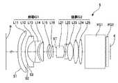
図2に本発明の投写用レンズシステム5のレンズ配置を示してある。本例の投写用レンズシステム5は、スクリーン9の側(出力側)からライトバルブ4(入力側)に向って11枚のレンズL11〜L25により構成されている。これらのレンズL11〜L25は、絞りSTを中心に、全体として負の屈折力の前群G1と、全体として正の屈折力の後群G2とに分けることができる。レンズシステム5とライトバルブ4との間に配置された平行ガラスFG1およびFG2は、光学的ローパスフィルタである。
(First embodiment)
FIG. 2 shows the lens arrangement of the
前群G1は、スクリーン9の側から順に、スクリーン側に凸の負のメニスカスレンズL11およびL12と、両凹の負レンズL13と、ライトバルブ側がほとんど平面の凸レンズL14と、スクリーン側の凸の負のメニスカスレンズL15と、スクリーン側の凸の正のメニスカスレンズL16の6枚のレンズにより構成されている。第1のメニスカスレンズL11の両面S1およびS2が非球面である。
The front group G1 includes, in order from the
後群G2は、スクリーン9の側から順に、スクリーン側に凹の厚い正のメニスカスレンズL21と、接合レンズを構成する両凹の負レンズL22および両凸の正レンズL23と、2枚の両凸の正レンズL24およびL25の5枚のレンズにより構成されている。
The rear group G2, in order from the
このレンズシステム5は、スクリーン側から負−正のパワーのレンズ群が配置されたレトロフォーカス型のレンズシステムであり、ライトバルブ4の側がテレセントリックとなり、ライトバルブ4が液晶あるいはDMDのプロジェクタ装置に適したレンズシステムである。前群G1を屈折力を負にしてテレセントリックタイプのレンズシステムを実現するために、特に、5番目のレンズL15を負のパワーのレンズとしており、全体として、スクリーン側より、負−負−負−正−負−正−正―負−正−正−正の11枚構成のレンズシステムとなっている。
This
以下に示すレンズデ−タにおいて、Noはスクリーン9から順番に並んだレンズ面の番号、Rは各レンズの曲率半径(mm)、Dは各レンズ面の間の距離(mm)、ndは各レンズの屈折率(d線)、νdは各レンズのアッベ数(d線)を示す。また、infは平面であることを示す。以下の実施例においても同様である。
In the lens data shown below, No is a number of lens surfaces arranged in order from the
レンズデータ(No.1)
No R D nd vd
1 176.210 4.00 1.49180 57.2 レンズL11
2 49.914 5.39
3 42.878 2.80 1.58913 61.3 レンズL12
4 15.318 10.42
5 -70.231 2.40 1.48749 70.4 レンズL13
6 18.492 2.06
7 20.437 5.45 1.74950 35.0 レンズL14
8 -4480.022 4.84
9 22.762 1.80 1.58913 61.3 レンズL15
10 11.259 2.84
11 16.790 2.74 1.78472 25.7 レンズL16
12 41.647 4.06
13 inf 0.44 絞りST
14 -108.605 10.00 1.48749 70.4 レンズL21
15 -15.904 1.72
16 -18.371 1.90 1.84666 23.8 レンズL22
17 24.354 7.77 1.49700 81.6 レンズL23
18 -20.843 0.25
19 53.385 6.46 1.49700 81.6 レンズL24
20 -36.713 0.20
21 64.207 4.38 1.84666 23.8 レンズL25
22 -103.247 3.50
23 inf 26.00 1.51680 64.2 フィルタFG1
24 inf 1.00
25 inf 3.00 1.48749 70.4 フィルタFG2
26 inf 2.67
Lens data (No. 1)
No RD nd vd
1 176.210 4.00 1.49180 57.2 Lens L11
2 49.914 5.39
3 42.878 2.80 1.58913 61.3 Lens L12
4 15.318 10.42
5 -70.231 2.40 1.48749 70.4 Lens L13
6 18.492 2.06
7 20.437 5.45 1.74950 35.0 Lens L14
8 -4480.022 4.84
9 22.762 1.80 1.58913 61.3 Lens L15
10 11.259 2.84
11 16.790 2.74 1.78472 25.7 Lens L16
12 41.647 4.06
13 inf 0.44 Aperture ST
14 -108.605 10.00 1.48749 70.4 Lens L21
15 -15.904 1.72
16 -18.371 1.90 1.84666 23.8 Lens L22
17 24.354 7.77 1.49700 81.6 Lens L23
18 -20.843 0.25
19 53.385 6.46 1.49700 81.6 Lens L24
20 -36.713 0.20
21 64.207 4.38 1.84666 23.8 Lens L25
22 -103.247 3.50
23 inf 26.00 1.51680 64.2 Filter FG1
24 inf 1.00
25 inf 3.00 1.48749 70.4 Filter FG2
26 inf 2.67
第1のメニスカスレンズL11はプラスチック製であり、その両面の第1面(S1)および第2面(S2)は非球面となっている。それらの面の非球面係数は以下の通りである。 The first meniscus lens L11 is made of plastic, and the first surface (S1) and the second surface (S2) of both surfaces thereof are aspherical surfaces. The aspheric coefficients of these surfaces are as follows.
第1面(S1)
R=176.210、 K=0.0000
A=2.35775×10⁻⁵、 B=−3.85714×10⁻⁸
C=5.14722×10⁻¹¹、 D=−2.14256×10⁻¹⁴
ただし、非球面は、Xを光軸方向の座標、Yを光軸と垂直方向の座標、光の進行方向を正とし、Rを近軸曲率半径とし、上記の係数K、A、B、C、Dを用いて次式(1)で表される。以下においても同様である。
X=(1/R)2Y/[1+{1−(1+K)(1/R)2Y2}1/2]
+AY4+BY6+CY8+DY10 ・・・(1)
第2面(S2)
R=49.914、 K=0.0000
A=1.87132×10⁻⁵ 、 B=−6.03735×10⁻⁸
C=1.18156×10⁻¹⁰、 D=−9.00210×10⁻¹⁴
この投写用レンズシステム5の諸パラメータは次の通りである。
全体の合成焦点f(mm): 11.61
全長(mm): 81.92
First side (S1)
R = 176.210, K = 0.0000
A = 2.35775 × 10 −5 , B = −3.885714 × 10 −8
C = 5.147422 × 10 −11 , D = −2.14256 × 10 −14
However, for an aspherical surface, X is the coordinate in the optical axis direction, Y is the coordinate perpendicular to the optical axis, the light traveling direction is positive, R is the paraxial radius of curvature, and the above coefficients K, A, B, C , D is represented by the following formula (1). The same applies to the following.
X = (1 / R) 2 Y / [1+ {1- (1 + K) (1 / R) 2 Y 2} 1/2]
+ AY 4 + BY 6 + CY 8 + DY 10 (1)
Second side (S2)
R = 49.914, K = 0.0000
A = 1.87132 × 10 −5 , B = −6.03735 × 10 −8
C = 1.18156 × 10 −10 , D = −9.0100 × 10 −14
Various parameters of the
Overall synthetic focus f (mm): 11.61
Total length (mm): 81.92
この投写用レンズシステム5は、最もスクリーン側に配置されたスクリーン側に凸の第1のメニスカスレンズL11がプラスチック製で、その両面S1およびS2が非球面であり、さらに、それら両曲面S1およびS2の近軸曲率半径は、第2のメニスカスレンズL12のスクリーン側の面S3の曲率半径よりも大きく、第1のレンズL11の屈折力は第2のレンズL12よりも低く抑えられている。このレンズシステム5は、最もスクリーン側の大口径のレンズL11が非球面レンズであり、収差を補正する能力は高い。さらに、非球面レンズを大口径ではあるが1枚として製造コストを抑え、低コストで結像性能の高いレンズシステムとしている。そして、非球面レンズL11の両面の曲率半径は、次のレンズL12よりも大きく、最もスクリーン側に配置されているメニスカスタイプの負レンズでありながら、屈折力を低く抑えており、レンズ中心付近の厚みと、周辺の厚みとの間に大きな差がない設計にしている。したがって、レンズL11は、大口径のプラスチック製の非球面レンズとなるが、温度が高くなる環境で使用され、プラスチックレンズであることによる変形が生ずるとしても、その変形によるレンズ基材の屈折率の大きな変動が生じないので熱変形の影響は限られたものとなる。また、大口径のレンズなので、小口径のレンズと比較し非球面の設計に余裕があり、熱による変形もある程度加味した面形状を採用することも可能となる。
In this
図3に、この投写用レンズシステム5の球面収差、非点収差および歪曲収差を示してある。球面収差は、670nm(短い破線)、620nm(一点鎖線)、546nm(実線)、460nm(長い破線)および430nm(二点鎖線)の各波長における値を示している。これらの図に示してあるように、本例のレンズシステム5の縦収差は、ほぼ±0.1mm程度の範囲に収まり、また、歪曲収差は1%以下の範囲に収まっている。この諸収差の値は、特許文献1として示した特開2002−357769号公報に開示された、同じ11枚構成で、スクリーン側が負のメニスカスレンズとなり、入射側がテレセントリックの投写用レンズシステムの諸収差の値より数段優れたレベルである。したがって、本発明の投写用レンズシステム5においては、最もスクリーン側のメニスカスレンズL11を非球面にすることにより、2枚の非球面レンズを採用したレンズシステムより数段高い結像性能のレンズシステムが得られることが分かる。
FIG. 3 shows the spherical aberration, astigmatism and distortion of the
(第2の実施例)
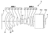
図4に、本発明の異なる投写用レンズシステム5のレンズ配置を示してある。本例の投写用レンズシステム5も、絞りSTの前後で2群に分けることが可能な11枚のレンズを備えており、スクリーン9の側から前群G1はレンズL11〜L16の6枚で構成され、後群G2はレンズL21〜L25の5枚により構成されている。これらのレンズL11〜L16およびL21〜L25の基本的な形状は第1の実施例と同様であり、本例の投写用レンズシステム5も、スクリーン側より、負−負−負−正−負−正−正―負−正−正−正の11枚構成のレンズシステムである。それらのレンズの詳細なデータを以下に示してある。
(Second embodiment)
FIG. 4 shows the lens arrangement of a different
レンズデータ(No.2)
No R D nd vd
1 81.466 4.00 1.49180 57.2 レンズL11
2 37.008 6.82
3 35.560 2.80 1.58913 61.3 レンズL12
4 16.235 9.53
5 456.823 2.40 1.58913 61.3 レンズL13
6 20.240 8.35
7 26.554 4.92 1.80610 33.3 レンズL14
8 -180.497 6.11
9 60.757 1.80 1.58913 61.3 レンズL15
10 12.249 2.37
11 16.128 3.65 1.69895 30.1 レンズL16
12 48.223 1.72
13 inf 2.78 絞りST
14 -341.014 7.07 1.49700 81.6 レンズL21
15 -18.761 1.89
16 -19.520 1.90 1.84666 23.8 レンズL22
17 25.684 7.67 1.49700 81.6 レンズL23
18 -21.689 0.25
19 60.515 6.22 1.49700 81.6 レンズL24
20 -35.791 0.20
21 59.234 4.48 1.80518 25.5 レンズL25
22 -101.758 3.50
23 inf 26.00 1.51680 64.2 フィルタFG1
24 inf 1.00
25 inf 3.00 1.48749 70.4 フィルタFG2
26 inf 2.65
Lens data (No. 2)
No RD nd vd
1 81.466 4.00 1.49180 57.2 Lens L11
2 37.008 6.82
3 35.560 2.80 1.58913 61.3 Lens L12
4 16.235 9.53
5 456.823 2.40 1.58913 61.3 Lens L13
6 20.240 8.35
7 26.554 4.92 1.80610 33.3 Lens L14
8 -180.497 6.11
9 60.757 1.80 1.58913 61.3 Lens L15
10 12.249 2.37
11 16.128 3.65 1.69895 30.1 Lens L16
12 48.223 1.72
13 inf 2.78 Aperture ST
14 -341.014 7.07 1.49700 81.6 Lens L21
15 -18.761 1.89
16 -19.520 1.90 1.84666 23.8 Lens L22
17 25.684 7.67 1.49700 81.6 Lens L23
18 -21.689 0.25
19 60.515 6.22 1.49700 81.6 Lens L24
20 -35.791 0.20
21 59.234 4.48 1.80518 25.5 Lens L25
22 -101.758 3.50
23 inf 26.00 1.51680 64.2 Filter FG1
24 inf 1.00
25 inf 3.00 1.48749 70.4 Filter FG2
26 inf 2.65
第1のメニスカスレンズL11はプラスチック製であり、その両面の第1面(S1)および第2面(S2)は非球面となっている。それらの面の非球面係数は以下の通りである。 The first meniscus lens L11 is made of plastic, and the first surface (S1) and the second surface (S2) of both surfaces thereof are aspherical surfaces. The aspheric coefficients of these surfaces are as follows.
第1面(S1)
R=81.466、 K=0.0000
A=2.35775×10⁻⁵ 、 B=−3.85714×10⁻⁸
C=5.14722×10⁻¹¹、 D=−2.14256×10⁻¹⁴
第2面(S2)
R=37.008、 K=0.0000
A=1.87132×10⁻⁵ 、 B=−6.03735×10⁻⁸
C=1.18156×10⁻¹⁰、 D=−9.00210×10⁻¹⁴
本例のレンズシステム5の各パラメータは次の通りである。
全体の合成焦点f(mm): 11.65
全長(mm): 86.92
First side (S1)
R = 81.466, K = 0.0000
A = 2.35775 × 10 −5 , B = −3.885714 × 10 −8
C = 5.147422 × 10 −11 , D = −2.14256 × 10 −14
Second side (S2)
R = 37.008, K = 0.0000
A = 1.87132 × 10 −5 , B = −6.03735 × 10 −8
C = 1.18156 × 10 −10 , D = −9.0100 × 10 −14
Each parameter of the
Overall synthetic focus f (mm): 11.65
Full length (mm): 86.92
このレンズシステム5も、スクリーン側から前群G1の屈折力が負、後群G2の屈折力が正のパワーのレンズ群が配置されたレトロフォーカス型のレンズシステムであり、ライトバルブ4の側がテレセントリックとなり、ライトバルブ4が液晶あるいはDMDのプロジェクタ装置に適したレンズシステムである。また、最もスクリーン側に配置されたスクリーン側に凸で負のパワーの第1のメニスカスレンズL11は、プラスチック製であり、その両面S1およびS2が非球面となっている。さらに、第1のレンズL11の両曲面S1およびS2の近軸曲率半径は、第2のメニスカスレンズL12のスクリーン側の面S3の曲率半径よりも大きく、第2のレンズL12より低い屈折率となるように設計されている。したがって、このレンズシステム5も、大口径の非球面レンズを採用することにより収差補正能力を高くでき、その一方で非球面レンズの熱変形の影響を限られたものにすることができるシステムとなっている。
This
図5に、この投写用レンズシステム5の球面収差、非点収差および歪曲収差を示してある。これらの図に示してあるように、本例のレンズシステム5の縦収差も、ほぼ±0.1mm程度の範囲に収まり、また、歪曲収差は1%以下の範囲に収まっている。本例のレンズシステム5の諸収差の値も、特許文献1として示した特開2002−357769号公報に開示された、同じ11枚構成の投写用レンズシステムの諸収差の値より数段優れたレベルである。したがって、本発明の投写用レンズシステム5においては、最もスクリーン側のメニスカスレンズL11を非球面にすることにより、2枚の非球面レンズを採用したレンズシステムより数段高い結像性能のレンズシステムが得られていることが分かる。
FIG. 5 shows the spherical aberration, astigmatism, and distortion of the
このように、本発明に係るレンズシステムは、最もスクリーン側に負のメニスカスレンズが配置されており、コンパクトで大きな画角が得られると共に、一枚の径の大きな非球面のレンズを採用することにより、従来の非球面レンズを2枚採用したシステムよりも低コストのレンズシステムでありながら数段高い収差補正性能を得ることが可能となっている。したがって、様々なタイプのプロジェクタに採用することにより、いっそう鮮明な画像を投写することができる。特に、非球面レンズの屈折力を相対的に弱く設定することにより熱変形による収差補正性能の低下も防止できる構成となっているので、熱の影響が大きいリアプロジェクタ型の投写装置においても、本発明の投写用レンズシステムを用いることにより、いっそう鮮明で安定した画像を得ることができる。また、上記では、2群のレンズシステムに基づき、本発明を説明しているが、1群あるいは3群以上のレンズシステムについても本発明を適用することができる。また、レンズがフォーカシング以外では移動しない単焦点型のレンズシステムに基づき本発明を説明しているが、ズーミングのためにレンズあるいはレンズ群が移動するズームレンズシステムにおいても本発明を適用することが可能である。 Thus, in the lens system according to the present invention, the negative meniscus lens is arranged on the most screen side, and a compact and large angle of view is obtained, and an aspherical lens having a large diameter is adopted. As a result, it is possible to obtain aberration correction performance that is several steps higher, although the lens system is lower in cost than a system that employs two conventional aspheric lenses. Therefore, by adopting it in various types of projectors, it is possible to project a clearer image. In particular, by setting the refractive power of the aspherical lens to be relatively weak, it is possible to prevent a decrease in aberration correction performance due to thermal deformation. By using the projection lens system of the invention, a clearer and more stable image can be obtained. In the above description, the present invention is described based on a two-group lens system. However, the present invention can be applied to a lens system including one group or three or more groups. Although the present invention has been described based on a single-focus lens system in which the lens does not move except for focusing, the present invention can also be applied to a zoom lens system in which a lens or a lens group moves for zooming. It is.
1 リアプロジェクタ
2 ハウジング
3 光源
4 ライトバルブ(光変調器)
5 投写用レンズシステム
9 スクリーン
1
5
Claims (4)
Priority Applications (2)
| Application Number | Priority Date | Filing Date | Title |
|---|---|---|---|
| JP2004097850A JP2005283966A (en) | 2004-03-30 | 2004-03-30 | Lens system for projection and projector device |
| US11/087,477 US7119966B2 (en) | 2004-03-30 | 2005-03-23 | Projection lens system and projector |
Applications Claiming Priority (1)
| Application Number | Priority Date | Filing Date | Title |
|---|---|---|---|
| JP2004097850A JP2005283966A (en) | 2004-03-30 | 2004-03-30 | Lens system for projection and projector device |
Publications (2)
| Publication Number | Publication Date |
|---|---|
| JP2005283966A true JP2005283966A (en) | 2005-10-13 |
| JP2005283966A5 JP2005283966A5 (en) | 2007-03-29 |
Family
ID=35053986
Family Applications (1)
| Application Number | Title | Priority Date | Filing Date |
|---|---|---|---|
| JP2004097850A Pending JP2005283966A (en) | 2004-03-30 | 2004-03-30 | Lens system for projection and projector device |
Country Status (2)
| Country | Link |
|---|---|
| US (1) | US7119966B2 (en) |
| JP (1) | JP2005283966A (en) |
Families Citing this family (3)
| Publication number | Priority date | Publication date | Assignee | Title |
|---|---|---|---|---|
| TWI233983B (en) * | 2004-01-20 | 2005-06-11 | Asia Optical Co Inc | Level device |
| US7460307B2 (en) * | 2004-05-17 | 2008-12-02 | Panasonic Corporation | Projector lens system |
| TW201037352A (en) * | 2009-04-10 | 2010-10-16 | Young Optics Inc | Fixed-focus lens |
Citations (7)
| Publication number | Priority date | Publication date | Assignee | Title |
|---|---|---|---|---|
| JPH0469611A (en) * | 1990-07-10 | 1992-03-04 | Minolta Camera Co Ltd | Fisheye lens system |
| JPH0996759A (en) * | 1995-09-28 | 1997-04-08 | Fuji Photo Optical Co Ltd | Retro-focus type lens |
| JPH1172700A (en) * | 1997-08-29 | 1999-03-16 | Canon Inc | Projection optical system and projector using it |
| JPH11305116A (en) * | 1998-04-24 | 1999-11-05 | Sony Corp | Projection lens |
| JP2002031754A (en) * | 2000-07-14 | 2002-01-31 | Hitachi Ltd | Lens device for projection and projection type picture display device |
| WO2002071124A1 (en) * | 2001-01-17 | 2002-09-12 | 3M Innovative Properties Company | Compact, telecentric projection lenses for use with pixelized panels |
| JP2003233000A (en) * | 2002-02-07 | 2003-08-22 | Sharp Corp | Projection optical system |
Family Cites Families (6)
| Publication number | Priority date | Publication date | Assignee | Title |
|---|---|---|---|---|
| JP2548359B2 (en) | 1989-03-01 | 1996-10-30 | 松下電器産業株式会社 | Projection lens and projection TV using it |
| US6084719A (en) * | 1997-08-29 | 2000-07-04 | Canon Kabushiki Kaisha | Projection lens |
| JPH11194266A (en) * | 1997-10-29 | 1999-07-21 | Fuji Photo Optical Co Ltd | Wide angle lens |
| JP2002357769A (en) | 2001-05-31 | 2002-12-13 | Chinontec Kk | Projection lens device and projector device |
| JP2002365534A (en) | 2001-06-05 | 2002-12-18 | Chinontec Kk | Projection lens device and projector device |
| JP2002365537A (en) | 2001-06-05 | 2002-12-18 | Chinontec Kk | Projection lens device and projector device |
-
2004
- 2004-03-30 JP JP2004097850A patent/JP2005283966A/en active Pending
-
2005
- 2005-03-23 US US11/087,477 patent/US7119966B2/en not_active Expired - Fee Related
Patent Citations (7)
| Publication number | Priority date | Publication date | Assignee | Title |
|---|---|---|---|---|
| JPH0469611A (en) * | 1990-07-10 | 1992-03-04 | Minolta Camera Co Ltd | Fisheye lens system |
| JPH0996759A (en) * | 1995-09-28 | 1997-04-08 | Fuji Photo Optical Co Ltd | Retro-focus type lens |
| JPH1172700A (en) * | 1997-08-29 | 1999-03-16 | Canon Inc | Projection optical system and projector using it |
| JPH11305116A (en) * | 1998-04-24 | 1999-11-05 | Sony Corp | Projection lens |
| JP2002031754A (en) * | 2000-07-14 | 2002-01-31 | Hitachi Ltd | Lens device for projection and projection type picture display device |
| WO2002071124A1 (en) * | 2001-01-17 | 2002-09-12 | 3M Innovative Properties Company | Compact, telecentric projection lenses for use with pixelized panels |
| JP2003233000A (en) * | 2002-02-07 | 2003-08-22 | Sharp Corp | Projection optical system |
Also Published As
| Publication number | Publication date |
|---|---|
| US7119966B2 (en) | 2006-10-10 |
| US20050219706A1 (en) | 2005-10-06 |
Similar Documents
| Publication | Publication Date | Title |
|---|---|---|
| US8345357B2 (en) | Optical system, image projection apparatus including the same and an image pickup device | |
| JP4864600B2 (en) | Projection type zoom lens and projection type display device | |
| US7715111B2 (en) | Projection zoom lens system and projection type display apparatus | |
| JP4349550B2 (en) | Reflective projection optics | |
| JP4855024B2 (en) | Two-group zoom projection lens and projection display device | |
| US8116010B2 (en) | Projection variable focus lens and projection display device | |
| US8223435B2 (en) | Zoom lens for projection and projection-type display device | |
| JP7135298B2 (en) | Projection optical system, image projection device | |
| US7489449B2 (en) | Zoom lens for projection and projection display device | |
| KR20050052397A (en) | Projection lens | |
| JP5560636B2 (en) | Zoom lens and projection display device using the same | |
| CN201725080U (en) | Varifocus lens for projection and projection-type displaying device | |
| JP2008176261A (en) | Zoom lens for projection and projection type display device | |
| CN100376914C (en) | Zooming-projection camera lens | |
| JP2005300619A (en) | Zoom lens and image projection device having same | |
| JP2012088518A (en) | Optical correction type zoom lens and projection type display device using the same | |
| JP2006145671A (en) | Zoom lens for projection and projector device | |
| JP2007219361A (en) | Zoom lens and projector device | |
| JP4851146B2 (en) | Two-group zoom projection lens and projection display device | |
| US7119966B2 (en) | Projection lens system and projector | |
| JP4177633B2 (en) | Wide-angle lens and video enlargement projection system, video projector, rear projector, and multivision system using the same | |
| JP4340432B2 (en) | Projection zoom lens | |
| JP6167652B2 (en) | Projection zoom lens and image display device | |
| JP2000206409A (en) | Zoom lens and projection device having the same | |
| JPH1172700A (en) | Projection optical system and projector using it |
Legal Events
| Date | Code | Title | Description |
|---|---|---|---|
| A521 | Request for written amendment filed |
Free format text: JAPANESE INTERMEDIATE CODE: A523 Effective date: 20070207 |
|
| A621 | Written request for application examination |
Free format text: JAPANESE INTERMEDIATE CODE: A621 Effective date: 20070207 |
|
| A977 | Report on retrieval |
Free format text: JAPANESE INTERMEDIATE CODE: A971007 Effective date: 20100223 |
|
| A131 | Notification of reasons for refusal |
Free format text: JAPANESE INTERMEDIATE CODE: A131 Effective date: 20100226 |
|
| A02 | Decision of refusal |
Free format text: JAPANESE INTERMEDIATE CODE: A02 Effective date: 20100629 |