JP2005283703A - Sound absorbing material - Google Patents
Sound absorbing material Download PDFInfo
- Publication number
- JP2005283703A JP2005283703A JP2004094120A JP2004094120A JP2005283703A JP 2005283703 A JP2005283703 A JP 2005283703A JP 2004094120 A JP2004094120 A JP 2004094120A JP 2004094120 A JP2004094120 A JP 2004094120A JP 2005283703 A JP2005283703 A JP 2005283703A
- Authority
- JP
- Japan
- Prior art keywords
- sound absorbing
- absorbing material
- thickness
- film
- sound
- Prior art date
- Legal status (The legal status is an assumption and is not a legal conclusion. Google has not performed a legal analysis and makes no representation as to the accuracy of the status listed.)
- Pending
Links
Images

Abstract
Description
本発明は、吸音材に関する。 The present invention relates to a sound absorbing material.
例えば、自動車内には、フェルトや発泡体、ガラスウール等からなる吸音材が多用されている。また、自動車用の吸音材は燃費の改善等のため、軽量な吸音材が求められている。さらに、ディーゼルエンジン車においては、1〜3KHz付近の吸音性向上が求められている。 For example, sound absorbing materials made of felt, foam, glass wool or the like are frequently used in automobiles. In addition, a sound absorbing material for automobiles is required to be lightweight for improving fuel consumption. Furthermore, in a diesel engine vehicle, an improvement in sound absorption near 1 to 3 KHz is required.
従来のフェルトやガラスウールなどの繊維体からなる吸音材は、一般的に300g/m2〜1600g/m2の重量範囲で用いられている。また、表面を凹凸に賦形したグラスウール、ロックウール、多孔質ボード等に樹脂フィルムを張り、外枠材に収納することが提案されているが、その場合、繊維体に凹凸を形成するためのバインダーや成形型が必要となり、コストや手間がかかる。さらに吸音材が圧縮された場合には、凸部が潰れて圧縮解除後も復元しなくなり、繊維体の表面と樹脂フィルムが略全体で接触して樹脂フィルムの振動が制限され、良好な吸音性が得られなくなる。 Sound absorbing material made of a fiber material such as a conventional felt or glass wool is generally used in a weight range of 300g / m 2 ~1600g / m 2 . In addition, it has been proposed that a resin film is stretched on glass wool, rock wool, porous board, etc. whose surface is uneven, and stored in the outer frame material. A binder and a mold are required, and cost and labor are required. In addition, when the sound absorbing material is compressed, the projections are crushed and cannot be restored even after being released from compression, and the surface of the fiber body and the resin film come into contact with each other almost entirely, limiting the vibration of the resin film, and good sound absorption Cannot be obtained.
また、多孔質材料からなる吸音材において、1〜3KHz付近の吸音性を改善する方法として、厚みを増大させることや、全面にフィルムを張ることが行われている。しかし、厚みを増大させると吸音材の重量が増大する問題や、設置空間が制限される設置場所に吸音材を設置できなくなる問題が発生する。それに対して全面にフィルムを張る場合には、フィルムの膜振動によって1〜3KHz付近の吸音性を向上させることが可能なものの、全体的な吸音性については低下する傾向にある。 Further, in a sound absorbing material made of a porous material, increasing the thickness or stretching a film over the entire surface is performed as a method for improving the sound absorbing property in the vicinity of 1 to 3 kHz. However, when the thickness is increased, there arises a problem that the weight of the sound absorbing material increases and a problem that the sound absorbing material cannot be installed in an installation place where the installation space is limited. On the other hand, when the film is stretched over the entire surface, although the sound absorbing property in the vicinity of 1 to 3 kHz can be improved by the film vibration of the film, the overall sound absorbing property tends to be lowered.
さらに、空気が封入された多数の凸部を表面に有する樹脂フィルムを、多孔質材料の表面に貼り合わせたものも提案されているが、表面側に凹凸が現れるため、使用時に表面にごみが溜まりやすい問題や、施工時に空気封入凸部が破損し易い問題がある。
本発明は前記の点に鑑みなされたもので、厚みを増大させることなく、1〜3KHz付近の吸音性を向上させることができ、しかも軽量で安価な吸音材の提供を目的とする。 The present invention has been made in view of the above points, and it is an object of the present invention to provide a light-absorbing material that can improve the sound-absorbing property in the vicinity of 1 to 3 kHz without increasing the thickness, and is lightweight.
請求項1の発明は、平板の多孔質弾性発泡体の表面に複数の凹凸が形成された基材と、前記凸部の頂部間に張設されて前記凸部の頂部と接合した被膜とよりなる吸音材に係る。
The invention of
請求項2の発明は、請求項1において、前記多孔質弾性発泡体の凹凸が、プロファイル加工により形成されたことを特徴とする。 According to a second aspect of the present invention, in the first aspect, the irregularities of the porous elastic foam are formed by profile processing.
請求項3の発明は、請求項1又は2において、前記被膜が厚み10〜1000μmのプラスチックフィルムであることを特徴とする。 A third aspect of the invention is characterized in that, in the first or second aspect, the coating film is a plastic film having a thickness of 10 to 1000 μm.
請求項4の発明は、請求項1から3の何れか一項において、前記凸部の間隔が5〜200mmであることを特徴とする。 According to a fourth aspect of the present invention, in any one of the first to third aspects, the interval between the convex portions is 5 to 200 mm.
請求項5の発明は、請求項1から4の何れか一項において、前記基材における凸部と凹部の高低差が3〜70mmであることを特徴とする。 A fifth aspect of the present invention is characterized in that, in any one of the first to fourth aspects, the height difference between the convex portion and the concave portion in the substrate is 3 to 70 mm.
請求項6の発明は、請求項1から5の何れか一項において、前記基材における凹部位置の厚みH2が1〜20mmであることを特徴とする。 A sixth aspect of the present invention is characterized in that, in any one of the first to fifth aspects, the thickness H2 of the concave portion position in the substrate is 1 to 20 mm.
本発明によれば、吸音材は、平板の多孔質弾性発泡体の表面に複数の凹凸部が形成された基材と、前記凸部の頂部間に張設されて前記凸部の頂部と接合した被膜とよりなるため、被膜の膜振動による吸音性向上作用、特には1〜3KHz付近の吸音性を向上することができ、吸音材の厚みを増大することなく吸音性を向上させることができる。しかも、前記被膜が基材の凸部の頂部と接合されているため、被膜の膜振動を凸部間で確実に行わせることができ、吸音性の向上がより良好となる。 According to the present invention, the sound absorbing material is bonded between the base material having a plurality of uneven portions formed on the surface of the flat porous elastic foam and the top portion of the convex portion. Therefore, it is possible to improve the sound absorbing property by the film vibration of the coating, particularly the sound absorbing property in the vicinity of 1 to 3 kHz, and the sound absorbing property can be improved without increasing the thickness of the sound absorbing material. . And since the said film is joined with the top part of the convex part of a base material, the film vibration of a film can be reliably performed between convex parts, and the improvement of a sound absorption property becomes more favorable.
さらに、請求項2のプロファイル加工は、公知のごとく、平板状の多孔質弾性発泡体を、表面が凹凸の二本のロール間に通して圧縮すると共に、その圧縮状態の多孔質弾性発泡体の中央部を刃物で切断することにより、切断後の多孔質弾性発泡体が復元した際に前記切断面に複数の凹凸を有するものとなる加工方法であり、型を用いなくても複数の凹凸を基材の表面に形成できるため、安価な吸音材を得ることができる。また、前記基材が多孔質弾性発泡体からなるため、吸音材の設置場所によっては、設置作業時に吸音材を一旦圧縮しなければならないことがあっても、前記圧縮によって潰れた凸部が、圧縮解除後には復元するので、凸部の頂部に接合されている被膜の膜振動による吸音効果を圧縮解除後も得ることができる。 Furthermore, as is well known, the profile processing according to claim 2 compresses a porous elastic foam having a flat plate shape by passing it between two rolls having an uneven surface, and the compressed porous elastic foam in the compressed state. It is a processing method that has a plurality of irregularities on the cut surface when the porous elastic foam after cutting is restored by cutting the central portion with a blade, and the plurality of irregularities can be formed without using a mold. Since it can form on the surface of a base material, an inexpensive sound-absorbing material can be obtained. In addition, since the base material is made of a porous elastic foam, depending on the installation location of the sound absorbing material, even if it may be necessary to compress the sound absorbing material once during the installation work, the convex portion collapsed by the compression, Since the restoration is performed after the compression is released, the sound absorption effect by the film vibration of the coating bonded to the top of the convex portion can be obtained even after the compression is released.
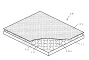
図1は本発明の一実施例における吸音材の一部切り欠き斜視図、図2は同実施例における基材の斜視図である。 FIG. 1 is a partially cutaway perspective view of a sound absorbing material in one embodiment of the present invention, and FIG. 2 is a perspective view of a base material in the same embodiment.
図1に示す吸音材10は、基材11と被膜21とよりなる。前記基材11は、図2からよりよく理解されるように、平板の多孔質弾性発泡体の表面にプロファイル加工による複数の凹凸が形成されたものである。前記多孔質弾性発泡体としては、プロファイル加工が可能なものであれば特に限定されない。使用可能な多孔質弾性発泡体として、軟質ポリウレタンフォーム、メラミンフォーム、ゴムスポンジ、オレフィンフォームなどを挙げることができる。また、前記多孔質弾性発泡体は、密度が15〜40kg/m3、通気量が10〜50cc/cm3/sec(JIS L 1096)のものが、軽量性及び吸音性を良好とする上で好ましい。ただし、発泡体単体でみると、前記範囲外であっても本発明の構造とすることで、従来の吸音材よりも良好な吸音性を示す。
A
前記凹凸は公知のプロファイル加工によって形成されたものであり、図示の例では、前記多孔質弾性発泡体の片面に複数の凹部13と凸部15からなる凹凸が形成されているが、多孔質弾性発泡体の両面に前記凹凸を形成してもよい。
The unevenness is formed by a known profile processing. In the example shown in the figure, the unevenness composed of a plurality of concave portions 13 and
前記凸部15の間隔(頂部間隔)は、5mm〜200mmが好ましい。5mm未満の場合には、前記凸部15間で前記被膜21の自由度が低下し、被膜21の膜振動による効果的な吸音性向上を図れなくなる。また200mmを超えると、前記被膜21に撓みが発生した際に、前記被膜21が前記凹部13と接触して被膜21の膜振が効果的に行われなくなる。前記理由により、前記凸部15の間隔は5mm〜200mmが好ましく、さらには30mm〜50mmがより好ましい。
As for the space | interval (top part space | interval) of the said convex
前記凸部15と前記凹部13の高低差、すなわち前記凸部15の位置における基材11の厚みH1と前記凹部13の位置における基材11の厚みH2の高低差、H1−H2の値は、3mm〜70mmが好ましい。3mm未満の場合には前記凹部13と前記被膜21の間の隙間が実質的になくなって被膜の自由度が損なわれ、良好な吸音性が得られなくなる。それに対して70mmを超えると、前記吸音材10の厚み増大によって、前記吸音材10の軽量性が損なわれるのみならず、吸音材の設置場所に制限を受けるようになる。なお、前記基材11における凹部13位置の厚みH2:凸部位置の厚みH1は、1:1.5〜1:4であるのが好ましい。凹部13の位置の厚みH2に対する凸部15の位置の厚みH1の比が1.5より小の場合には、前記被膜21の良好な膜振動が得難くなり、それに対して1.5より大の場合には軽量性が難しくなる。さらに、前記基材11における凹部13の位置の厚みH2は、1〜20mmが好ましい。1mmよりも薄いと良好な吸音性が得られなくなり、成形後、凹部の谷の底で貫通孔が形成される不具合を生じやすい。それに対して20mmより厚いと前記吸音材10の軽量性が損なわれるのみならず、吸音材の設置場所に制限を受けるようになる。
The height difference between the
前記被膜21は、プラスチックフィルムで構成される。プラスチックフィルムの材質は限定されず、例えば、ポリエチレン、ポリウレタン、ポリエチレンテレフタレート、ポリアミド系、シリコン系等を挙げることができる。また、前記被膜21は、厚みが10〜1000μmのものが、膜振動性に優れ、良好な吸音性が得られるために好ましい。 The coating 21 is made of a plastic film. The material of the plastic film is not limited, and examples thereof include polyethylene, polyurethane, polyethylene terephthalate, polyamide, and silicon. Further, the coating film 21 having a thickness of 10 to 1000 μm is preferable because it has excellent film vibration characteristics and good sound absorption.
前記被膜21は、前記凹部13との間に空間を残して前記凸部15間に張設され、前記基材11の凹凸側の表面を覆う。前記被膜21と前記凸部15とは、前記凸部15の頂部15aにおいて接合されている。前記接合は、接着剤によるものでも、あるいは前記凸部15の頂部15aを火炎によって溶融し、前記溶融状態の凸部15の頂部15aに前記被膜21を圧着する火炎溶着によるもの、あるいはその他の接合方法でもよい。また、前記被膜21は、前記基材11の凹凸表面を覆っていれば、用途により基材11の全面が被膜21で覆われていてもよく、その場合でも良好な吸音性が得られる。さらに、その場合には、前記基材11が被膜であるプラスチックフィルムにより覆われることにより、基材である多孔質弾性発泡体の耐久性を増大させることも期待できる。
The coating 21 is stretched between the
以下、具体的な実施例を示す。実施例1の吸音材は、基材として軟質ポリウレタンフォーム(密度18kg/m3、通気量30cc/cm3/sec(JIS L 1096)、品番F−21、株式会社イノアックコーポレーション製)をプロファイル加工して片面に凹凸を形成したものを用いた。また、実施例1における基材は、凸部の間隔(頂部間隔)が30mm、凸部の位置における基材の厚みH1が10mm、凹部の位置における基材の厚みH2が3mm、凸部と凹部の高低差、H1−H2の値が7mm、H2:H1が1:3.3であり、基材の全体寸法は、10×300×300mmである。また、実施例1における被膜は、厚み20μmのポリウレタンフィルムを使用し、火炎溶着によって基材の凸部の頂部に接合することにより、凸部間に張設した。
Specific examples will be described below. The sound-absorbing material of Example 1 was profile processed with a flexible polyurethane foam (density 18 kg / m 3 ,
実施例2の吸音材は、実施例1と同じ軟質ポリウレタンフォームを基材に用い、凸部の間隔(頂部間隔)を30mm、凸部の位置における基材の厚みH1を10mm、凹部の位置における基材の厚みH2を5mm、凸部と凹部の高低差、H1−H2の値を5mm、H2:H1を1:2とした点を除き、他は実施例1の吸音材と同様とした。 The sound-absorbing material of Example 2 uses the same flexible polyurethane foam as that of Example 1 as a base material, the interval between the convex portions (top interval) is 30 mm, the thickness H1 of the base material at the convex portion position is 10 mm, and the concave portion position. Except for the point that the thickness H2 of the base material was 5 mm, the height difference between the convex part and the concave part, the value of H1-H2 was 5 mm, and H2: H1 was 1: 2, the same as the sound absorbing material of Example 1.
参考のため、以下に示す比較例1〜4の吸音材を製造した。比較例1の吸音材は、10×300×300mmの繊維体(3M社製、シンサレート、TAI−2047)のみで構成した。比較例2の吸音材は、実施例1で用いた軟質ポリウレタンフォームを10×300×300mmとしたフォーム単体で構成した。比較例3の吸音材は、実施例1において被膜を設けない構成とし、その他は実施例1と同様の構成とした。比較例4の吸音材は、比較例2の軟質ポリウレタンフォームの両面に厚み20μmのポリウレタンフィルムを火炎溶着により貼着したもので構成した。表1に、実施例1〜2及び比較例1〜4の吸音材について、構成、凸部間隔、H1及びH2の値、H1−H2の値、重量、厚みを示す。 For reference, the sound absorbing materials of Comparative Examples 1 to 4 shown below were manufactured. The sound-absorbing material of Comparative Example 1 was composed only of a 10 × 300 × 300 mm fiber body (manufactured by 3M, Thinsulate, TAI-2047). The sound-absorbing material of Comparative Example 2 was composed of a single foam having the flexible polyurethane foam used in Example 1 as 10 × 300 × 300 mm. The sound-absorbing material of Comparative Example 3 has the same configuration as that of Example 1 except that the coating film is not provided in Example 1. The sound absorbing material of Comparative Example 4 was composed of a polyurethane film having a thickness of 20 μm adhered to both surfaces of the flexible polyurethane foam of Comparative Example 2 by flame welding. Table 1 shows the configuration, the spacing between the convex portions, the values of H1 and H2, the values of H1-H2, the weight, and the thickness of the sound absorbing materials of Examples 1-2 and Comparative Examples 1-4.

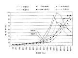
また、前記実施例1〜2と比較例1〜4について、JIS A 1405にしたがい垂直入射吸音率(%)を測定した。測定結果は図3に示すとおりである。図3から明らかなように、実施例1〜2の吸音材は、比較例1〜4の吸音材と比較すると被膜の自由度が高く、膜振動が行われることにより、1〜3KHzの吸音性が向上している。また実施例2の吸音材は、実施例1の吸音材よりも凹部の厚み(H2)が大であり、1〜3KHzにおける吸音率のピークが幾分低周波側へずれているが、1000〜3150Hzの吸音性については、実施例1の吸音材と同様に比較例1〜4の吸音材よりも優れている。 Moreover, about the said Examples 1-2 and Comparative Examples 1-4, the normal incidence sound absorption coefficient (%) was measured according to JISA1405. The measurement results are as shown in FIG. As is clear from FIG. 3, the sound absorbing materials of Examples 1 and 2 have a higher degree of freedom of coating compared to the sound absorbing materials of Comparative Examples 1 to 4, and sound absorption of 1 to 3 KHz is achieved due to membrane vibration. Has improved. Further, the sound absorbing material of Example 2 has a larger thickness (H2) of the recess than the sound absorbing material of Example 1, and the peak of the sound absorption coefficient at 1 to 3 kHz is somewhat shifted to the low frequency side. Similar to the sound absorbing material of Example 1, the sound absorbing property of 3150 Hz is superior to that of Comparative Examples 1 to 4.
10 吸音材
11 基材
13 凹部
15 凸部
15a 凸部の頂部
21 被膜
H1 凸部位置における基材の厚み
H2 凹部位置における基材の厚み
DESCRIPTION OF
Claims (6)
The sound absorbing material according to any one of claims 1 to 5, wherein a thickness H2 of the concave portion position in the base material is 1 to 20 mm.
Priority Applications (1)
| Application Number | Priority Date | Filing Date | Title |
|---|---|---|---|
| JP2004094120A JP2005283703A (en) | 2004-03-29 | 2004-03-29 | Sound absorbing material |
Applications Claiming Priority (1)
| Application Number | Priority Date | Filing Date | Title |
|---|---|---|---|
| JP2004094120A JP2005283703A (en) | 2004-03-29 | 2004-03-29 | Sound absorbing material |
Publications (1)
| Publication Number | Publication Date |
|---|---|
| JP2005283703A true JP2005283703A (en) | 2005-10-13 |
Family
ID=35182180
Family Applications (1)
| Application Number | Title | Priority Date | Filing Date |
|---|---|---|---|
| JP2004094120A Pending JP2005283703A (en) | 2004-03-29 | 2004-03-29 | Sound absorbing material |
Country Status (1)
| Country | Link |
|---|---|
| JP (1) | JP2005283703A (en) |
Cited By (9)
| Publication number | Priority date | Publication date | Assignee | Title |
|---|---|---|---|---|
| JP2007255189A (en) * | 2006-03-20 | 2007-10-04 | Pacific Ind Co Ltd | Engine cover |
| US7431127B2 (en) * | 2004-09-21 | 2008-10-07 | Durr Systems, Inc. | Compact noise silencer for an air blower |
| JP2009093064A (en) * | 2007-10-11 | 2009-04-30 | Yamaha Corp | Sound absorbing structure and acoustic room |
| US8371419B2 (en) | 2008-04-22 | 2013-02-12 | 3M Innovative Properties Company | Hybrid sound absorbing sheet |
| US8469145B2 (en) | 2008-04-14 | 2013-06-25 | 3M Innovative Properties Company | Multilayer sound absorbing sheet |
| US8573358B2 (en) | 2008-05-22 | 2013-11-05 | 3M Innovative Properties Company | Multilayer sound absorbing structure comprising mesh layer |
| KR101331471B1 (en) | 2012-07-04 | 2013-11-26 | 주식회사 예경산업개발 | A noise spread prevention cover for construction equipment |
| JP2014224330A (en) * | 2013-05-17 | 2014-12-04 | 王子ホールディングス株式会社 | Molding processing sheet and method for producing molding processing sheet |
| CN108231053A (en) * | 2018-03-13 | 2018-06-29 | 吉林大学 | A kind of acoustics packaging material with convex closure form and preparation method thereof |
Citations (3)
| Publication number | Priority date | Publication date | Assignee | Title |
|---|---|---|---|---|
| JPH0444279B2 (en) * | 1982-05-22 | 1992-07-21 | Metzeler Schaum Gmbh | |
| JP2001184076A (en) * | 1999-12-22 | 2001-07-06 | Nichias Corp | Sound absorbing structure |
| JP2003145487A (en) * | 2001-11-08 | 2003-05-20 | Inoac Corp | Uneven foam, and manufacturing method thereof |
-
2004
- 2004-03-29 JP JP2004094120A patent/JP2005283703A/en active Pending
Patent Citations (3)
| Publication number | Priority date | Publication date | Assignee | Title |
|---|---|---|---|---|
| JPH0444279B2 (en) * | 1982-05-22 | 1992-07-21 | Metzeler Schaum Gmbh | |
| JP2001184076A (en) * | 1999-12-22 | 2001-07-06 | Nichias Corp | Sound absorbing structure |
| JP2003145487A (en) * | 2001-11-08 | 2003-05-20 | Inoac Corp | Uneven foam, and manufacturing method thereof |
Cited By (10)
| Publication number | Priority date | Publication date | Assignee | Title |
|---|---|---|---|---|
| US7431127B2 (en) * | 2004-09-21 | 2008-10-07 | Durr Systems, Inc. | Compact noise silencer for an air blower |
| JP2007255189A (en) * | 2006-03-20 | 2007-10-04 | Pacific Ind Co Ltd | Engine cover |
| JP4607038B2 (en) * | 2006-03-20 | 2011-01-05 | 太平洋工業株式会社 | Engine cover |
| JP2009093064A (en) * | 2007-10-11 | 2009-04-30 | Yamaha Corp | Sound absorbing structure and acoustic room |
| US8469145B2 (en) | 2008-04-14 | 2013-06-25 | 3M Innovative Properties Company | Multilayer sound absorbing sheet |
| US8371419B2 (en) | 2008-04-22 | 2013-02-12 | 3M Innovative Properties Company | Hybrid sound absorbing sheet |
| US8573358B2 (en) | 2008-05-22 | 2013-11-05 | 3M Innovative Properties Company | Multilayer sound absorbing structure comprising mesh layer |
| KR101331471B1 (en) | 2012-07-04 | 2013-11-26 | 주식회사 예경산업개발 | A noise spread prevention cover for construction equipment |
| JP2014224330A (en) * | 2013-05-17 | 2014-12-04 | 王子ホールディングス株式会社 | Molding processing sheet and method for producing molding processing sheet |
| CN108231053A (en) * | 2018-03-13 | 2018-06-29 | 吉林大学 | A kind of acoustics packaging material with convex closure form and preparation method thereof |
Similar Documents
| Publication | Publication Date | Title |
|---|---|---|
| EP1742201A1 (en) | Porous sound absorbing structure | |
| US20040168853A1 (en) | Acoustic tile and its use in vehicle sound proofing | |
| JP4997057B2 (en) | Sound insulation for vehicles | |
| JP2014531356A (en) | Sound insulation assembly for automobile body | |
| WO2010092968A1 (en) | Automotive sound-absorbing sheet and automotive engine bottom cover including the sound-absorbing sheet | |
| KR20110031136A (en) | Sound absorbing cover, method of manufacturing thereof and method of sound absorbing | |
| JP2005283703A (en) | Sound absorbing material | |
| JP2009040071A (en) | Sound absorbing material, and sound absorbing structure equipped with sound absorbing material | |
| JP2010234991A (en) | Sound insulating material for vehicle | |
| US20050233106A1 (en) | Floor laying material, piece mat, and arranging structure thereof | |
| JP2009167702A (en) | Sound absorbing body and its manufacturing method | |
| JP2011156897A (en) | Soundproof cover and manufacturing method of the same | |
| JP2009298339A (en) | Road surface side sound absorption floor undercover for automobile | |
| JP3012967B2 (en) | Sound insulation damping member for L-type connecting pipe | |
| JP3421982B2 (en) | Soundproof floor material and soundproof floor structure | |
| JP2008203542A (en) | Sound absorbing body | |
| JP2004190723A (en) | Mounting method of soundproofing material, soundproofed pipe, and manufacturing method therefor | |
| JP2002220009A (en) | Insulator for automobile | |
| JPH10329596A (en) | Floor carpet for automobile | |
| JP2009167701A (en) | Sound absorbing structure | |
| KR101838718B1 (en) | Panel vibration type sound absorptive material | |
| JP5052453B2 (en) | Ventilation duct | |
| JP2001138908A (en) | Soundproofing damping material | |
| JP2005088706A (en) | Sound insulating material for vehicle | |
| JP2007001271A (en) | Lining material and ceiling material for vehicles |
Legal Events
| Date | Code | Title | Description |
|---|---|---|---|
| A621 | Written request for application examination |
Free format text: JAPANESE INTERMEDIATE CODE: A621 Effective date: 20061110 |
|
| A131 | Notification of reasons for refusal |
Free format text: JAPANESE INTERMEDIATE CODE: A131 Effective date: 20080820 |
|
| A02 | Decision of refusal |
Free format text: JAPANESE INTERMEDIATE CODE: A02 Effective date: 20081216 |