JP2005276139A - Information input device - Google Patents
Information input device Download PDFInfo
- Publication number
- JP2005276139A JP2005276139A JP2004111401A JP2004111401A JP2005276139A JP 2005276139 A JP2005276139 A JP 2005276139A JP 2004111401 A JP2004111401 A JP 2004111401A JP 2004111401 A JP2004111401 A JP 2004111401A JP 2005276139 A JP2005276139 A JP 2005276139A
- Authority
- JP
- Japan
- Prior art keywords
- position information
- shadow
- screen
- unit
- image
- Prior art date
- Legal status (The legal status is an assumption and is not a legal conclusion. Google has not performed a legal analysis and makes no representation as to the accuracy of the status listed.)
- Pending
Links
Images


Classifications
-
- G—PHYSICS
- G07—CHECKING-DEVICES
- G07F—COIN-FREED OR LIKE APPARATUS
- G07F17/00—Coin-freed apparatus for hiring articles; Coin-freed facilities or services
- G07F17/32—Coin-freed apparatus for hiring articles; Coin-freed facilities or services for games, toys, sports, or amusements
- G07F17/3202—Hardware aspects of a gaming system, e.g. components, construction, architecture thereof
- G07F17/3216—Construction aspects of a gaming system, e.g. housing, seats, ergonomic aspects
- G07F17/322—Casino tables, e.g. tables having integrated screens, chip detection means
-
- G—PHYSICS
- G06—COMPUTING; CALCULATING OR COUNTING
- G06F—ELECTRIC DIGITAL DATA PROCESSING
- G06F3/00—Input arrangements for transferring data to be processed into a form capable of being handled by the computer; Output arrangements for transferring data from processing unit to output unit, e.g. interface arrangements
- G06F3/01—Input arrangements or combined input and output arrangements for interaction between user and computer
- G06F3/03—Arrangements for converting the position or the displacement of a member into a coded form
- G06F3/041—Digitisers, e.g. for touch screens or touch pads, characterised by the transducing means
- G06F3/042—Digitisers, e.g. for touch screens or touch pads, characterised by the transducing means by opto-electronic means
- G06F3/0421—Digitisers, e.g. for touch screens or touch pads, characterised by the transducing means by opto-electronic means by interrupting or reflecting a light beam, e.g. optical touch-screen
-
- G—PHYSICS
- G07—CHECKING-DEVICES
- G07F—COIN-FREED OR LIKE APPARATUS
- G07F17/00—Coin-freed apparatus for hiring articles; Coin-freed facilities or services
- G07F17/32—Coin-freed apparatus for hiring articles; Coin-freed facilities or services for games, toys, sports, or amusements
-
- G—PHYSICS
- G07—CHECKING-DEVICES
- G07F—COIN-FREED OR LIKE APPARATUS
- G07F17/00—Coin-freed apparatus for hiring articles; Coin-freed facilities or services
- G07F17/32—Coin-freed apparatus for hiring articles; Coin-freed facilities or services for games, toys, sports, or amusements
- G07F17/3202—Hardware aspects of a gaming system, e.g. components, construction, architecture thereof
- G07F17/3204—Player-machine interfaces
- G07F17/3209—Input means, e.g. buttons, touch screen
Abstract
Description
本発明は、情報入力装置に関し、より詳しくは、例えばスクリーンや大型ディスプレイなどの画像表示装置に画像を表示させるとともに、ユーザが表示された画像のある位置を指示した場合、その位置を情報の入力として扱うことができる情報入力装置に関する。 The present invention relates to an information input device. More specifically, for example, when an image is displayed on an image display device such as a screen or a large display, and the user indicates a position of the displayed image, the position is input to the information. It is related with the information input device which can be handled as.
ゲームセンター、遊技場、カジノなどにおかれている従来のテーブルゲーム機(CRTモニタなどにゲームテーブル画像を表示させて、ゲームテーブルとして利用するゲーム機)では、画像表示装置を水平に寝かせて配置し、テーブルモニタとして用いている。 In conventional table game machines (game machines in which a game table image is displayed on a CRT monitor or the like and used as a game table) in game centers, amusement halls, casinos, etc., the image display device is laid horizontally. It is used as a table monitor.
このようなゲーム機においては、ゲームテーブルのどの位置に賭け位置を決定したかをゲーム機にプレイヤが指示するために、各プレイヤの手元に設置されている操作部を用いていた。 In such a game machine, an operation unit installed at each player's hand is used in order for the player to instruct the game machine to which position on the game table the betting position has been determined.
このため、プレイヤの操作は各自の手元の操作部に限定され、実際のルーレットやカードゲームのように、プレイヤがゲームテーブルに手を伸ばしてチップを所定の位置にかけるような動作は行われず、実際のゲームに比べた場合臨場感に欠けるという欠点があった。 For this reason, the player's operation is limited to the operation unit at hand, and the player does not perform an operation of reaching the game table and placing the chip at a predetermined position like an actual roulette or card game, When compared with the actual game, there was a drawback of lack of realism.
かかる欠点を解消する技術として、ゲームテーブルにタッチパネルセンサを設け、ゲームテーブルに触れることによりプレイヤの指示した位置を検出してゲームに反映させる方法が提案されている。
しかし、上記のようにタッチパネルセンサをゲームテーブルに設ける方法では、複数のプレイヤが同時にプレイできるゲーム機を実現する場合、ゲームテーブルも人数に合わせて大型化する必要があり、その結果大型のタッチパネルセンサが必要となるが、コストの高騰や水平に寝かせて設置した場合の強度の問題があり、また、タッチパネルセンサでは複数のプレイヤが同時にタッチした場合に位置検出できないという問題があった。 However, in the method of providing the touch panel sensor on the game table as described above, when realizing a game machine in which a plurality of players can play simultaneously, the game table needs to be increased in size according to the number of people, and as a result, the large touch panel sensor. However, there is a problem that the cost increases or the strength when the apparatus is placed horizontally laid down, and the touch panel sensor cannot detect the position when a plurality of players touch at the same time.
さらに、大勢のプレイヤが繰り返しタッチパネルセンサに触れるため、汚れによる検出制度の劣化、故障の問題があった。 Furthermore, since many players repeatedly touch the touch panel sensor, there is a problem of deterioration of the detection system due to dirt and failure.
本発明は、上記問題点を解決することを目的として、プレイヤの接触の検知によることなく、プレイヤの手などにより指示された位置を検出することが可能な情報入力装置を提供することにある。 In order to solve the above problems, an object of the present invention is to provide an information input device capable of detecting a position designated by a player's hand or the like without detecting the player's contact.
本発明は、上記問題点を解決するため手段として、以下のような特徴を有する。
本発明は、予め定められた一又は複数の入力領域を有するテーブル手段(結像手段、スクリーン)と、テーブル手段上の物体の位置を検出し、物体の位置情報を出力するための位置検出手段(位置検出部、センサ)と、前記位置検出手段からの物体の位置情報に基づいて、その物体の位置が所定時間前記入力領域の何れかにあるか否かを判定し、物体が所定時間その入力領域にあると判定した場合は、その位置情報を有効として扱う位置情報判定手段(位置情報判定部)とを有することを特徴としている。
The present invention has the following features as means for solving the above problems.
The present invention relates to table means (image forming means, screen) having one or more predetermined input areas, and position detection means for detecting the position of an object on the table means and outputting the position information of the object. (Position detection unit, sensor) and based on the position information of the object from the position detection means, it is determined whether the position of the object is in any of the input areas for a predetermined time, If it is determined that the current position is in the input area, it is characterized by having position information determination means (position information determination unit) that treats the position information as valid.
本発明によれば、所定時間の間物体が入力領域にとどまっているか否かを判定しながら、位置情報の出力を行うため、単にその入力領域上を通過して別の入力領域をプレイヤが指示するような場合にも、誤認識を発生させることなくプレイヤの意図する入力領域についての情報入力を行うことが可能となる。 According to the present invention, in order to output position information while determining whether or not an object has remained in the input area for a predetermined time, the player simply passes over the input area and instructs another input area. Even in such a case, it is possible to input information about the input area intended by the player without causing erroneous recognition.
また、発明の本態様では、位置検出手段からの物体の位置情報が前記物体が複数の入力領域に渡って位置することを示している場合、位置情報判定手段は、これら複数の入力領域のうちいずれか一の入力領域の位置情報を有効とし、他の入力領域の位置情報は無効として扱うようにしてもよい。 Further, in this aspect of the invention, when the position information of the object from the position detection means indicates that the object is located across a plurality of input areas, the position information determination means includes the plurality of input areas. The position information of any one input area may be validated and the position information of other input areas may be treated as invalid.
たとえばプレイヤが自己の入力領域として割り当てられた「BANKER」「引き分けs」「PLAYER」の3つのベット枠すべてにかかるように腕を伸ばして、自分から一番遠い位置にあるベット枠を手で指示した場合、手前にある他の2つのベット枠にも腕による影が落ち、情報入力装置が「BANKER」「引き分け」「PLAYER」のすべてが指示されたと誤認識する虞が生じるが、上記構成によれば、自分から一番遠い位置にあるベット枠が指示されたと情報入力装置にプレイヤの意図するところを正しく認識させることができ、誤認識を防止することが可能となる。 For example, the player extends his arm so that it covers all three bet frames “BANKER”, “Draw s” and “PLAYER” assigned as his input area, and manually points the bet frame farthest from him In this case, the other two bet frames in front of each other also cast shadows on their arms, and the information input device may misrecognize that all of “BANKER”, “Draw”, and “PLAYER” are instructed. According to this, when the bet frame that is farthest from the player is instructed, the information input device can be made to correctly recognize the place intended by the player, and erroneous recognition can be prevented.
本発明の別の態様は、画像を投影する投影手段(投影手段、DLP)と、前記投影手段により投影された画像を結像させるとともに、前記画像のある位置を指し示す指示部の影が投影されるスクリーン手段(結像手段、透過性スクリーン)と、前記スクリーン手段の背面を撮像し、前記指示部の影を含む画像データを出力する撮像手段(DVC)と、前記画像データに含まれる影に基づいて、前記指示部により指し示された位置を検出し、これを位置情報として出力する位置検出手段(位置検出部)と、前記位置検出手段からの位置情報に基づいて、その物体の位置が所定時間前記入力領域の何れかにあるか否かを判定し、物体が所定時間その入力領域にあると判定した場合は、その位置情報を有効として扱う位置情報判定手段(位置情報判定部)とを有し、前記位置検出手段は、前記影の濃淡に基づいて指示部の位置を判定することを特徴としている。 According to another aspect of the present invention, a projection unit (projection unit, DLP) that projects an image and an image projected by the projection unit are imaged, and a shadow of an instruction unit that indicates a position of the image is projected. Screen means (imaging means, transmissive screen), imaging means (DVC) for imaging the back surface of the screen means, and outputting image data including the shadow of the instruction unit, and shadows included in the image data Based on the position information from the position detecting means (position detecting section) for detecting the position indicated by the instruction section and outputting the position information as position information, the position of the object is determined based on the position information from the position detecting section. It is determined whether or not the object is in the input area for a predetermined time, and if it is determined that the object is in the input area for a predetermined time, position information determination means (position information determination) that treats the position information as valid. Parts) and have, the position detecting means is characterized in determining the position of the indicator based on the contrast of the shadow.
本発明の態様は、スクリーン手段を画像表示に用いるとともに、スクリーンに映る指示部の影を画像処理することにより、情報入力に用いる。本発明の態様は、影の位置を検出させるとともに、その影が所定時間どのような変化をするかをも検出して入力情報の一部として用いる。入力として用いられる影の変化は、影の移動、濃淡の変化などである。 According to the aspect of the present invention, the screen means is used for image display, and the shadow of the instruction unit reflected on the screen is image-processed for information input. According to the aspect of the present invention, the position of a shadow is detected, and how the shadow changes for a predetermined time is detected and used as a part of input information. The change of the shadow used as an input is a movement of the shadow, a change in shading or the like.
また、本発明の態様において、複数のプレイヤが同時に手でスクリーン手段を指し示す場合のように、複数の指示部の影が生じている場合に各影について位置が所定時間前記入力領域の何れかにあるか否かを判定し、物体が所定時間その入力領域にあると判定した場合は、その位置情報を有効として扱うようにしてもよい。その結果、一つのスクリーン手段を複数人の入力を受け付ける入力手段として利用することが可能となる。 In the aspect of the present invention, when the shadows of a plurality of instruction units are generated as in the case where a plurality of players simultaneously point to the screen means by hand, the position of each shadow is set to any one of the input areas for a predetermined time. If it is determined whether the object is in the input area for a predetermined time, the position information may be treated as valid. As a result, it is possible to use one screen means as an input means for receiving input from a plurality of persons.
この態様は、指示部とスクリーン手段との距離が近い部分程影が濃く、指示部とスクリーン手段との距離が遠い部分は影が薄くなるという特性を利用して、指示部の先端を特定して、指示部によってどの位置が指し示されているのかをより正確に特定することができる。 This mode uses the characteristic that the shadow is darker in the part where the distance between the pointing part and the screen means is closer, and the shadow is lighter in the part where the distance between the pointing part and the screen means is far away. Thus, it is possible to specify more accurately which position is indicated by the instruction unit.
本発明の別の態様において、位置情報判定手段は、影の濃淡の変化を所定時間測定し、測定結果に応じてプレイヤの入力回数の判定をさらに行うようにしてもよい。 In another aspect of the present invention, the position information determination unit may measure a change in shadow shading for a predetermined time and further determine the number of inputs by the player according to the measurement result.
指示部とスクリーン手段との距離が近い部分程影が濃く、指示部とスクリーン手段との距離が遠い部分は影が薄くなるという特性により、影の濃淡の変化を検出することにより、本発明の態様は、指示部によるスクリーン手段への押下動作のようなスクリーン手段に対して上下動の動きをも検出し、これを入力情報として処理させることが可能となる。 By detecting the change in the shade of the shadow by the characteristic that the shadow is darker in the part where the distance between the instruction part and the screen means is closer, and the shadow is thinner in the part where the distance between the instruction part and the screen means is far, According to the aspect, it is possible to detect a movement of the screen unit such as a pressing operation on the screen unit by the instruction unit, and to process this as input information.
また、本態様にかかる情報入力装置において、前記影は前記スクリーン手段上の位置に応じて定められた閾値に基づいて判定され、この閾値は前記投影手段からの距離又はスクリーン手段上の照度に応じて定められるようにしてもよい。 Further, in the information input device according to this aspect, the shadow is determined based on a threshold value determined according to the position on the screen unit, and the threshold value depends on a distance from the projection unit or an illuminance on the screen unit. May be determined.
スクリーン手段は投影手段から画像を映し出すために照射されており、投影手段の照射の中心は明るく、中心から離れるに従って暗くなる。従って、スクリーン手段上に形成される影もこの投影手段の照射の影響を受けて、投影手段の照射の中心では影の濃さは薄く、中心から離れるに従って影の濃さが濃くなる。スクリーン手段表面(前面、背面のいずれでも良い)のすべての位置について、影の有無の判定を行うための閾値を一定に定める構成とすると、投影手段の照射の中心に近づくほど影の存在が判定されづらく、一方中心から離れるに従って影の存在が判定されやすくなる虞がある。そこで、閾値は前記投影手段からの距離又はスクリーン手段上の照度に応じて定める様にして、この投影手段の照射の影響を考慮して影の存在判定を行うようにしている。 The screen means is irradiated to project an image from the projection means, and the center of irradiation of the projection means is bright and becomes darker as it goes away from the center. Therefore, the shadow formed on the screen means is also affected by the irradiation of the projection means, and the shadow density is thin at the center of irradiation of the projection means, and the shadow density increases as the distance from the center increases. If the threshold for determining whether or not there is a shadow is fixed for all positions on the surface of the screen means (either front or back), the presence of a shadow is determined as it approaches the irradiation center of the projection means. However, it is difficult to determine the presence of a shadow as the distance from the center increases. Therefore, the threshold value is determined according to the distance from the projection means or the illuminance on the screen means, and the presence of the shadow is determined in consideration of the influence of the irradiation of the projection means.
本発明によれば、有効な位置情報と判定された場合にゲームの処理が行われるため、指示部の移動を誤って入力としてマシンパワーを必要とする画像処理等を行うことを避けることができ、装置の処理能力を有効に活用できる。 According to the present invention, since the game process is performed when it is determined that the position information is valid, it is possible to avoid performing an image process or the like that requires machine power by erroneously inputting the movement of the instruction unit. The processing capacity of the device can be used effectively.
また、本発明の別の態様によれば、一つのスクリーン手段を複数人の入力を受け付ける入力手段として利用することが可能となる。 Further, according to another aspect of the present invention, it is possible to use one screen means as an input means for receiving input from a plurality of persons.
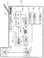
以下、図面を参照しながら本発明の実施の形態を説明する。図1は、本発明にかかる情報入力装置の基本的構成例を示す図である。 Embodiments of the present invention will be described below with reference to the drawings. FIG. 1 is a diagram showing a basic configuration example of an information input device according to the present invention.
[1.第1の実施の形態]
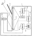
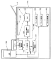
この情報入力装置1は、結像手段10と、画像データを供給するための映像制御手段30と、映像制御手段からの画像データに基づいて、この結像手段10前面に画像を投影するための投影手段20と、指示部Pの影PSが形成された結像手段10をその背面から撮影するための撮像手段50と、撮像手段50から出力される結像手段10背面の画像データを受け取り、この画像データから指示部Pの影PSの位置を判定し、位置情報を出力する位置検出手段60と、位置検出手段60からの位置情報に基づいて、所定時間影PSが予め定められた入力領域に位置するか否かを判定し、所定時間位置する場合には、この位置情報を有効なものとして出力する位置情報判定手段70と、位置情報判定手段70から出力される位置情報に基づいて結像手段10に映し出す画像を映像制御手段30に指令する全体制御手段80とを有している。
[1. First Embodiment]
This
結像手段10は透過性を有しており前面及び背面からの光を透過する。結像手段10は、たとえば液晶プロジェクター用の透過性スクリーンである。この結像手段10である透過性スクリーンは、光散乱層を有しており液晶プロジェクタなどからの光を効率よく散乱して、光コントラスト映像を映し出すスクリーンを含む。 The imaging means 10 is transmissive and transmits light from the front and back surfaces. The imaging means 10 is a transmissive screen for a liquid crystal projector, for example. The transmissive screen as the imaging means 10 includes a screen that has a light scattering layer and efficiently scatters light from a liquid crystal projector or the like to display a light contrast image.
ユーザUは結像手段10前面から結像手段10を見ると、結像手段10背面側から投影手段20によって射出された光学的画像が結像手段10上に結像して見え、その結果ユーザUは、投影手段20が照射した、画像データに対応する画像を看取することができるようになっている。
When the user U views the
指示部Pは、結像手段10前面に表示された画像の所望の箇所をユーザが指し示す物或いは手段であって、たとえばユーザU自身の手(腕部を含む)、指示棒などである。指示部Pは光源LSにより照らされており、結像手段10に指示部Pの影PSが映る。結像手段10は透過性を有するため、結像手段10背面から見た場合にも、この影PSが見えるようになっている。なお、光源LSは太陽のような自然光源であっても良いし、情報入力装置1が配置された環境(屋内)に設けられた照明装置であっても良いし、或いはまた、情報入力装置1に設けられた蛍光灯のような照明装置であっても良い。
The instruction unit P is an object or means for indicating the desired position of the image displayed on the front surface of the
投影手段20は画像データに基づいて光学的画像を結像手段10に投射可能な光学的投射系であって、たとえば液晶プロジェクタ(DLP(Digital Liquid Projector))などである。光源LSは、好ましくは白色光を発する光源である。白色光が結像手段10を透過することによって、結像手段10背面において指示部Pの影PSの領域が黒く見えるとともに、影PS以外の領域が白く見え、白黒画像同等の画像が得られる。
The
撮像手段50は、結像手段10背面の画像データを生成する手段であって、たとえばデジタルカメラ、デジタルビデオカメラ、CCDカメラユニット、などである。 The imaging means 50 is means for generating image data on the back of the imaging means 10, and is, for example, a digital camera, a digital video camera, a CCD camera unit, or the like.
映像制御手段30,位置検出手段60、全体制御手段80、位置情報判定手段70は、演算処理装置(CPU)、主メモリ(RAM)、読出し専用メモリ(ROM)、入出力装置(I/O)、及び必要に応じてハードディスク装置等の外部記憶装置を具備している装置であって、たとえばコンピュータ、ワークステーション、LSIチップなどの情報処理装置である。前記ROM、もしくはハードディスク装置などに情報処理装置を映像制御手段30,位置検出手段60、全体制御手段80、位置情報判定手段70として機能させるためのプログラムが記憶されており、このプログラムを主メモリ上に載せ、CPUがこれを実行することにより映像制御手段30,位置検出手段60、又は全体制御手段80が実現される。また、上記プログラムはからなずしも情報処理装置内の記憶装置に記憶されていなくともよく、外部の装置(例えば、ASP(アプリケーション・サービス・プロバイダのサーバなど))から提供され、これを主メモリに乗せる構成であっても良い。 The image control means 30, the position detection means 60, the overall control means 80, and the position information determination means 70 are an arithmetic processing unit (CPU), a main memory (RAM), a read only memory (ROM), and an input / output device (I / O). A device including an external storage device such as a hard disk device, if necessary, and an information processing device such as a computer, a workstation, or an LSI chip. A program for causing the information processing apparatus to function as the image control means 30, the position detection means 60, the overall control means 80, and the position information determination means 70 is stored in the ROM or the hard disk device, and this program is stored in the main memory. When the CPU executes this, the video control means 30, the position detection means 60, or the overall control means 80 is realized. In addition, the program need not be stored in the storage device in the information processing device, but is provided from an external device (for example, an ASP (application service provider's server, etc.)). It may be configured to be mounted on a memory.
映像制御手段30,位置検出手段60、全体制御手段80はそれぞれ個別の情報処理装置によって実現されても良いし、一つの情報処理装置が映像制御手段30,位置検出手段60、及び全体制御手段80として機能する構成としてもかまわない。 The video control means 30, the position detection means 60, and the overall control means 80 may be realized by individual information processing apparatuses, respectively, or one information processing apparatus may be the video control means 30, the position detection means 60, and the overall control means 80. It does not matter as a configuration that functions as.
映像制御手段30は、ユーザに見せるための画像データを複数記憶しており、全体制御手段80からの指令に応じて必要な画像データを読み出し、必要に応じて画像処理を行い、投影手段20に提供する。
位置検出手段60は、撮像手段50からの結像手段10背面の画像データを受け取り、この画像データに必要な画像処理を行うことにより、指示部Pの影PSの位置を検出し、検出した位置を位置情報として出力する。画像処理としては、影PSを領域抽出するための閾値処理、影PSの輪郭を抽出するためのエッジ検出などがある。位置検出手段60は、これら閾値処理やエッジ検出により得られた影領域、輪郭線のピクセルの座標位置情報を利用して、影PSの位置情報を生成する。
The video control means 30 stores a plurality of image data to be shown to the user, reads out necessary image data in accordance with a command from the overall control means 80, performs image processing as necessary, and sends it to the projection means 20. provide.
The position detection means 60 receives the image data of the back surface of the imaging means 10 from the imaging means 50, detects the position of the shadow PS of the instruction section P by performing necessary image processing on the image data, and detects the detected position. Is output as position information. Examples of the image processing include threshold processing for extracting the shadow PS area, and edge detection for extracting the outline of the shadow PS. The position detection means 60 generates the position information of the shadow PS by using the coordinate position information of the shadow region and the contour line pixels obtained by the threshold processing and the edge detection.
全体制御手段80は、情報入力装置1全体の動作を制御する機能を有し、映像制御手段30にどの画像データをどのタイミングで出力するかなどの指令を行うとともに、位置検出手段60からの影PSの位置情報に応じて映像制御手段30に画像データを変化させる指令などを送る。
The
位置情報判定手段70は、位置検出手段60からの位置情報に基づいて、所定時間影PSが予め定められた入力領域に位置するか否かを判定し、所定時間位置する場合には、この位置情報を有効なものとして出力する。なお、位置情報の変わりに、撮像手段50からの画像データに基づいて影PSが予め定められた入力領域に位置するか否かを判定してもかまわない。また、所定時間はタイマにより掲示する方法であっても良いし、撮像手段50から送られてくる動画データのフレーム数をカウントする方法によって掲示しても良い。
The position
本情報入力装置1によれば、ユーザが指示部Pにより指し示す位置に従って、結像手段10に表示される画像を変化させることが可能な情報入力技術を提供することができる。すなわち、本情報入力装置1は、結像手段10を画像表示手段として活用すると同時に、ユーザに位置情報を入力させる情報入力装置としても活用する。
According to the
本情報入力装置1は、上記特徴により以下の利点を有する。
本システムによれば、映像表示手段である結像手段10を操作部として兼用することが可能となり、コストの低減、部品の省略、構造の簡略化を実現できる。
The
According to this system, it is possible to use the image forming means 10 serving as an image display means as an operation unit, and it is possible to reduce costs, omit parts, and simplify the structure.
本システムによれば、指示部Pにより結像手段10上に形成される影PSは、指示部Pが結像手段10に近接するほど影が濃くなり、離れるほど薄くなるという性質を利用して、結像手段10に近接している指示部Pの一部(通常は先端)の位置判定を正確に行うことが可能となる。
According to this system, the shadow PS formed on the
また、結像手段10正面側から撮像手段50により直接指示部Pを撮影して位置判定を行う技術に比べて、本システムによれば、結像手段10への周囲の写り込みにより位置判定の精度が低下する虞がないという利点がある。
Further, compared to the technique of directly determining the position by photographing the pointing portion P directly from the
[2.第1の実施の形態の変形例]
図2に、図1に示す情報入力装置1の変形例を示す。図1に示すシステムでは、指示部Pの位置を結像手段10下側から撮影し、指示部Pの影を含む画像を用いて位置の検出を行ったが、この図2に示す変形例では、撮像手段50を結像手段10の上方に配置し、直接指示部Pを撮影することにより位置の検出を行う。すなわち、この変形例にかかる情報入力装置1は、指示部Pの影の代わりに指示部Pの実像を用いて位置の検出を行う構成である。かかる構成によっても情報入力装置を実現することができる。
[2. Modification of First Embodiment]
FIG. 2 shows a modification of the
[3.第2の実施の形態]
次に、本発明の第2の実施の形態について図3を参照しながら説明する。図3は、第2の実施の形態にかかる情報入力装置の基本的構成例を示す図である。
[3. Second Embodiment]
Next, a second embodiment of the present invention will be described with reference to FIG. FIG. 3 is a diagram illustrating a basic configuration example of the information input device according to the second embodiment.
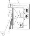
この情報入力装置1は、画像表示手段40を構成する結像手段10、画像データを供給するための映像制御手段30及び映像制御手段30からの画像データに基づいて結像手段10前面に画像を投影するための投影手段20と、結像手段10表面に沿って光LEを発し、位置測定対象物である指示部Pに反射される反射光LRを受光して指示部Pの位置を検出する位置検出手段60と、所定時間指示部Pの位置が予め定められた入力領域に位置するか否かを判定し、所定時間位置する場合には、この位置情報を有効なものとして出力する位置情報判定手段70と、位置情報判定手段70から出力される位置情報に基づいて位置検出手段60からの位置情報に基づいて結像手段10に映し出す画像を映像制御手段30に指令する全体制御手段80とを有している。
The
結像手段10,映像制御手段30,投影手段20,全体制御手段80はそれぞれ、前述の第1の実施の形態における結像手段10,映像制御手段30,投影手段20、全体制御手段80と同様であるので、これらについての説明は省略する。 The imaging means 10, the image control means 30, the projection means 20, and the overall control means 80 are the same as the imaging means 10, the image control means 30, the projection means 20, and the overall control means 80, respectively, in the first embodiment described above. Therefore, description thereof will be omitted.
本実施の形態における位置検出手段60は、指向性のある光(発射光)LEを結像手段10表面上に沿って、結像手段10表面をスキャンするように発射し、この発射光LEが指示部Pに反射して返ってくる反射光LRを受光する。位置検出手段60は、発射光LEの発射方向及び反射光LRの光量に基づいて、指示部Pの位置検出手段60に対する方向及び距離を求め、これら方向及び距離から指示部Pの位置を求めて位置情報を出力する機能を有する。
The position detecting means 60 in the present embodiment emits directional light (emitted light) LE along the surface of the imaging means 10 so as to scan the surface of the imaging means 10, and the emitted light LE is The reflected light LR reflected and returned from the instruction unit P is received. The
図4は、第2の実施の形態にかかる情報入力装置1の別の構成例を示すブロック図である。この例では、映像表示手段30と、この映像表示手段30から供給される画像データに従って画像を表示するディスプレイ手段10’によって画像表示手段40が構成されている点で、図3に示す情報入力装置1と異なっているが、その他の点については同様である。すなわち、図4に示す構成よっても、図3に示す情報入力装置1と同様の装置が構成できる。
FIG. 4 is a block diagram illustrating another configuration example of the
次に、本発明にかかる実施例について説明する。
[1.第1の実施例]
図5は、本発明にかかる情報入力装置情報入力装置1を利用したゲーム機の外観斜視図である。ここでは、ゲーム機は、バカラゲームをユーザに遊戯させる装置であるとして説明するが、本実施例にかかるゲーム機は、バカラゲームに限られず、ポーカー、ブラックジャック、ブリッジ、ルーレットなど本発明にかかる情報入力装置1を適用可能なゲームであればどのようなものであってもかまわない。
本実施例におけるゲーム機500は、テーブル部501と、テーブル部501上の後方に載置された正面ディスプレイ502とを有している。
Next, examples according to the present invention will be described.
[1. First Example]
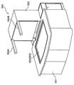
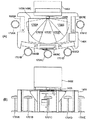
FIG. 5 is an external perspective view of a game machine using the information input device
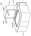
A
テーブル部501は情報入力装置1を構成する光学系及び情報処理機器を格納している。テーブル部501上面中央には、開口が設けられており、この開口には結像手段10である透過性スクリーン503が張られている。この透過性スクリーン503は、画像表示手段40である、ユーザにゲーム画像を表示するための上面ディスプレイ(以下、「テーブルスクリーン505」という)として機能する。なお、透過性スクリーン503上方は、ガラスパネルなどの透明板部材により保護されており、プレイヤがテーブルスクリーン505に指示部Pである手で触れても透過性スクリーン503が破れたり汚損しない様になっている。
The
正面ディスプレイ502の上部両端には、光源LSである蛍光灯504A、504Bが設けられており、透過性スクリーン503に指示部Pの影PSが射影されるようになっている。なお、蛍光灯504A、504Bの配置位置は必ずしも図5に示す態様でなくとも良く、透過性スクリーン503に指示部Pの影PSが射影される様な配置位置であればどの位置に設置されていてもかまわない。また、ゲーム機500が設置される場所に透過性スクリーン503に指示部Pの影PSが射影される様な照明が設けられていれば、蛍光灯504A、504Bは設けなくともかまわない。
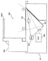
図6は、テーブル部501内部に格納されている情報入力装置1を構成する光学系の配置例を示す図である。
テーブル部501の中央部には、透過性スクリーン503がガラスプレートなどにより保護された状態で固定されている。透過性スクリーン503の下方にはミラー601が傾斜した状態で設置されている。ミラー601に対向する位置に、投影手段20に相当するデジタル液晶プロジェクタ(以下、DLP)602と、撮像手段50に相当するデジタルビデオカメラ(DVC)603が固定されている。ミラー601はDLP602から照射された画像を透過性スクリーン503に向けて反射し、画像を所望の大きさで映し出すように、DLP602との距離、反射面の角度が調整されている。同様に、ミラー601は、透明スクリーン503背面の画像をデジタルビデオカメラ603に向けて反射し、デジタルビデオカメラ603が透明スクリーン503背面を撮像できるようにデジタルビデオカメラ603との距離および透明スクリーン503/デジタルビデオカメラ603に対する反射面の角度が調整されて設置されている。
FIG. 6 is a diagram illustrating an arrangement example of the optical systems constituting the
A
次に、ゲーム機500の電気的構成例について説明する。図7は、ゲーム機500の電気的構成例を示すブロック図である。
図7に示すように、ゲーム機500は、透過性スクリーン503が設けられている。投影手段20であるDLP602は、この透過性スクリーン503にゲームに関する画像を光学的に投射する。映像制御手段30であるスクリーン画面制御部701は、DLP602に画像データ(以下、「前面画像データ」と呼ぶ)を供給する。撮像手段50であるデジタルビデオカメラ603は、透過性スクリーン503背面を撮影し、透過性スクリーン503背面の撮影により得られた画像データ(以下、「背面画像データ」と呼ぶ)を出力する。位置検出手段60である位置検出部704は、この背面画像データを処理することにより、指示部Pにより指示された位置を検出し、位置情報を出力する。位置情報判定手段70である位置情報判定部703は、位置情報に基づいて、指示部Pが所定時間一定の領域にあるか否かを判定し、所定時間一定の領域にあると判定した場合は、その位置情報を有効なものとして出力する。全体制御手段80であるゲーム制御部702は、ゲーム機500の動作を制御する機能を有し、スクリーン画面制御部701にどの画像データをどのタイミングで出力させるかなどの指令を行うとともに、位置検出部704からの位置情報を受け取り、この位置情報に基づいて、ゲーム機500の動作を制御する。
Next, an example of the electrical configuration of the
As shown in FIG. 7, the
正面ディスプレイ制御部705は、ゲーム制御部702からの指令に応じて、正面ディスプレイ502に表示する画像の画像データ(以下、「正面画像データ」と呼ぶ)を出力する。正面ディスプレイ502は、この正面画像データを受け取り、表示する。正面ディスプレイ502に表示される画像は、透過性スクリーン503に表示される画像と相まって、ゲームの状況、進行具合などをユーザに知らしめる。
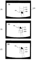
The front
この実施例では、正面ディスプレイ502には、バカラのディーラーが動画により表示される。図8は、正面ディスプレイ502に表示される画面例である。画面には、ディーラー801が表示されており、ゲームの進行に従ってカードの配布、ドロウ、チップの受け渡し動作を行う様子が表示され、プレイヤがあたかも実際のディーラーとバカラゲームを行っているような演出が行われる。
In this embodiment, a baccarat dealer is displayed as a moving image on the
次に、画像表示手段40であるテーブルスクリーン505(透過性スクリーン503)に表示される画面例を示す。図9は、ゲーム機500のテーブルスクリーン505(透過性スクリーン503)に表示される画面例である。この実施例では、テーブルスクリーン505にはバカラテーブルを模した画面が表示される。この例に示すバカラテーブルには、5人のプレイヤそれぞれについて、「BANKER」「PLAYER」「引き分け」にかけるための領域901、902、903が表示される。プレイヤが指示部Pである手などによって、領域901、902、903の何れかを指し示すことにより、そのプレイヤが「BANKER」「PLAYER」「引き分け」のいずれにベットするかがゲーム機500に入力されることとなる。なお、ベットするチップの枚数/金額/クレジット数は、後述のプレイヤ端末部706のベットボタンによってプレイヤが決定できるようになっている。各プレイヤが所有するチップの山906もテーブルスクリーン505に表示されており、プレイヤが「BANKER」「PLAYER」「引き分け」のいずれにベットするかを指示部Pにより指示すると、手元のチップの山から指定した領域901、902、903のいずれかへベットした枚数のチップだけ移動するように、テーブルスクリーン505に表示される画像が変化するようになっている。
Next, an example of a screen displayed on the table screen 505 (transparent screen 503) which is the image display means 40 is shown. FIG. 9 is an example of a screen displayed on the table screen 505 (transparent screen 503) of the
また、テーブルスクリーン505には、ディーラー801がBANKER、PLAYERのカードを配布する領域904,905があり、この領域904,905には、カードの画像が表示される。
The
図7に戻り、ゲーム機500の電気的構成例の説明を続ける。
ゲーム制御部702には、複数のプレイヤ端末部7061〜706Nが接続されている。各プレイヤ端末部706は、プレイヤが貨幣、紙幣、プリペイドカード、クレジットカードなどを受け取り、これをゲーム機500で使用するクレジット(メダル/コイン)として扱えるようにするとともに、プレイヤからの払出指示に応じてその時点で所有しているクレジット(メダル/コイン)の払出を行うビルバリ機能、およびゲームにおけるベットの枚数/金額/クレジット数を決定するベット入力機能を有する端末機である。プレイヤはこのプレイヤ端末部706と指示部Pによりゲームを進行させるための入力を行うこととなる。
Returning to FIG. 7, the description of the electrical configuration example of the
A plurality of
次に、透過性スクリーン503背面の背面画像データから指示部Pである手の位置を検出する処理について説明する。
図10(A)は、透過性スクリーン503に指示部Pの影PSが投影されていない状態で、ビデオカメラ(DVC)603がミラー601を介して透過性スクリーン503背面を撮像した画像の例である。ビデオカメラ603は、透過性スクリーン503だけでなく、透過性スクリーン503周囲を囲む周辺部1000も撮像するように調整されている。周辺部1000は、たとえばスクリーン503をテーブル部天板に固定するための固定枠であって、望ましくは黒若しくは黒に近い暗色に着色されている。
Next, a process for detecting the position of the hand as the instruction unit P from the back surface image data on the back surface of the
FIG. 10A is an example of an image in which the video camera (DVC) 603 images the back of the
肉眼で見た場合は、透過性スクリーン503背面からも、図9に示すような透過性スクリーン503前面に表示される画像(ゲームテーブル)も薄く見えることがある。そこで、ビデオカメラ603の露出を調整して透過性スクリーン503前面に表示される画像が白く飛んでしまうように設定する。なお、ビデオカメラ603が自動露出調整機能を有している場合には、露出が黒若しくは黒に近い暗色に着色されている周辺部1000に合わせて調整されるため、特に露出調整を行わなくとも自動的に透過性スクリーン503前面に表示される画像を排除することが可能となる。
When viewed with the naked eye, an image (game table) displayed on the front surface of the
図10(B)は、透過性スクリーン503に指示部Pの影PSが投影された状態で、ビデオカメラ603がミラー601を介して透過性スクリーン503背面を撮像した画像の例である。この画像では、指示部Pである手の影PSが透過性スクリーン503にある。この例では、影PSは、濃い影である本影PS1と薄い影である半影PS2となっている。本影PS1と半影PS2は透過性スクリーン503との距離の差による。透過性スクリーン503により近い手の前方部分(手先側)の影は本影PS1となり、透過性スクリーン503から離れる手の後方部分(腕側)の影は半影PS2となる。この影の濃淡の違いにより、指示部Pの先端を判別することができる。
FIG. 10B is an example of an image in which the
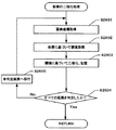
図11は、本ゲーム機500が背面画像データを用いて指示部Pの位置検出を行う位置検出処理の例を示すフロー図である。
まず、ゲーム機500は、スクリーン背面撮像処理を行う(ステップS1101)。すなわち、ビデオカメラ603は、ミラー601を介して透過性スクリーン503背面を撮像し、図10(B)に示す様な画像を背面画像データとして位置検出部704に出力する。
FIG. 11 is a flowchart illustrating an example of a position detection process in which the
First, the
位置検出部704は、背面画像データを受け取ると、この背面画像データを二値化処理する(ステップS1102)。図10(C)は、二値化処理後の背面画像データを表示した場合のイメージ図である。指示部Pの影PSは、半影PS2などの薄い部分が捨象され、指示部Pの先端部が残り、指示部Pによりどの位置が指し示されているのかが明確になる。二値化処理を行う場合には、指示部Pの先端部を特定できるよう、適宜な閾値を設定する。閾値はゲーム機500周辺の環境(周辺照明の明るさなど)により適切な値が変化するため、ゲーム機500の設置した後可動テストを行い適切な値を探すようにすればよい。
Upon receiving the back image data, the
次に、位置検出部704は、二値化処理後の背面画像データから位置検出処理を行う(ステップS1103)。位置検出部704は、二値化処理後の背面画像データから黒の値を有するピクセルの座標値(x、y値)を取得し、これに基づいて位置情報を生成する。位置情報は、先端部頂点となるピクセルの座標値であってもよいし、黒の値を有するピクセル全部の座標値の平均、中央値などを選択するようにすればよい。位置検出処理が終了すると、位置検出部704は、ステップS1103において生成した位置情報を位置情報判定部703に出力する。
Next, the
位置検出部704から位置情報を受け取った位置情報判定部703は、位置情報判定処理を行う(ステップS1104)。図12は、位置情報判定処理を説明するための一連の透過性スクリーン503背面の画像の例である。図12(A)は、予め定めた閾値に基づく二値化処理を行った背面画像の例である。このとき、指示部Pの先端部の影PSは、予め定められた入力領域の一つである領域903(図9参照)内に位置している。
The position
図12(B)は、図12(A)に示す画像撮影から所定時間経過した時点における透過性スクリーン503背面の画像の例である。このとき、プレイヤはさらに指示部Pをのばして予め定められた別の入力領域である領域901を指示している。位置情報判定部703は、図12(A)と図12(B)の撮影時における指示部Pの位置情報が同一の入力領域にないと判定し、いずれの時点の位置情報も出力しない。
FIG. 12B is an example of an image on the back surface of the
図12(C)は、図12(B)に示す画像撮影から所定時間経過した時点における透過性スクリーン503背面の画像の例である。このとき、プレイヤは指示部Pを予め定められた入力領域である領域901を指示し続けている。位置情報判定部703は、図12(B)と図12(C)の撮影時における指示部Pの位置情報が同一の入力領域901にあると判定し、図12(B)又は図12(C)における指示部Pの位置情報を出力する。なお、指示部Pの位置情報の代わりに、入力領域を示す情報(例えば入力領域ID)を出力する構成としてもかまわない。
FIG. 12C is an example of an image on the back surface of the
位置情報判定部703は、位置情報判定処理を行った結果、有効な位置情報であると判定した場合には、その位置情報をゲーム制御部702に渡し、位置情報出力処理を行う(ステップS1105)。一方、位置情報が有効であると判定しない場合には、位置情報判定部703は位置情報の出力を行わない。
If the position
ゲーム制御部702は、位置情報判定部703から受け取った位置情報に基づいて、その位置情報が示す入力領域に応じた所定の処理、例えば画像表示処理などを行う(ステップS1106)。たとえば、ゲーム制御部702は、その位置情報を「BANKER」「PLAYER」「引き分け」にかけるための領域901、902、903の何れかの指定と判断して、当該領域内へ、指定されたチップの山906の画像を表示するように、制御を行う。
Based on the position information received from the position
上述の通り、結像手段10である透過性スクリーン503を情報入力装置1として利用するゲーム機500が実現できる。
As described above, the
図13に、ゲーム機500の変形例を示す。この変形例では、ビデオカメラ603は、テーブルスクリーン505上方から指示部Pの影ではなく、その実像を含む画像を撮影し、位置検出部704は実像から指示部Pによって指し示された位置を判定する。その他の構成要素及び動作については、図7に示すゲーム機500と同様である。
FIG. 13 shows a modified example of the
[2.第2の実施例]
次に、本発明にかかる第2の実施例について説明する。
図14は、第2の実施の形態にかかる情報入力装置1を利用したゲーム機1400の外観斜視図である。ここでは、ゲーム機は、バカラゲームをプレイヤに遊戯させる装置であるとして説明するが、本実施例にかかるゲーム機は、バカラゲームに限られず、ポーカー、ブラックジャック、ブリッジ、ルーレット、サッカーゲーム、アメリカンフットボールゲーム、RPG、アクションゲームなど本発明にかかる情報入力装置1を適用可能なゲームであればどのようなものであってもかまわない。
[2. Second embodiment]
Next, a second embodiment according to the present invention will be described.
FIG. 14 is an external perspective view of a
本実施例におけるゲーム機1400は、テーブル部1401と、テーブル部1401上の後方に載置された正面ディスプレイ1402とを有している。
テーブル部1401は情報入力装置1を構成する光学系及び情報処理機器を格納している。テーブル部1401上面中央には、開口が設けられており、この開口には結像手段10である透過性スクリーン1403が張られている。この透過性スクリーン1403は、画像表示手段40である、プレイヤにゲーム画像を表示するための上面ディスプレイ(「テーブルスクリーン」ともいう)として機能する。なお、透過性スクリーン1403上方は、ガラスパネルなどの透明板部材により保護されており、プレイヤが上面ディスプレイに指示部Pである手で触れても透過性スクリーン1403が破れたり汚損しない様になっている。
A
The
正面ディスプレイ1402の上部両端には、蛍光灯1404A、1404Bが設けられている。なお、蛍光灯1404A、1404Bの配置位置は必ずしも図13に示す態様でなくとも良く、どの位置に設置されていてもかまわない。また、ゲーム機1400が設置される場所に十分な照明が設けられていれば、蛍光灯1404A、1404Bは設けなくともかまわない。
正面ディスプレイ1402の中央下側には、位置検出手段60であるセンサ1405が設けられている。センサ1405は、例えば障害物検知用光電センサ(北陽電機株式会社(大阪市)、PB9シリーズ)、レーザセンサなどである。センサ1405は、上記の配置位置に限られず、テーブルスクリーン505である透過性スクリーン1403表面に沿って走査光を発し、透過性スクリーン1403上方を走査できる位置に配置されればよい。
A
図14は、テーブル部1401内部に格納されている情報入力装置1を構成する光学系の配置例を示す図である。
テーブル部1401の中央部には、透過性スクリーン1403がガラスプレートなどにより保護された状態で固定されている。透過性スクリーン1403の下方にはミラー1501が傾斜した状態で設置されている。ミラー1501に対向する位置に、投影手段34に相当するデジタル液晶プロジェクタ(以下、DLP)1502が固定されている。ミラー1501はDLP1502から照射された画像を透過性スクリーン1403に向けて反射し、画像を所望の大きさで映し出すように、DLP1502との距離、反射面の角度が調整されている。
FIG. 14 is a diagram showing an arrangement example of the optical system constituting the
A
また、テーブル部1401の上面には、透過性スクリーン1403上方を走査光1503により、走査できるようセンサ1405が設置されている。
A
次に、ゲーム機1400の電気的構成例について説明する。図16は、ゲーム機1400の電気的構成例を示すブロック図である。
図16に示すように、ゲーム機1400には、結像手段10である透過性スクリーン1403が設けられている。投影手段20であるDLP1502は、この透過性スクリーン1403にゲームに関する画像を光学的に投射する。映像制御手段30であるスクリーン画面制御部1601は、DLP1502に画像データ(以下、「前面画像データ」と呼ぶ)を供給する。透過性スクリーン1403,スクリーン画面制御部1601、及びDLP1502は、画像表示手段40であるテーブルスクリーン1406を構成する。位置検出手段60であるセンサ1405は、指示部Pにより指示された位置を検出し、位置情報を出力する。位置情報判定手段70である位置情報判定部1603は、位置情報に基づいて、指示部Pが所定時間一定の領域にあるか否かを判定し、所定時間一定の領域にあると判定した場合は、その位置情報を有効なものとして出力する。全体制御手段80であるゲーム制御部1602は、ゲーム機1400の動作を制御する機能を有し、スクリーン画面制御部1601にどの画像データをどのタイミングで出力させるかなどの指令を行うとともに、位置情報判定部1603からの位置情報を受け取り、この位置情報に基づいて、ゲーム機1400の動作を制御する。
Next, an example of the electrical configuration of the
As shown in FIG. 16, the
正面ディスプレイ制御部1604は、ゲーム制御部1602からの指令に応じて、正面ディスプレイ1402に表示する画像の画像データ(以下、「正面画像データ」と呼ぶ)を出力する。正面ディスプレイ1402は、この正面画像データを受け取り、表示する。正面ディスプレイ1402に表示される画像は、透過性スクリーン1403に表示される画像と相まって、ゲームの状況、進行具合などをプレイヤに知らしめる。この例では、正面ディスプレイ1402には、第1の実施例と同様に、図8に示すようなバカラのディーラーが動画により表示される。
The front
正面ディスプレイ1402に表示される画像は、センサ1405によって検出される位置情報に基づいて制御されるようにしても良い。例えば、正面ディスプレイ1402に表示されるディーラーは、位置情報に従ってその位置に正対するように顔・身体の向きを変化させるように表示される。
The image displayed on the
テーブルスクリーン1406には、第1の実施例と同様に、図9に示すような表示される画面が表示される。すなわち、テーブルスクリーン1406にはバカラテーブルを模した画面が表示される。この例に示すバカラテーブルには、5人のプレイヤそれぞれについて、「BANKER」「PLAYER」「引き分け」にかけるための領域901、902、903が表示される。プレイヤが指示部Pである手などによって、領域901、902、903の何れかを指し示すことにより、そのプレイヤが「BANKER」「PLAYER」「引き分け」のいずれにベットするかがゲーム機1400に入力されることとなる。
なお、ベットするチップの枚数/金額/クレジット数は、後述のプレイヤ端末部1605のベットボタンによってプレイヤが決定できるようになっている。各プレイヤが所有するチップの山もテーブルスクリーン1406に表示可能であり、プレイヤが「BANKER」「PLAYER」「引き分け」のいずれにベットするかを指示部Pにより指示すると、手元のチップの山から、指示部Pにより指定した領域901、902、903のいずれかへベットした枚数のチップだけ移動するように、テーブルスクリーン1406に表示されるよう、画像が変化するようになっている。
On the
The number of chips to bet / the amount of money / the number of credits can be determined by the player using a bet button on the
図16に戻り、ゲーム機1400の電気的構成例の説明を再開する。
ゲーム制御部1602には、複数のプレイヤ端末部16051〜1605Nが接続されている。各プレイヤ端末部1605は、プレイヤが貨幣、紙幣、プリペイドカード、クレジットカードなどを受け取り、これをゲーム機1400で使用するクレジット(コイン/メダル)として扱えるようにするとともに、プレイヤからの払出指示に応じてその時点で所有しているクレジット(コイン/メダル)の払出を行うビルバリ機能、およびゲームにおけるベットの枚数/金額/クレジット数を決定するベット入力機能を有する端末機である。プレイヤはこのプレイヤ端末部1605と指示部Pによりゲームを行うこととなる。
Returning to FIG. 16, the description of the electrical configuration example of the
A plurality of
次に、指示部Pであるプレイヤの手によって指し示される、テーブルスクリーン1406上のある位置を検出する処理について説明する。
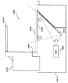
図17(A)は、ゲーム機1400を上方から見下ろした平面図であって、ゲーム機1400に設けられたセンサ1405がテーブルスクリーン1406上を走査する様子を示しており、図17(B)は、図17(A)に対応するゲーム機1400の正面図である。
Next, processing for detecting a certain position on the
FIG. 17A is a plan view of the
センサ1405は、テーブルスクリーン1406上を通過するように走査光を発射する。センサ1405は、センサ1405を中心として走査光を右から左へ、或いは左から右へ回動させてテーブルスクリーン1406上全域を走査する。例えば、センサ1405は、走査光の発射方向を0.5度刻みで旋回させながら、走査光の発射と反射光の受光を繰り返す。
The
本実施の形態では、センサ1405の位置検出により、どのプレイヤによる位置の指示であるかを判定することも可能である。ゲーム機1400には、最大5名のプレイヤが着座可能なスツール1701A〜1701Eが設けられており、各プレイヤの手が届く領域は限定されるようになっている。各プレイヤの着座位置前方には、テーブル部1401に組み込まれたプレイヤ端末部1605A〜1605Eが設けられている。プレイヤ端末部1605A〜1605Eはそれぞれ、ベットボタン、キャンセルボタン、払出ボタン(図略)などが設けられており、プレイヤからの入力指示を受け付けるようになっている。
In this embodiment, it is also possible to determine which player is instructing the position by detecting the position of the
図17(A)に示す領域1702A〜1702Eは、各プレイヤの手が届く領域である。たとえば領域1702Aはスツール1701Aを利用するプレイヤの手が届く領域となる。領域1702A内においてテーブルスクリーン1406上のある位置が指し示された場合は、それはスツール1701Aを利用するプレイヤによって指し示された位置であると、判定するようになっている。センサ1405は、走査光の発射方向に基づいてどの領域1702A〜1702Eで位置検出がなされたかを判定し、その領域に対応するプレイヤによる位置指示と判定し、位置情報とともに対応するプレイヤを特定する情報(例えば、プレイヤ番号)を位置情報判定部1603に送る。
図18は、領域1702Bにおいてプレイヤが位置を指し示した状態を示す。プレイヤは指示部Pである手1801によりテーブルスクリーン1406上の領域1702B内のある位置を指し示している。センサ1405は、指し示された位置を検出し、その位置が領域1702B内であることに基づいて、その指し示された位置はプレイヤ(スツール1701Bに着座し、プレイヤ端末部1605Bを利用するプレイヤ)によるものと判断する。図19は、領域1702Cにおいてプレイヤが位置を指し示した状態を示す。プレイヤは指示部Pである手1901によりテーブルスクリーン1406上の領域1702C内のある位置を指し示している。センサ1405は、指し示された位置が領域1702B内であることに基づいて、その指し示された位置はプレイヤ(スツール1701Cに着座し、プレイヤ端末部1605Cを利用するプレイヤ)によるものと判断する。
FIG. 18 shows a state where the player points to a position in the
この方法によれば、各プレイヤの使用するチップの色(例えば、赤、青、黄、緑、白)をそれぞれ定めて、検出した位置情報に基づいてその位置情報の示すテーブルスクリーン1406上の場所に表示させることも可能となる。
According to this method, the chip color (for example, red, blue, yellow, green, white) used by each player is determined, and the location on the
なお、本実施例では、一個のセンサ1405によってテーブルスクリーン1406上の全領域を走査する構成として説明したが、センサ1405を複数設けて各センサ1405にテーブルスクリーン1406上の割り当てられた領域を走査させる構成としても、本発明は成立する。例えば、2個のセンサ1405を設けて、一方のセンサ1405にはテーブルスクリーン1406上の右半分の領域を担当させ、他方のセンサ1405にはテーブルスクリーン1406上の左半分の領域を担当させる構成としても良い。
In the present embodiment, a description has been given of a configuration in which the entire area on the
上記位置検出方法によれば、同時に複数のプレイヤがテーブルスクリーン1406上の位置を指し示した場合でも、それぞれの指し示された位置と対応するプレイヤを認識することが可能となる。
According to the position detection method described above, even when a plurality of players point to a position on the
図20は、センサ1405により指示部Pの位置検出を行う位置検出処理の例を示すフロー図である。
まず、センサ1405が位置検出処理をおこなう(ステップS2001)。センサ1405は、走査光によりテーブルスクリーン1406上をスキャンし、指示部Pによる走査光の反射があるかどうかを判定し、反射がある場合はその反射光の強度や光量を測定し、方向及び距離を特定して指示部の位置算出をおこなう。次に、センサ1405は、算出した位置を位置情報(例えば、xy座標値)として位置情報判定部1603に出力する。センサ1405は位置情報とともにこの位置情報に対応するプレイヤ識別情報(例えば、プレイヤ番号)を出力するようにしても良い。
FIG. 20 is a flowchart illustrating an example of position detection processing in which the position of the instruction unit P is detected by the
First, the
次に、位置情報判定部1603は、位置情報を受け取ると、位置情報判定処理を行う(ステップS2002)。すなわち、位置情報判定部1603は、指示部Pが所定時間一定の領域にあるか否かを判定し、所定時間一定の領域にあると判定した場合は、その位置情報を有効なものとして出力する。例えば、位置情報判定部1603は、位置情報X1を受け取るとそれを記憶しておく。位置情報判定部1603は、所定時間T経過後に新たな位置情報X2を受け取ると、位置情報X1及びX2の座標値が同一の入力領域(例えば、領域901,902,903)にあるか否かを判定する。
Next, upon receiving the position information, the position
位置情報判定部1603は、位置情報判定処理においてその位置情報を有効と判定した場合に、位置情報出力処理を行う(ステップS2003)。位置情報判定処理においてその位置情報を有効でない判定した場合には、位置情報出力処理は行わない。
If the position
位置情報出力処理によって位置情報判定部1603から出力された位置情報はゲーム制御部1602に渡される。ゲーム制御部1602は、受け取った位置情報に基づいてどのような画像をテーブルスクリーン1406及び/又は正面ディスプレイ1402に表示するかを決定し、画像表示処理を行なわせる(ステップS2004)。たとえば、その位置情報を「BANKER」「PLAYER」「引き分け」にかけるための領域901、902、903の何れかの指定と判断して、当該領域内へ、指定されたチップ画像を表示するように、スクリーン画面制御部1601に指令し、スクリーン画面制御部1601はこの指令に応じて画像データの生成を行う。
The position information output from the position
上述の通り、本実施例によれば、テーブルスクリーン1406を画像表示手段兼入力手段として利用するゲーム機1400が実現できる。
As described above, according to the present embodiment, the
[実施例の変形]
第1の実施例において、ゲーム機500がプレイヤの入力の回数を取得できるようにしても良い。ゲーム機においては、プレイヤが同一の領域を素早く複数回叩く(タップする)ことを特定の処理の要求として解釈するものがある。例えば、一回タップの場合はその場所を賭け位置として選択し、二回タップの場合は賭け位置のキャンセルという処理をすることが考えられる。
[Modification of Example]
In the first embodiment, the
第1の実施例では、位置情報判定部703が所定時間における影PSの濃淡の変化に基づいて、入力の回数を判定する構成としても良い。図21は、影PSの濃淡の変化に基づいて、入力の回数を判定する場合の画面例を示す。図21(A)から(C)は、所定期間内の連続した背面画像の例を示す。図21(A)において、プレイヤが一回目のタップを行ってテーブルスクリーン505に手を接触した場合の2値化処理後の画像イメージ、図21(B)は、プレイヤが二回目のタップを行うためテーブルスクリーン505から手を離した場合の2値化処理後の画像イメージ、図21(C)は、プレイヤが二回目のタップを行ってテーブルスクリーン505に手を接触した場合の2値化処理後の画像イメージである。所定期間内におこる同一の入力領域内の影PSの濃淡(有無)をカウントして、これをタップ回数として認識し、ゲーム制御部703にタップ回数の情報を渡すようにしても良い。ゲーム制御部703は、タップ回数に応じた所定の処理を行う。
In the first embodiment, the position
[3.第3の実施例]
次に、第3の実施例について説明する。
第3の実施例は、第1の実施例にかかるゲーム機500であって、プレイヤが自己の入力領域である「BANKER」「DRAW」「PLAYER」の内、複数の領域にかかるように腕を伸ばした場合であっても、プレイヤの意図するところを正しく認識させることができ、誤認識を防止するゲーム機500を実現するものである。なお、第3の実施例にかかるゲーム機500の構成及び動作は、基本的に第1の実施例にかかるゲーム機500と同様であるので、これらの詳細な説明は省略する。
[3. Third Example]
Next, a third embodiment will be described.
The third embodiment is a
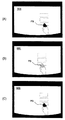
図22(A)〜(C)は、ゲーム機500のプレイヤであって、ゲーム機500に向かって右から2番目のプレイヤが、自己の領域である入力領域901〜903に手を伸ばして、自己の希望する領域の指定を行っている図である。図22(A)は、一番手前に位置する領域903を指定している図であり、図22(B)は、中間に位置する領域902を指定している図であり、図22(C)は、一番奥に位置する領域901を指定している図である。
22A to 22C are players of the
図23(A)〜(C)は、図22(A)〜(C)に対応する透過性スクリーン503背面を撮影した画像の例を示す図である。図23(A)の例では、領域903内にのみ影PSが存在する。そのため、ゲーム機500はプレイヤによって領域903が指定されたものと判断する。図23(B)の例では、領域902,および903内に影PSが存在する。そのため、プレイヤが指定した領域は領域902であるのに、ゲーム機500はプレイヤによって領域902、903が同時に選択されたと判断してしまう虞がある。また、図23(C)の例では、領域901,902,および903内に影PSが存在する。そのため、プレイヤが指定した領域は領域901であるにもかかわらず、ゲーム機500はプレイヤによって領域901,902、903が同時に選択されたと判断してしまう虞がある。
FIGS. 23A to 23C are diagrams illustrating examples of images obtained by photographing the back surface of the
上記のような複数の領域が同時に指定されたと誤認識することを回避するために、第3の実施例にかかるゲーム機500の位置情報判定部703は、その動作の一つの処理である位置情報判定処理(ステップS1104)において、図24に示すような位置情報判定処理を行う。図24は、第3の実施例にかかる位置情報判定部703の、位置情報判定処理の一例を示すフロー図である。
In order to avoid misrecognizing that a plurality of areas as described above are designated at the same time, the position
まず、位置情報判定部703は影があるかどうかを判定する入力領域(領域)を特定する(ステップS2401)。次に、特定した入力領域に関連づけされた、関連入力領域を特定する(ステップS2402)。関連入力領域は、ある入力領域がプレイヤによって指定された場合に、その指定に伴って影が形成される可能性のある入力領域であって、たとえば図23に示す同一列に属する領域901,902、903は互いに他の入力領域の関連入力領域となる。どの入力領域が関連入力領域であるかは、予めテーブルとして位置情報判定部703に記憶されている。
First, the position
たとえば、図23(A)〜(C)の例では、ステップ2401で領域903を入力領域として特定すると、ステップS2402においてその関連入力領域として領域901,902が特定される。
For example, in the example of FIGS. 23A to 23C, when the
次に、位置情報判定部703は特定された入力領域、及びその関連入力領域に影があるか否かを判定する(ステップS2403)。いずれの入力領域にも影がない場合(ステップS2403,No)は、位置情報判定部703は透過性スクリーン503(テーブルスクリーン505)内のすべての入力領域(関連入力領域含む)について判定を行ったか否かを判定し(ステップS2408)、透過性スクリーン503(テーブルスクリーン505)内のすべての入力領域について判定している場合(ステップS2408、Yes)は、位置情報判定処理を終了して図11に示す処理に戻り、一方、透過性スクリーン503(テーブルスクリーン505)内のすべての入力領域については判定していない場合(ステップS2408、No)は、透過性スクリーン503(テーブルスクリーン505)内の未判定入力領域のいずれかに移行する(ステップS2409)。
Next, the position
さて、ステップS2403において、いずれかの入力領域に影ある場合(ステップS2403,Yes)は、位置情報判定部703は入力領域(関連入力領域含む)の内、影を含む入力領域は複数か否かを判定する(ステップS2404)。影を含む入力領域が複数でない場合(ステップS2404,No)は、位置情報判定部703はその影を含む入力領域の影の存在を有効と判断する(ステップS2406)。例えば、図23(A)に示す例では、領域901〜903である3つの入力領域(関連入力領域含む)の内、領域903のみが影を含んでいる。位置情報判定部703は領域903の影を有効と判断する(ステップS2405)。その結果、領域903がプレイヤによって指定されたと判定されることとなる。
In step S2403, if any input area has a shadow (Yes in step S2403), the position
一方、ステップS2404において、影を含む入力領域が複数であると判定された場合(ステップS2404、Yes)は、位置情報判定部703はその影を含む入力領域の内、最上位である入力領域の影の存在を有効と判断(ステップS2406)し、他の入力領域の影を無効として判断する(ステップS2407)。関連入力領域は互いに順位が定められており、位置情報判定部703に記憶されている。図22(A)〜(C)、図23(A)〜(C)に示す例では、領域である3つの入力領域901〜903は、領域901が最も順位が高く、領域902が領域901に次いで順位が高く、領域903は最も順位が低いと定められる。したがって、図23(B)に示す例では、領域902,903に影が存在しているので、ステップS2406において順位の高い領域902の影を有効と判定され、ステップS2407において他の入力領域である領域903の影は無効と判定される。その結果、領域902のみがプレイヤによって指定されたと判定されることとなる。図23(C)の例の場合も、同様の処理方法によって、ステップS2406において最も順位の高い領域901の影を有効と判定され、ステップS2407において他の入力領域である領域902,903の影は無効と判定される。その結果、領域902,903の影に影響されることなく領域901のみがプレイヤによって指定されたと判定されることとなる。
On the other hand, when it is determined in step S2404 that there are a plurality of input areas including shadows (step S2404, Yes), the position
[4.第4の実施例]
次に、本発明の第4の実施例について説明する。
第4の実施例は、第1の実施例にかかるゲーム機500であって、プレイヤの指示位置を示す影を、透過性スクリーン503上の位置に応じて定められた閾値に基づいて判定し、この閾値は、DLP602からの距離又は、透過性スクリーン503上の照度に応じて定められるゲーム機500を実現するものである。なお、第4の実施例にかかるゲーム機500の構成及び動作は、基本的に第1の実施例にかかるゲーム機500と同様であるので、これらの詳細な説明は省略する。
[4. Fourth Example]
Next, a fourth embodiment of the present invention will be described.
The fourth embodiment is a
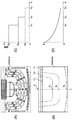
透過性スクリーン503はDLP602によって画像を映し出すために照射されており、その表面はDLP602からの照射光の中心に近づくほど明るく、中心から離れるに従って暗くなる。従って、透過性スクリーン503に形成される影PSもこのDLP602の照射光の影響を受けて、照射の中心では照射光に相殺されて影の濃さは薄く、中心から離れるに従って照射光の影響が少なくなり影の濃さが濃くなる。このような照射光の影響のため、透過性スクリーン503表面(前面、背面のいずれでも良い)のすべての位置について、影の有無の判定を行うための閾値を一定に定める構成とすると、DLP602の照射の中心に近づくほど影の存在が判定されづらく、一方中心から離れるに従って影の存在が判定されやすくなる虞がある。そこで、閾値は照射光の中心からの距離又は透過性スクリーン503上の照度に応じて定める様にして、このDLP602からの照射光の影響を考慮して影の存在判定を行う。
The
図25(A)は、透過性スクリーン503表面にDLP602から画像が投影されている様子を示している。図25(B)は、図25(A)の透過性スクリーン503について、DLP602からの照射光の中心からの距離に応じて影の存在の判定を行うための閾値が3つの領域に分かれて定められている様子を示している。図25(B)においてDLP602からの照射光の中心は、原点Oにあり、この原点Oに近い領域から領域E1、E2、E3が定められている。領域E1、E2、E3それぞれに含まれる座標位置(画素)について閾値は、それぞれS3、S2、S1(S3>S2>S1)に定められている。なお、この例では、座標位置(画素)のエネルギー(輝度など)が閾値以下であれば影であると判定し、閾値をこえていれば影でないと判定する。このような閾値の定め方により、たとえば領域E3において影と判定されない薄い影であっても、領域E1においては影と判定されるようになり、DLP602の照射光の影響を排除しながら影の存在の判定を行うこと可能としている。
FIG. 25A shows a state in which an image is projected from the
図25(C)は、図25(B)の場合において、X軸方向の閾値の変化を示す図である。
本実施例において、閾値は各領域毎に定められる閾値の定め方に限定されるものではない。図25(D)は、図25(C)とは別の閾値の定め方を示す図である。この図25(D)の例では、X軸方向の閾値の変化は連続的におおよそ逆指数的に変化するように設定されている。
FIG. 25C is a diagram showing changes in the threshold value in the X-axis direction in the case of FIG.
In the present embodiment, the threshold value is not limited to the method of determining the threshold value determined for each region. FIG. 25D is a diagram illustrating a threshold value determination method different from that in FIG. In the example of FIG. 25D, the change in the threshold value in the X-axis direction is set so as to continuously change approximately in an exponential manner.
図26は、第4の実施例における、画像の二値化処理(図11,ステップS1102)の具体例を示すフロー図である。画像の二値化処理が開始されると、位置検出部704は、二値化処理対象とする画素を特定し、その座標位置を取得する(ステップS2601)。次に、位置検出部704はその座標位置に基づいて閾値を取得する(ステップS2602)。各座標位置毎に閾値を定めたテーブルを位置検出部704は記憶しており、このテーブルを参照して座標位置に対応する閾値を取得することとなる。閾値は、DLP602からの距離或いはDLP602によるその位置の照度に応じて定められている。
FIG. 26 is a flowchart showing a specific example of the binarization processing (FIG. 11, step S1102) of the image in the fourth embodiment. When the binarization processing of the image is started, the
次に、位置検出部704はその画素のエネルギーと取得した閾値を比較して、その画素が影であるか否か(1か0か)の判定を
を行い、判定結果を記憶する(ステップS2603)。
Next, the
次に、すべての画素について判定したかをチェックし(ステップS2604)、判定していない画素が残っている場合(ステップS2605、No)は、未判定画素に移行しステップS2601以下の処理を続行する。
すべての画素について判定画終了すると、画像の二値化処理を終了し、図11に示す処理に戻ることとなる。
Next, it is checked whether or not all the pixels have been determined (step S2604). If there are remaining pixels that have not been determined (step S2605, No), the process proceeds to an undetermined pixel and the processing from step S2601 is continued. .
When the determination image is completed for all the pixels, the image binarization process is ended, and the process returns to the process shown in FIG.
本実施例によれば、この投影手段であるDLP602の照射光の影響を考慮して、影の存在判定を行うことが可能となる。
According to the present embodiment, it is possible to determine the presence of a shadow in consideration of the influence of irradiation light of the
本発明は、ゲーム機に限らず、プレゼンテーション用情報入力装置、販売促進用デモンストレーション装置、など画像表示と表示された画像を利用したユーザ入力受付を行うすべての装置若しくはシステムに適用することが可能である。 The present invention is not limited to a game machine, and can be applied to all devices or systems that accept user input using image display and displayed images, such as presentation information input devices, sales promotion demonstration devices, and the like. is there.
1 … 情報入力装置
10 … 結像手段
20 … 投影手段
30 … 映像制御手段
40 … 画像表示手段
50 … 撮像手段
60 … 位置検出手段
70 … 位置情報判定手段
80 … 全体制御手段
U … プレイヤ
LS … 光源
P … 指示部
PS … 指示部の影
DESCRIPTION OF
Claims (6)
テーブル手段上の物体の位置を検出し、物体の位置情報を出力するための位置検出手段と、
前記位置検出手段からの物体の位置情報に基づいて、その物体の位置が所定時間前記入力領域の何れかにあるか否かを判定し、物体が所定時間その入力領域にあると判定した場合は、その位置情報を有効として扱う位置情報判定手段と
を有することを特徴とする情報入力装置。 Table means having one or more predetermined input areas;
Position detecting means for detecting the position of the object on the table means and outputting the position information of the object;
When it is determined based on the position information of the object from the position detection means whether the position of the object is in any of the input areas for a predetermined time, and when it is determined that the object is in the input area for a predetermined time And an information input device having position information determination means that treats the position information as valid.
前記投影手段により投影された画像を結像させるとともに、前記画像のある位置を指し示す指示部の影が投影されるスクリーン手段と、
前記スクリーン手段の背面を撮像し、前記指示部の影を含む画像データを出力する撮像手段と、
前記画像データに含まれる影に基づいて、前記指示部により指し示された位置を検出し、これを位置情報として出力する位置検出手段と
前記位置検出手段からの位置情報に基づいて、その物体の位置が所定時間前記入力領域の何れかにあるか否かを判定し、物体が所定時間その入力領域にあると判定した場合は、その位置情報を有効として扱う位置情報判定手段と
を有し、
前記位置検出手段は、前記影に基づいて指示部の位置を判定する
ことを特徴とする情報入力装置。 Projection means for projecting an image;
A screen unit that forms an image projected by the projection unit and that projects a shadow of an instruction unit indicating a position of the image;
Imaging means for imaging the back surface of the screen means and outputting image data including a shadow of the instruction unit;
Based on the shadow included in the image data, a position pointed by the instruction unit is detected, and position detection means for outputting the position information as position information. Based on the position information from the position detection means, the position of the object is detected. It is determined whether or not the position is in any of the input areas for a predetermined time, and when it is determined that the object is in the input area for a predetermined time, the position information determination means for handling the position information as valid,
The information input device according to claim 1, wherein the position detection means determines the position of the instruction unit based on the shadow.
Priority Applications (4)
| Application Number | Priority Date | Filing Date | Title |
|---|---|---|---|
| JP2004111401A JP2005276139A (en) | 2004-02-23 | 2004-04-05 | Information input device |
| EP05003919A EP1566729A3 (en) | 2004-02-23 | 2005-02-23 | Information input device |
| AU2005200822A AU2005200822A1 (en) | 2004-02-23 | 2005-02-23 | Information input device |
| US11/062,736 US20050187018A1 (en) | 2004-02-23 | 2005-02-23 | Information input device |
Applications Claiming Priority (2)
| Application Number | Priority Date | Filing Date | Title |
|---|---|---|---|
| JP2004047116 | 2004-02-23 | ||
| JP2004111401A JP2005276139A (en) | 2004-02-23 | 2004-04-05 | Information input device |
Publications (1)
| Publication Number | Publication Date |
|---|---|
| JP2005276139A true JP2005276139A (en) | 2005-10-06 |
Family
ID=34713018
Family Applications (1)
| Application Number | Title | Priority Date | Filing Date |
|---|---|---|---|
| JP2004111401A Pending JP2005276139A (en) | 2004-02-23 | 2004-04-05 | Information input device |
Country Status (4)
| Country | Link |
|---|---|
| US (1) | US20050187018A1 (en) |
| EP (1) | EP1566729A3 (en) |
| JP (1) | JP2005276139A (en) |
| AU (1) | AU2005200822A1 (en) |
Cited By (6)
| Publication number | Priority date | Publication date | Assignee | Title |
|---|---|---|---|---|
| JP2008040959A (en) * | 2006-08-09 | 2008-02-21 | ▲うぇ▼▲ちん▼科技股▲ふん▼有限公司 | Passive and interactive immediate image recognition method |
| WO2008029941A1 (en) * | 2006-09-04 | 2008-03-13 | Ip Solutions, Inc. | Information outputting device |
| JP2009112638A (en) * | 2007-11-08 | 2009-05-28 | Taito Corp | Card game device |
| JP2013257861A (en) * | 2012-05-18 | 2013-12-26 | Ricoh Co Ltd | Image processing apparatus, image processing program, and image processing method |
| JP2015158886A (en) * | 2014-01-21 | 2015-09-03 | セイコーエプソン株式会社 | Position detection apparatus, projector, position detection system, and method of controlling position detection apparatus |
| KR20160131043A (en) * | 2014-03-10 | 2016-11-15 | 노보마틱 아게 | Multi-player, multi-touch gaming table and method of using the same |
Families Citing this family (11)
| Publication number | Priority date | Publication date | Assignee | Title |
|---|---|---|---|---|
| US7503658B2 (en) * | 2005-01-20 | 2009-03-17 | Hewlett-Packard Development Company, L.P. | Projector |
| US7265370B2 (en) * | 2005-04-28 | 2007-09-04 | Hewlett-Packard Development Company, L.P. | Sensing light |
| US8262448B2 (en) | 2005-12-09 | 2012-09-11 | Igt | Gaming system, method and device including player/dealer role reversal for modified blackjack game |
| JP2007306953A (en) * | 2006-05-16 | 2007-11-29 | Konami Gaming Inc | Game apparatus, portable type memory medium and game system |
| US20080096651A1 (en) * | 2006-07-28 | 2008-04-24 | Aruze Corp. | Gaming machine |
| US20080108401A1 (en) * | 2006-11-06 | 2008-05-08 | Igt | Gaming system and method providing a multi-player game having an auction for determining player actions in the game |
| AU2008202091A1 (en) * | 2007-06-07 | 2009-01-08 | Aristocrat Technologies Australia Pty Limited | Method of controlling a touch screen display and a gaming system for a multi-player game |
| US20110269543A1 (en) * | 2010-04-28 | 2011-11-03 | Igt | Projection Button |
| JP5636880B2 (en) * | 2010-10-29 | 2014-12-10 | 株式会社リコー | Image forming apparatus and threshold value setting method |
| US20140370980A1 (en) * | 2013-06-17 | 2014-12-18 | Bally Gaming, Inc. | Electronic gaming displays, gaming tables including electronic gaming displays and related assemblies, systems and methods |
| US10726233B2 (en) * | 2017-08-09 | 2020-07-28 | Fingerprint Cards Ab | Providing test patterns for sensor calibration |
Family Cites Families (12)
| Publication number | Priority date | Publication date | Assignee | Title |
|---|---|---|---|---|
| US5502568A (en) * | 1993-03-23 | 1996-03-26 | Wacom Co., Ltd. | Optical position detecting unit, optical coordinate input unit and optical position detecting method employing a pattern having a sequence of 1's and 0's |
| JPH0935492A (en) * | 1995-07-18 | 1997-02-07 | Sony Corp | Peak hold circuit, solid state imaging device employing it and camera mounting it |
| JP3968477B2 (en) * | 1997-07-07 | 2007-08-29 | ソニー株式会社 | Information input device and information input method |
| DE69840547D1 (en) * | 1997-10-30 | 2009-03-26 | Myvu Corp | INTERFACE SYSTEM FOR GLASSES |
| US6512507B1 (en) * | 1998-03-31 | 2003-01-28 | Seiko Epson Corporation | Pointing position detection device, presentation system, and method, and computer-readable medium |
| US6460848B1 (en) * | 1999-04-21 | 2002-10-08 | Mindplay Llc | Method and apparatus for monitoring casinos and gaming |
| US8287374B2 (en) * | 2000-07-07 | 2012-10-16 | Pryor Timothy R | Reconfigurable control displays for games, toys, and other applications |
| US7259747B2 (en) * | 2001-06-05 | 2007-08-21 | Reactrix Systems, Inc. | Interactive video display system |
| US7254775B2 (en) * | 2001-10-03 | 2007-08-07 | 3M Innovative Properties Company | Touch panel system and method for distinguishing multiple touch inputs |
| US7553236B2 (en) * | 2002-02-13 | 2009-06-30 | Parra Anthony C | Casino gaming station |
| JP4010444B2 (en) * | 2002-02-28 | 2007-11-21 | シャープ株式会社 | Omnidirectional monitoring control system, omnidirectional monitoring control method, and omnidirectional monitoring control program |
| JP3829829B2 (en) * | 2003-08-06 | 2006-10-04 | コニカミノルタホールディングス株式会社 | Control device, program, and control method |
-
2004
- 2004-04-05 JP JP2004111401A patent/JP2005276139A/en active Pending
-
2005
- 2005-02-23 AU AU2005200822A patent/AU2005200822A1/en not_active Abandoned
- 2005-02-23 EP EP05003919A patent/EP1566729A3/en not_active Withdrawn
- 2005-02-23 US US11/062,736 patent/US20050187018A1/en not_active Abandoned
Cited By (11)
| Publication number | Priority date | Publication date | Assignee | Title |
|---|---|---|---|---|
| JP2008040959A (en) * | 2006-08-09 | 2008-02-21 | ▲うぇ▼▲ちん▼科技股▲ふん▼有限公司 | Passive and interactive immediate image recognition method |
| WO2008029941A1 (en) * | 2006-09-04 | 2008-03-13 | Ip Solutions, Inc. | Information outputting device |
| CN101512470B (en) * | 2006-09-04 | 2013-08-21 | 株式会社Ip舍路信 | Information outputting device |
| US8547346B2 (en) | 2006-09-04 | 2013-10-01 | IP Solutions, Inc | Information outputting device |
| CN103440115B (en) * | 2006-09-04 | 2016-08-17 | 株式会社Ip舍路信 | Information output apparatus |
| US9454262B2 (en) | 2006-09-04 | 2016-09-27 | Ip Solutions Inc. | Information output device |
| JP2009112638A (en) * | 2007-11-08 | 2009-05-28 | Taito Corp | Card game device |
| JP2013257861A (en) * | 2012-05-18 | 2013-12-26 | Ricoh Co Ltd | Image processing apparatus, image processing program, and image processing method |
| JP2015158886A (en) * | 2014-01-21 | 2015-09-03 | セイコーエプソン株式会社 | Position detection apparatus, projector, position detection system, and method of controlling position detection apparatus |
| KR20160131043A (en) * | 2014-03-10 | 2016-11-15 | 노보마틱 아게 | Multi-player, multi-touch gaming table and method of using the same |
| KR102322153B1 (en) | 2014-03-10 | 2021-11-08 | 노보마틱 아게 | Multi-player, multi-touch gaming table and method of using the same |
Also Published As
| Publication number | Publication date |
|---|---|
| EP1566729A3 (en) | 2009-02-18 |
| US20050187018A1 (en) | 2005-08-25 |
| EP1566729A2 (en) | 2005-08-24 |
| AU2005200822A1 (en) | 2005-09-08 |
Similar Documents
| Publication | Publication Date | Title |
|---|---|---|
| EP1566729A2 (en) | Information input device | |
| JP4803038B2 (en) | Game device | |
| US20050239525A1 (en) | Gaming machine | |
| JP2006006912A (en) | Game machine | |
| JP6306880B2 (en) | Game machine | |
| EP1566778A1 (en) | Gaming machine | |
| US20080096651A1 (en) | Gaming machine | |
| EP1569080A2 (en) | Image display system | |
| US20050192093A1 (en) | Gaming machine | |
| EP1589502A1 (en) | Gaming machine | |
| US20050187017A1 (en) | Gaming machine | |
| US20200155926A1 (en) | Game machine, and storage medium | |
| JP6616568B2 (en) | Game machine | |
| EP1591973B1 (en) | Gaming machine | |
| CN1706528A (en) | Gaming machine | |
| JP2005334334A (en) | Game machine | |
| JP2017037271A (en) | Game imaging device | |
| JP4283606B2 (en) | Game machine | |
| JP2005334336A (en) | Game machine | |
| JP7007737B2 (en) | Game consoles and computer programs | |
| JP6616570B2 (en) | Game machine | |
| JP2017042478A (en) | Game machine | |
| US20200122034A1 (en) | Game machine and storage medium | |
| JP2015146939A (en) | Game machine | |
| JP6616569B2 (en) | Game machine |
Legal Events
| Date | Code | Title | Description |
|---|---|---|---|
| RD04 | Notification of resignation of power of attorney |
Free format text: JAPANESE INTERMEDIATE CODE: A7424 Effective date: 20060811 |
|
| A621 | Written request for application examination |
Free format text: JAPANESE INTERMEDIATE CODE: A621 Effective date: 20061215 |
|
| A977 | Report on retrieval |
Free format text: JAPANESE INTERMEDIATE CODE: A971007 Effective date: 20080929 |
|
| A131 | Notification of reasons for refusal |
Free format text: JAPANESE INTERMEDIATE CODE: A131 Effective date: 20081009 |
|
| A02 | Decision of refusal |
Free format text: JAPANESE INTERMEDIATE CODE: A02 Effective date: 20090224 |