JP2005273738A - Gas cock - Google Patents
Gas cock Download PDFInfo
- Publication number
- JP2005273738A JP2005273738A JP2004086463A JP2004086463A JP2005273738A JP 2005273738 A JP2005273738 A JP 2005273738A JP 2004086463 A JP2004086463 A JP 2004086463A JP 2004086463 A JP2004086463 A JP 2004086463A JP 2005273738 A JP2005273738 A JP 2005273738A
- Authority
- JP
- Japan
- Prior art keywords
- stopper
- knob
- gas
- main body
- plug
- Prior art date
- Legal status (The legal status is an assumption and is not a legal conclusion. Google has not performed a legal analysis and makes no representation as to the accuracy of the status listed.)
- Pending
Links
Images


Abstract
Description
本発明は、ガス機器に繋がるガス管路を開閉するガス栓に関する。 The present invention relates to a gas stopper that opens and closes a gas pipe connected to a gas device.
図9及び図10を参照しつつ背景技術を説明する。
図9は、押し回し機構付きガス栓の一例を示す断面図である。
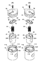
図10(A)は特許文献1(特開2000−2361号公報)に開示されたガス栓の部品構成を示す分解斜視図であり、図10(B)は図9のガス栓の部品構成を示す分解斜視図である。
図9及び図10(B)に示すガス栓101は、本体107を備えている。この本体107内には、ガス流路108が形成されている。図9において、本体107のガス流路108の左側がガス元管に繋がる入側部107Aであり、右側がガス機器に繋がる出側部107Bである。本体107内のガス流路108中には、テーパ円錐台面状の栓体摺動面108Xが形成されている。
The background art will be described with reference to FIGS. 9 and 10.
FIG. 9 is a cross-sectional view showing an example of a gas stopper with a pushing mechanism.
FIG. 10 (A) is an exploded perspective view showing the component configuration of the gas stopper disclosed in Patent Document 1 (Japanese Patent Laid-Open No. 2000-2361), and FIG. 10 (B) shows the component configuration of the gas stopper shown in FIG. It is a disassembled perspective view shown.
A
本体107内には、栓体109が回動可能に収められている。この栓体109の側面109aは、本体107内の栓体摺動面108Xに密に接している。栓体109内にエルボ状の連通孔109cが形成されている。この連通孔109cが本体107のガス流路108に合っているときはガスが流通し、連通孔109cがガス流路108から外れているときはガスが遮断される。栓体109の上部には、コイルバネ106を介して、ドライブシャフト115が配置されている。このドライブシャフト115の上部には、ツマミ103が皿小ネジ102で連結されている。
A
ドライブシャフト115は、コイルバネ106で図中上側に付勢されつつ、ツマミ103と栓体109とを回動不能且つ上下間隔可変に連結している。ツマミ103を人手で押し回すと、本体107内で栓体109が回動し、ガス栓101が開閉される。ドライブシャフト115の上側には肩部115a(図10(B)参照)が形成されており、外縁部にはストッパー113及びC型止め輪111が設けられている。ストッパー113は、ドライブシャフト115が図9中上側に位置するときに、ドライブシャフト115を回り止めする係止穴113a(図10(B)参照)を有している。C型止め輪111は、本体107の内溝107aに入り込んで、ストッパー113を上側から押さえるものである。
The
このような構成を有するガス栓101を開くには、人手でツマミ103を下側に押し、ドライブシャフト115をコイルバネ106の付勢力に抗して下側に移動させる。すると、ストッパー113の係止穴113aからドライブシャフト115が下に外れ、ツマミ103が回動可能状態となる。そして、人手でツマミ103を押したまま回すと、これと同時に栓体109も本体107内で回り、本体107のガス流路108と栓体109の連通孔109cとが合ってガスが流通する。一方、ガス栓101を閉じて人手を離すと、ドライブシャフト115がコイルバネ106の付勢力を受けて上側に移動し、その肩部115aがストッパ113の係止穴113aに入り込む。この時点で、ドライブシャフト115及び栓体109、ツマミ103が回動不能となる。
In order to open the
ところで、前述した図9及び図10(B)の押し回し機構付きのガス栓101は、基本的に8個の部品(皿小ネジ102、ツマミ103、コイルバネ106、本体107、栓体109、C型止め輪111、ストッパー113、ドライブシャフト115)から構成されているが、押し回し機構の不要なガス栓においては、できるだけ部品点数を減らしたい意向がある。そこで、本出願人は、特許文献1(特開2000−2361号公報)において、図10(A)に示すようなガス栓201を提案した。このガス栓201は、皿小ネジ202、ツマミ203、シール204、ロックピン205、コイルバネ206、本体207、栓体209の7部品を備えており、前述のガス栓101と比較すると、C型止め輪111、ストッパー113、ドライブシャフト115を有しない構成となっている。
By the way, the above-described
しかしながら、さらに組み立てが行い易く、製造コストの低いガス栓が求められている。
本発明は、このような課題を解決するためになされたものであって、組み立てが行い易く、製造コストの低いガス栓を提供することを目的とする。
However, there is a need for a gas stopper that is easier to assemble and has a lower manufacturing cost.
The present invention has been made to solve such a problem, and an object of the present invention is to provide a gas stopper that is easy to assemble and has a low manufacturing cost.
本発明のガス栓は、内部にガス流路及び栓体摺動面を有する本体と、 前記栓体摺動面で摺動し、前記ガス流路を開閉する栓体と、 該栓体を前記本体内に向けて付勢するバネと、 該バネを前記本体内に係止するストッパーと、 前記栓体を動かすツマミと、 該ツマミと前記ストッパーとを結合する結合部材と、を具備するガス栓であって、 前記ツマミが、前記本体の端部に回動可能に装着され、且つ、前記栓体とは相対回動不能に係合しており、 前記ツマミと前記本体との間に、前記栓体の回動範囲を制限する係合部が設けられていることを特徴とする。 The gas stopper of the present invention includes a main body having a gas flow path and a plug body sliding surface therein, a plug body that slides on the plug body sliding surface to open and close the gas flow path, and A gas stopper comprising: a spring that biases the body, a stopper that locks the spring in the main body, a knob that moves the stopper, and a coupling member that couples the knob and the stopper The knob is rotatably attached to an end of the main body, and is engaged with the plug body so as not to rotate relative to the main body. An engagement portion is provided to limit the rotation range of the plug body.
このガス栓は、本体、栓体、バネ、ストッパー、ツマミ、結合部材(ビス等)の6部品からなるので、従来のガス栓に比べ部品点数を少なくすることができる。このガス栓においては、ストッパーを本体に組み付けることでバネを押さえる構造であるので、従来のようにストッパー及びドライブシャフトを介してC型止め輪でバネを押さえる構造と比べて、ドライブシャフト及びC型止め輪の2部品の削減が実現されている。また、ガス栓を組み立てる際には、ストッパーを人手で押しながらバネを縮めて本体に組み付けることができるので、従来のようにストッパー及びドライブシャフトを挟んでC型止め輪を専用工具で押し付ける必要がなくなる。つまり、本ガス栓については、組み立ての際の専用工具が不要となり、組み立て作業が簡略化される。さらに、従来は、栓体の回動範囲の制限をドライブシャフトで行う構成であったため、ドライブシャフトの形状が複雑化して製造コストが嵩んでいた。本ガス栓では形状の複雑なドライブシャフトを削減し、栓体の回動範囲の制限はツマミと本体との間の係合部で行う構成となっているので、ガス栓の製造コストを低減し得る。 Since this gas plug is composed of six parts including a main body, a plug, a spring, a stopper, a knob, and a coupling member (such as a screw), the number of parts can be reduced as compared with a conventional gas plug. Since this gas stopper has a structure in which the spring is pressed by assembling the stopper to the main body, the drive shaft and the C type are compared with the conventional structure in which the spring is pressed by the C-type retaining ring via the stopper and the drive shaft. Reduction of two parts of the retaining ring is realized. Also, when assembling the gas stopper, the spring can be retracted and assembled to the main body while pushing the stopper manually, so it is necessary to press the C-type retaining ring with a dedicated tool across the stopper and drive shaft as in the past. Disappear. That is, the gas plug does not require a dedicated tool for assembling, and the assembling work is simplified. Furthermore, conventionally, since the drive shaft is limited in the rotation range of the plug, the shape of the drive shaft is complicated and the manufacturing cost increases. This gas stopper reduces the drive shaft with a complicated shape and limits the rotation range of the stopper at the engaging part between the knob and the main body. obtain.
本発明によれば、組み立てが行い易く、製造コストの低いガス栓を提供することができる。 According to the present invention, it is possible to provide a gas stopper that is easy to assemble and low in manufacturing cost.
以下、本発明の実施の形態について、図面を参照しながら詳細に説明する。
図1は、本発明の一実施例に係るガス栓の全体構成(閉栓時)を示す断面図である。
図2は、同ガス栓の分解図である。(A)は閉栓位置における平面図であり、(B)は閉栓位置における断面側面図である。
図3は、同ガス栓の全体構成(開栓時)を示す断面図である。
図4は、同ガス栓の分解図である。(A)は開栓位置における平面図であり、(B)は開栓位置における断面側面図である。
Hereinafter, embodiments of the present invention will be described in detail with reference to the drawings.
FIG. 1 is a cross-sectional view showing the entire configuration (when closed) of a gas stopper according to an embodiment of the present invention.
FIG. 2 is an exploded view of the gas stopper. (A) is a top view in a capping position, (B) is a cross-sectional side view in a capping position.
FIG. 3 is a cross-sectional view showing the entire configuration of the gas stopper (when opened).
FIG. 4 is an exploded view of the gas stopper. (A) is a top view in an opening position, (B) is a cross-sectional side view in an opening position.
図1〜図4には、本発明の一実施例に係るガス栓1の全体構造が示されている。図2及び図4にわかり易く示すように、このガス栓1は、本体10、栓体20、コイルバネ30、ストッパー40、ツマミ50、ネジ(結合部材)60の6部品からなる。なお、ネジ60に代えてリベット等を用いることもできる。
1 to 4 show the overall structure of a
本体10は真鍮製等であって、ツマミ50が取り付けられる上端部11、ガス元管に繋がる入側孔部12、ガス機器に繋がる出側孔部13を有している。本体10内部において、入側孔部12と出側孔部13との間はガス流路14となっており、このガス流路14中にはテーパ円錐台面状の栓体摺動面15が形成されている。さらに、栓体摺動面15の上側には、本体10の上端部11側に開放された内凹部17が形成されている。本体10の上端部11において、内凹部17の上端内縁には内周溝部19が形成されている。図2(A)及び図4(A)にわかり易く示すように、本体10の上端部11には、内周溝部19に繋がる一対のスリット部11Aが形成されているとともに、開度90°の円弧状に切り欠かれた切欠き段部11Bが形成されている。
なお、スリット部11A及び切欠き段部11Bの作用については後述する。
The
In addition, the effect | action of 11 A of slit parts and the
本体10の栓体摺動面15内部には、真鍮製等の栓体20が回動可能に収められている。この栓体20の外周面20aは、栓体摺動面15に密に接している。栓体20には、側面を貫通するガス流通孔21が形成されている。このガス流通孔21が本体10のガス流路14に合っているとき(図3及び図4参照)はガスが流通し、ガス流通孔21がガス流路14から外れているとき(図1及び図2参照)はガスが遮断される。図2にわかり易く示すように、栓体20の上端面には、一対の突起23が形成されている。これら両突起23の対向面間にはスペース23Aが存在し、このスペース23A中の栓軸芯部には円溝(円周面をなす凹部)25が形成されている。両突起23間の円溝25には、コイルバネ30が配置される。
A
図1及び図3に示すように、コイルバネ30の上端には、ステンレス鋼製等のストッパー40が配置されている。図2(A)及び図4(A)にわかり易く示すように、このストッパー40は帯状の部材である。ストッパー40の両端側面には、外側に張り出した張出片41がそれぞれ形成されている。図1及び図3に示す組み立て状態において、ストッパー40の各張出片41は本体10の内周溝部19内に配置される。このとき、ストッパー40はコイルバネ30の弾性力で本体10上端側に向けて付勢されるが、各張出片41が内周溝部19の上端面に当たることで抜け止めされる。ストッパー40の隅部(各張出片41を挟んで両側の端部)は、滑らかなアール状に形成されている。ストッパー40の中心には小円形のネジ係合孔43が形成されているとともに、このネジ係合孔43を挟んで両側には一対のほぼ枡形をしたツマミ係合孔45が形成されている。
なお、本体10とストッパー40との係合状態については後述する。
As shown in FIGS. 1 and 3, a
The engagement state between the
本体10の上端部11には、プラスチック製等のツマミ50が取り付けられている。このツマミ50の上面側中心には、上下に貫通するネジ孔51が掘り込まれている。ツマミ50の上面には、栓体20の開閉位置を識別するマーク50aが形成されている。一方、ツマミ50の下面側外周縁には円周溝53が掘り込まれており、この円周溝53内の一部には凸部54(後述する図7(A)参照)が形成されている。この凸部54が本体10の上端部11の切欠き段部11Bの両端面11B′11B″に当たることで、栓体20の回動範囲が制限される。さらに、ツマミ50の下面側において、ネジ孔51と円周溝53との間には、一対の係合突起55が形成されている。
A
図1及び図3に示す組み立て状態において、ツマミ50の円周溝53内には、本体10の上端部11が配置される。また、ツマミ50の各係合突起55は、ストッパー40の各ツマミ係合孔45を通って下側に突出し、栓体20の両突起23間のスペース23Aに係合する。これにより、ツマミ50と栓体20とがストッパー40を介して相対回動不能に連結される。そして、ツマミ50のネジ孔51内にネジ60が捩じ込まれることで、ツマミ50とストッパー40とが相対回動不能に結合される。
In the assembled state shown in FIGS. 1 and 3, the
次に、図5を参照しつつ、ガス栓1の組み立て手順(1)〜(6)について説明する。
図5(A)〜(F)は、本体にストッパーを組み付ける手順を説明するための平面図である。
(1)図5(A)に示すように、本体10内部に栓体20を入れる。このとき、本体10中心と両スリット部11Aとを結ぶ線C1と、栓体20のスペース23A幅方向中心線C2とが所定角度θ(60°程度)をなすようにする。
(2)図5(B)に示すように、栓体20の両突起23間の円溝25内にコイルバネ30を配置する。
Next, the assembly procedures (1) to (6) of the
5A to 5F are plan views for explaining a procedure for assembling the stopper to the main body.
(1) As shown in FIG. 5 (A), the
(2) As shown in FIG. 5B, a
(3)図5(C)に示すように、本体10の上端部11の各スリット部11Aにストッパー40の各張出片41を合わせ、ストッパー40と栓体20との間でコイルバネ30を縮めつつ、ストッパー40を本体10内に押し込む。
(4)図5(D)に示すように、本体10の内周溝部19に沿ってストッパー40を所定角度回す。このとき、栓体20のスペース23A上にストッパー40の両ツマミ係合孔45が位置するようにする。このとき、前述の通り、ストッパー40はコイルバネ30の弾性力で本体10上端側に向けて付勢されるが、各張出片41が内周溝部19の上端面に当たることで抜け止めされる。
これら(3)、(4)の手順からわかるように、本ガス栓1では、ストッパー40を人手で押しながらコイルバネ30を縮めて本体10に組み付けることができる。そのため、従来のようにストッパー及びドライブシャフトを挟んでC型止め輪を専用工具で押し付ける必要がなくなり、組み立て作業が簡略化される。
(3) As shown in FIG. 5C, the overhanging
(4) As shown in FIG. 5D, the
As can be seen from the procedures (3) and (4), in the
(5)図5(E)に示すように、本体10の上端部11にツマミ50を嵌め込む。これにより、ツマミ50の各係合突起55がストッパー40の各ツマミ係合孔45を通って栓体20の両突起23間のスペース23Aに係合し、ツマミ50と栓体20とがストッパー40を介して相対回動不能に連結される。このとき、ツマミ50の凸部54は、本体10の上端部11の切欠き段部11B内のほぼ中央(図5(E)中右端寄り)に位置することとなる。
(6)図5(F)に示すように、ツマミ50のネジ孔51内にネジ60を捩じ込む。このネジ60の下端がストッパー40のネジ係合孔43に係合することにより、ツマミ50とストッパー40とが相対回動不能に結合される。
(5) As shown in FIG. 5 (E), the
(6) As shown in FIG. 5F, the
次に、図6〜図8を参照しつつ、ガス栓1の本体10とストッパー40との組み付け状態、ならびに、ガス栓1の開閉時における本体10の切欠き段部11Bとツマミ50の凸部54との関係(回動範囲の規制)について説明する。
図6は、本発明に係るガス栓の本体とストッパーとの組み付け状態、ならびに、ガス栓開閉時における本体の切欠き段部とツマミの凸部との関係を示す平面図である。(A)は組み立て時の状態を示す図であり、(B)は閉栓時の状態を示す図であり、(C)は開栓時の状態を示す図である。
図7(A)は同ガス栓のツマミ下面側を示す斜視図であり、図7(B)はガス栓閉栓時の状態を示す斜視図であり、(C)はガス栓開栓時の状態を示す斜視図である。
図8(A)は同ガス栓閉栓時の状態を示す分解斜視図であり、(C)はガス栓開栓時の状態を示す分解斜視図である。
なお、図6においては、ツマミの凸部54及び両係合突起55のみが網目で図示されており、ツマミ全体は図示されていない。
Next, referring to FIGS. 6 to 8, the assembled state of the
FIG. 6 is a plan view showing the assembled state of the main body and stopper of the gas stopper according to the present invention and the relationship between the notch step portion of the main body and the convex part of the knob when the gas stopper is opened and closed. (A) is a figure which shows the state at the time of an assembly, (B) is a figure which shows the state at the time of closing, (C) is a figure which shows the state at the time of opening.
FIG. 7A is a perspective view showing the lower surface side of the knob of the gas stopper, FIG. 7B is a perspective view showing a state when the gas stopper is closed, and FIG. 7C is a state when the gas stopper is opened. FIG.
FIG. 8A is an exploded perspective view showing a state when the gas stopper is closed, and FIG. 8C is an exploded perspective view showing a state when the gas stopper is opened.
In FIG. 6, only the
図6(A)に示すガス栓1の組み立て時においては、図5(D)〜(F)を用いて前述したように、ストッパー40のツマミ係合孔45(及び本体10内の栓体20のスペース23A)にツマミ係合突起55(図7(A)参照)が係合しており、ツマミ凸部54(図7(A)参照)が本体上端部11の切欠き段部11B内のほぼ中央(図6(A)中右端寄り)に位置している。この図6(A)の状態からガス栓1を閉栓状態とするには、図6(B)に示すように、ツマミを矢印X方向に回す。すると、ツマミ50に係合しているストッパー40、栓体20も同時に矢印X方向に回る。このとき、図7(B)及び図8(A)にわかり易く示すように、ツマミ凸部54は、本体上端部11の切欠き段部11Bの円弧に沿って移動し、最終的に切欠き段部11Bの端面11B′に当たる。これにより、ツマミ50が本体10に対して回動不能となり、閉栓時の回動規制がなされる。
When assembling the
一方、この状態からガス栓1を開栓状態とするには、図6(C)に示すように、ツマミを矢印Y方向に回す。すると、ツマミ50に係合しているストッパー40、栓体20も同時に矢印Y方向に回る。このとき、図7(C)及び図8(B)にわかり易く示すように、ツマミ凸部54は、本体上端部11の切欠き段部11Bの円弧に沿って移動し、最終的に切欠き段部11Bの端面11B″に当たる。これにより、ツマミ50が本体10に対して回動不能となり、開栓時の回動規制がなされる。
このように、本ガス栓1では、栓体20の回動範囲を、ツマミ凸部54と本体10の切欠き段部11Bとにより制限することができる。
On the other hand, to bring the
As described above, in the
1 ガス栓
10 本体 19 内周溝部
11A スリット部 11B 切欠き段部11B
14 ガス流路 15 栓体摺動面
19 内周溝部
20 栓体 21 連通孔
30 コイルバネ
40 ストッパー 41 張出片
43 ネジ係合孔 45 ツマミ係合孔
50 ツマミ 54 凸部
55 係合突部
60 ネジ
DESCRIPTION OF
14
Claims (1)
前記栓体摺動面で摺動し、前記ガス流路を開閉する栓体と、
該栓体を前記本体内に向けて付勢するバネと、
該バネを前記本体内に係止するストッパーと、
前記栓体を動かすツマミと、
該ツマミと前記ストッパーとを結合する結合部材と、
を具備するガス栓であって、
前記ツマミが、前記本体の端部に回動可能に装着され、且つ、前記栓体とは相対回動不能に係合しており、
前記ツマミと前記本体との間に、前記栓体の回動範囲を制限する係合部が設けられていることを特徴とするガス栓。
A main body having a gas flow path and a plug sliding surface inside;
A plug that slides on the plug sliding surface and opens and closes the gas flow path;
A spring for biasing the plug body into the main body;
A stopper for locking the spring in the body;
A knob for moving the plug;
A coupling member for coupling the knob and the stopper;
A gas stopper comprising:
The knob is rotatably attached to the end of the main body, and is engaged with the plug body so as not to be relatively rotatable.
A gas stopper characterized in that an engaging portion is provided between the knob and the main body to limit a rotation range of the stopper.
Priority Applications (1)
| Application Number | Priority Date | Filing Date | Title |
|---|---|---|---|
| JP2004086463A JP2005273738A (en) | 2004-03-24 | 2004-03-24 | Gas cock |
Applications Claiming Priority (1)
| Application Number | Priority Date | Filing Date | Title |
|---|---|---|---|
| JP2004086463A JP2005273738A (en) | 2004-03-24 | 2004-03-24 | Gas cock |
Publications (2)
| Publication Number | Publication Date |
|---|---|
| JP2005273738A true JP2005273738A (en) | 2005-10-06 |
| JP2005273738A5 JP2005273738A5 (en) | 2007-02-22 |
Family
ID=35173649
Family Applications (1)
| Application Number | Title | Priority Date | Filing Date |
|---|---|---|---|
| JP2004086463A Pending JP2005273738A (en) | 2004-03-24 | 2004-03-24 | Gas cock |
Country Status (1)
| Country | Link |
|---|---|
| JP (1) | JP2005273738A (en) |
-
2004
- 2004-03-24 JP JP2004086463A patent/JP2005273738A/en active Pending
Similar Documents
| Publication | Publication Date | Title |
|---|---|---|
| TWI675979B (en) | Valves and integrated valves with locking mechanism | |
| DE602004002509D1 (en) | Valve | |
| US20070012308A1 (en) | Gas control knob that produces vibration and sound during rotation | |
| JP2005273738A (en) | Gas cock | |
| CN103090023B (en) | A kind of valve with radial type spool | |
| KR102241733B1 (en) | Angle valve with locking function | |
| JP3957306B2 (en) | Gas stopper | |
| JPH10169797A (en) | Gas plug | |
| JP2001050401A (en) | Valve device | |
| JP2009191985A (en) | Excess-flow check valve device for gas valve | |
| KR101676179B1 (en) | Water Tap | |
| KR200400995Y1 (en) | The gas safety dual valve. | |
| US11002379B2 (en) | Manual valve and pneumatic device | |
| JPH06265047A (en) | Safety device for gas cock | |
| JP3223135B2 (en) | Gas tap | |
| JP3863128B2 (en) | Gas stopper | |
| KR100956757B1 (en) | Swing Hinge Apparatus Of Swing-Type Portable Terminal | |
| KR200335052Y1 (en) | Device for Preventing the Movement of Binding Hole of Gas Container | |
| JP2009036228A (en) | Gas cock | |
| KR100527886B1 (en) | Device for Preventing the Movement of Binding Hole of Gas Container | |
| WO2022250046A1 (en) | Valve | |
| KR200215210Y1 (en) | Motion prevention device for ader of gas container | |
| JP2528556Y2 (en) | Gas cock | |
| JP3453346B2 (en) | Gas tap | |
| JPH116581A (en) | Lock device of duct opening and closing handle of fluid controller |
Legal Events
| Date | Code | Title | Description |
|---|---|---|---|
| A621 | Written request for application examination |
Effective date: 20061004 Free format text: JAPANESE INTERMEDIATE CODE: A621 |
|
| A521 | Written amendment |
Effective date: 20070109 Free format text: JAPANESE INTERMEDIATE CODE: A523 |
|
| A871 | Explanation of circumstances concerning accelerated examination |
Free format text: JAPANESE INTERMEDIATE CODE: A871 Effective date: 20070109 |
|
| A975 | Report on accelerated examination |
Effective date: 20070201 Free format text: JAPANESE INTERMEDIATE CODE: A971005 |
|
| A131 | Notification of reasons for refusal |
Free format text: JAPANESE INTERMEDIATE CODE: A131 Effective date: 20070206 |
|
| A02 | Decision of refusal |
Free format text: JAPANESE INTERMEDIATE CODE: A02 Effective date: 20070608 |