JP2005264635A - Segment member for regenerative pipe - Google Patents
Segment member for regenerative pipe Download PDFInfo
- Publication number
- JP2005264635A JP2005264635A JP2004081801A JP2004081801A JP2005264635A JP 2005264635 A JP2005264635 A JP 2005264635A JP 2004081801 A JP2004081801 A JP 2004081801A JP 2004081801 A JP2004081801 A JP 2004081801A JP 2005264635 A JP2005264635 A JP 2005264635A
- Authority
- JP
- Japan
- Prior art keywords
- lid
- opening
- pipe
- segment
- rehabilitation
- Prior art date
- Legal status (The legal status is an assumption and is not a legal conclusion. Google has not performed a legal analysis and makes no representation as to the accuracy of the status listed.)
- Pending
Links
- 230000001172 regenerating effect Effects 0.000 title abstract 4
- 230000002093 peripheral effect Effects 0.000 claims abstract description 21
- 239000003566 sealing material Substances 0.000 claims description 15
- 239000000945 filler Substances 0.000 claims description 14
- 238000003780 insertion Methods 0.000 description 17
- 230000037431 insertion Effects 0.000 description 17
- 238000000034 method Methods 0.000 description 13
- 230000003014 reinforcing effect Effects 0.000 description 12
- 210000000078 claw Anatomy 0.000 description 6
- 239000000463 material Substances 0.000 description 5
- 230000000694 effects Effects 0.000 description 3
- 229920003023 plastic Polymers 0.000 description 3
- 238000003466 welding Methods 0.000 description 3
- 239000004570 mortar (masonry) Substances 0.000 description 2
- 238000009418 renovation Methods 0.000 description 2
- 229920005989 resin Polymers 0.000 description 2
- 239000011347 resin Substances 0.000 description 2
- 238000007789 sealing Methods 0.000 description 2
- 239000010865 sewage Substances 0.000 description 2
- 125000006850 spacer group Chemical group 0.000 description 2
- 239000011083 cement mortar Substances 0.000 description 1
- 239000002131 composite material Substances 0.000 description 1
- 238000010276 construction Methods 0.000 description 1
- 239000003822 epoxy resin Substances 0.000 description 1
- 230000005484 gravity Effects 0.000 description 1
- 230000001771 impaired effect Effects 0.000 description 1
- 238000012423 maintenance Methods 0.000 description 1
- 230000013011 mating Effects 0.000 description 1
- 238000013008 moisture curing Methods 0.000 description 1
- 238000000465 moulding Methods 0.000 description 1
- 229920000647 polyepoxide Polymers 0.000 description 1
- 239000004645 polyester resin Substances 0.000 description 1
- 229920001225 polyester resin Polymers 0.000 description 1
- 239000004814 polyurethane Substances 0.000 description 1
- 229920002635 polyurethane Polymers 0.000 description 1
- 230000000717 retained effect Effects 0.000 description 1
- 239000000126 substance Substances 0.000 description 1
- XLYOFNOQVPJJNP-UHFFFAOYSA-N water Substances O XLYOFNOQVPJJNP-UHFFFAOYSA-N 0.000 description 1
Images
Classifications
-
- F—MECHANICAL ENGINEERING; LIGHTING; HEATING; WEAPONS; BLASTING
- F16—ENGINEERING ELEMENTS AND UNITS; GENERAL MEASURES FOR PRODUCING AND MAINTAINING EFFECTIVE FUNCTIONING OF MACHINES OR INSTALLATIONS; THERMAL INSULATION IN GENERAL
- F16L—PIPES; JOINTS OR FITTINGS FOR PIPES; SUPPORTS FOR PIPES, CABLES OR PROTECTIVE TUBING; MEANS FOR THERMAL INSULATION IN GENERAL
- F16L55/00—Devices or appurtenances for use in, or in connection with, pipes or pipe systems
- F16L55/16—Devices for covering leaks in pipes or hoses, e.g. hose-menders
- F16L55/162—Devices for covering leaks in pipes or hoses, e.g. hose-menders from inside the pipe
- F16L55/163—Devices for covering leaks in pipes or hoses, e.g. hose-menders from inside the pipe a ring, a band or a sleeve being pressed against the inner surface of the pipe
-
- F—MECHANICAL ENGINEERING; LIGHTING; HEATING; WEAPONS; BLASTING
- F16—ENGINEERING ELEMENTS AND UNITS; GENERAL MEASURES FOR PRODUCING AND MAINTAINING EFFECTIVE FUNCTIONING OF MACHINES OR INSTALLATIONS; THERMAL INSULATION IN GENERAL
- F16L—PIPES; JOINTS OR FITTINGS FOR PIPES; SUPPORTS FOR PIPES, CABLES OR PROTECTIVE TUBING; MEANS FOR THERMAL INSULATION IN GENERAL
- F16L55/00—Devices or appurtenances for use in, or in connection with, pipes or pipe systems
- F16L55/16—Devices for covering leaks in pipes or hoses, e.g. hose-menders
- F16L55/162—Devices for covering leaks in pipes or hoses, e.g. hose-menders from inside the pipe
-
- F—MECHANICAL ENGINEERING; LIGHTING; HEATING; WEAPONS; BLASTING
- F16—ENGINEERING ELEMENTS AND UNITS; GENERAL MEASURES FOR PRODUCING AND MAINTAINING EFFECTIVE FUNCTIONING OF MACHINES OR INSTALLATIONS; THERMAL INSULATION IN GENERAL
- F16L—PIPES; JOINTS OR FITTINGS FOR PIPES; SUPPORTS FOR PIPES, CABLES OR PROTECTIVE TUBING; MEANS FOR THERMAL INSULATION IN GENERAL
- F16L55/00—Devices or appurtenances for use in, or in connection with, pipes or pipe systems
- F16L55/18—Appliances for use in repairing pipes
Landscapes
- Engineering & Computer Science (AREA)
- General Engineering & Computer Science (AREA)
- Mechanical Engineering (AREA)
- Pipe Accessories (AREA)
- Lining And Supports For Tunnels (AREA)
- Lining Or Joining Of Plastics Or The Like (AREA)
- Rigid Pipes And Flexible Pipes (AREA)
- Sewage (AREA)
Abstract
Description
本発明は、下水管などの既設管を更生するために既設管内で組み立てられる更生管を構成する更生管用セグメント部材に関するものである。 The present invention relates to a rehabilitating pipe segment member constituting a rehabilitating pipe assembled in an existing pipe in order to rehabilitate an existing pipe such as a sewage pipe.
下水管などの既設管を更生するために、既設管内で外径が既設管の内径より少し小さな更生管を組み立て、この更生管の外周と既設管の内壁面との隙間に充填材を充填し硬化させて複合管を構築する既設管の更生方法が下記の特許文献1などにより知られている。更生管が円管で径が1000〜1800mm程度までの場合、更生管の組み立ては図20に示すように行われ、組み立てを行う作業者Sが既設管に連通するマンホール内で、更生管3を構成するセグメント部材1を更生管3の周方向に相当する方向に複数連結して短いリング状の管ユニット2を組み立てた後、この管ユニット2を既設管内に搬入し、順次長さ方向に連結して更生管3を組み立てる(以下「リング組み立て」という)。また、図21に示すように更生管3が径2000mm程度以上の大口径のもの、あるいは図22に示すように更生管3が矩形管などである場合は、リング組み立てが困難であるため、作業者Sが既設管内でセグメント部材1を単体で順次1つづつ更生管3の長さ方向と周方向に連結して更生管3を組み立てている(以下「単体組み立て」という)。
In order to rehabilitate existing pipes such as sewage pipes, a rehabilitation pipe whose outer diameter is slightly smaller than the inner diameter of the existing pipe is assembled in the existing pipe, and a filler is filled in the gap between the outer periphery of this rehabilitation pipe and the inner wall of the existing pipe. A method of rehabilitating an existing pipe that is cured to construct a composite pipe is known from
セグメント部材1は更生管3の内周面を構成する内面板を有し、この内面板には、セグメント部材1どうしをボルトとナットで更生管3の周方向に相当する方向に連結する作業を行うための長方形の開口部が長さ方向の両端部に形成されている(図4の開口部101a参照)。この開口部は、既設管更生工事でセグメント部材どうしの周方向の連結が終了した後に蓋を固定して塞がれる。蓋の固定方法として、従来では、
(1)蓋に形成した爪を係合させる方法
(2)蓋を溝にスライドさせて嵌合する方法
(3)超音波溶着する方法
が採用されている。
The
(1) A method of engaging the claw formed on the lid, (2) a method of sliding the lid into the groove and fitting it, and (3) a method of ultrasonic welding.
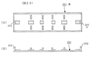
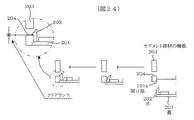
(1)の方法では、図23(A),(B)に示すように長さ方向の両端部に爪202が形成された長方形の蓋201の周縁の側面に不図示のシール材を塗布した後、図24に示すように、蓋201をセグメント部材の内面板の開口部101aに嵌め込みながら爪202のそれぞれを弾性変形させて開口部101aの両端に面するセグメント部材の側板203に形成された係合孔204のそれぞれに係合させることにより、蓋201を固定する。
In the method (1), as shown in FIGS. 23A and 23B, a sealing material (not shown) is applied to the side surface of the peripheral edge of the
(2)の方法では、開口部の長さ方向に沿った両側縁に溝、蓋の長さ方向に沿った両側縁に凸部がそれぞれの長さ方向に沿って形成され、蓋の周縁の側面にシール材を塗布した後、蓋の凸部を開口部の溝に挿入して蓋を長さ方向に奥までスライドさせて嵌合させることにより蓋を固定する。 In the method (2), grooves are formed on both side edges along the length direction of the opening, and convex portions are formed on both side edges along the length direction of the lid along each length direction. After the sealing material is applied to the side surface, the convex portion of the lid is inserted into the groove of the opening, and the lid is slid in the length direction to the back to fit the lid.
(3)の方法では、蓋を開口部に嵌め込んだ後、蓋の周縁部と開口部の周縁部を超音波溶着して蓋を固定する。
上記(1)の固定方法では、蓋201の爪202を弾性変形させて係合させるため、図24の左上側に係合部分を拡大して示すように、爪202と係合孔204の係合面との間にクリアランスが必要である。このクリアランスがないと、爪202が係合孔204の係合面にうまく係合できず、係合が外れ易くなってしまう。
In the fixing method (1) above, the
しかしながら、上記クリアランスがあると、更生管の組み立て後、更生管の外周と既設管の内壁面との隙間に充填材を充填する際に、蓋201に対して充填材からの圧力が図24中で下方向へ加わることにより、蓋201が上記クリアランスの分だけ下方向に変位して蓋201の周縁の側面と開口部の周縁の内側面との間に隙間ができ、開口部の部分における水密性を保持できなくなる場合がある。
However, when the clearance is present, after the rehabilitation pipe is assembled, when the filler is filled in the gap between the outer periphery of the rehabilitation pipe and the inner wall surface of the existing pipe, the pressure from the filling material is applied to the
また、(2)の固定方法では、蓋の凸部を開口部の溝に嵌合させて蓋を長さ方向に奥までスライドさせる際に、蓋の両側縁に塗布されたシール材がスライドによって剥がれてしまい、シール効果が著しく損なわれてしまう場合がある。また、凸部と溝の間に嵌合のためのクリアランスが必要なこともあり、開口部の部分における水密性の保持が悪くなってしまう。 In the fixing method (2), when the convex portion of the lid is fitted in the groove of the opening and the lid is slid in the length direction, the sealing material applied to both side edges of the lid is slid. It may peel off and the sealing effect may be remarkably impaired. Moreover, the clearance for a fitting may be needed between a convex part and a groove | channel, and the maintenance of watertightness in the part of an opening part will worsen.
また、(3)の超音波溶着による固定方法では、図20のようなリング組み立てを行なう場合にのみ有効であり、図21ないし図22のような単体組み立てには適用できないという問題があった。 Further, the fixing method by ultrasonic welding (3) is effective only when the ring assembly as shown in FIG. 20 is performed, and there is a problem that it cannot be applied to the single assembly as shown in FIGS.
本発明の課題は、以上のような問題を解決し、更生管用セグメント部材において、セグメント部材どうしを更生管の周方向に相当する方向に連結する作業を行うための開口部に蓋を固定する構造であって、蓋を固定して塞いだ開口部の部分における水密性を充分に確保することができるとともに、更生管をリング組み立てする場合でも単体組み立てする場合でも適用することができる固定構造を提供することにある。 An object of the present invention is to solve the above-described problems, and in a rehabilitating pipe segment member, a structure in which a lid is fixed to an opening for connecting the segment members in a direction corresponding to the circumferential direction of the rehabilitating pipe In addition, it is possible to secure a sufficient water-tightness in the opening portion that is closed by fixing the lid, and to provide a fixing structure that can be applied even when the rehabilitation pipe is assembled in a ring or in a single assembly. There is to do.
上記の課題を解決するため本発明は、
既設管を更生するための更生管用セグメント部材であって、
前記セグメント部材どうしを該更生管の周方向に連結する作業を行なうための開口部を内面に形成した内面板と、
突起と第1と第2の回動位置間を回動する係合部材を設けた蓋とを有し、
前記蓋を内面板の下面側から開口部に嵌め込み、突起を開口部の一方の側縁部に係合させるとともに、係合部材を第1の回動位置から第2の回動位置に回動させて開口部の前記側縁部と反対側の他方の側縁部に係合させることにより、前記蓋が開口部に固定されて開口部が塞がれるようにしたことを特徴とする。
In order to solve the above problems, the present invention
A segment member for rehabilitation pipes for rehabilitating existing pipes,
An inner plate formed on the inner surface with an opening for connecting the segment members in the circumferential direction of the rehabilitation pipe;
A protrusion and a lid provided with an engaging member that rotates between the first and second rotation positions;
The lid is fitted into the opening from the lower surface side of the inner surface plate, the protrusion is engaged with one side edge of the opening, and the engaging member is rotated from the first rotation position to the second rotation position. The lid is fixed to the opening so that the opening is closed by engaging with the other side edge of the opening opposite to the side edge.
本発明による更生管用セグメント部材の蓋の固定構造によれば、蓋の周縁の側面にシール材を塗布して蓋を固定する場合にシール材が剥がれることがなく、蓋を固定した状態で充填材からの圧力がかかっても開口部と蓋の周縁の側面間にクリアランスが生じることがないので、蓋を固定した開口部の部分における水密性を充分に確保することができるとともに、更生管をリング組み立てする場合でも単体組み立てする場合でも適用することができるという優れた効果が得られる。 According to the lid fixing structure of the segment member for rehabilitation pipe according to the present invention, when the sealing material is applied to the side surface of the peripheral edge of the lid and the lid is fixed, the sealing material is not peeled off, and the filling material is fixed in the state where the lid is fixed. Since there is no clearance between the opening and the side of the peripheral edge of the lid even when pressure is applied from the side, it is possible to ensure sufficient water-tightness at the portion of the opening to which the lid is fixed, and the rehabilitation pipe is ringed The excellent effect that it can be applied to the case of assembling or the case of assembling alone is obtained.
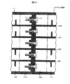
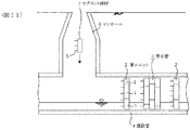
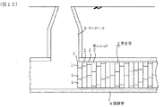
以下、図を参照して本発明の実施の形態を説明する。実施例の更生管用セグメント部材(以下、単にセグメント部材という)は、下水管などの既設管を更生するために、図11及び図12に示すように、既設管4内で短い円形リング状の管ユニット2からリング組み立てされる更生管3を構成するセグメント部材1であり、管ユニット2を周方向に複数等分、例えば5等分したものに相当する。このセグメント部材1を更生管3の周方向に複数連結して管ユニット2が組み立てられ、これを順次更生管3の管長方向に連結して更生管3が組み立てられる。なお、実施例では更生管をリング組み立てするものとしたが、単体組み立てするものとしてもよい。また、実施例では更生管を円管としたが、矩形管など管長方向に直交する断面形状が円形以外の形状である場合、及び更生管が文字通り管として断面形状が閉じた形状ではなく、例えば馬蹄形や半円形など片側が開いた形状である場合のそれぞれに用いられるセグメント部材にも本発明の構造を適用できることは勿論である。
Embodiments of the present invention will be described below with reference to the drawings. The segment member for rehabilitating pipe (hereinafter simply referred to as segment member) of the embodiment is a short circular ring-shaped tube in the existing
図1〜図4は、実施例のセグメント部材1の構造を説明するもので、図1はセグメント部材1の全体の上面、図2は図1中の矢印C方向に見た側面、図3は図1中のA−A線に沿った断面、図4はセグメント部材1の下面を示している。
1 to 4 illustrate the structure of the
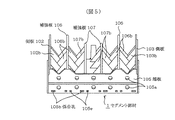
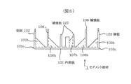
セグメント部材1は、所定角度分、例えば72度分の円弧状に湾曲して下面(前記円弧の内側面)が管ユニット2の内周面を構成する内面板101と、その上面(円弧の外側面)において、円弧の周方向に沿った両側縁に沿って外方に向かって立設された側板102,103と、円弧の両端縁に沿って外方に向かって立設された端板104,105と、これらの内側において円弧の周方向に沿って2枚ずつ外方に向かって立設された背の高い外側の補強板106及び背の低い内側の補強板107とを透明なプラスチックで一体成形したものとして構成されている。
The
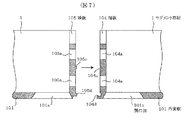
更生管3の周方向に相当する内面板101の円弧の周方向の両端部のそれぞれには、長方形の開口部101aが端板104,105の下端縁に沿って内面板101の幅より僅かに短い長さで形成されている。開口部101aの四方の周縁の内側面は、内面板101の上面(外側面)側から下面(内側面)側に向かって広がるように傾斜している(図7参照)。この開口部101aは、セグメント部材1どうしを管ユニット2の周方向、すなわち更生管3の周方向に相当する方向に連結するためのボルト6(図8及び図9参照)の締め付け作業を内側から行うためのものである。その締め付け作業後に、開口部101aを塞ぐ後述する蓋14(図14参照)が開口部101aに固定される。
A
側板102,103には、それぞれボルト挿通孔102a,103aが上記円弧の周方向に所定間隔で複数(ここでは14個)形成されている。その径は、図10に示す管ユニット2どうしを連結するためのボルト9の頭ないしナット10の径より僅かに大きくなっている。
The
端板104,105には、セグメント部材1どうしを上記周方向に相当する方向に連結するためのボルト6(図8及び図9参照)を挿通するボルト挿通孔104a,105aが補強板106,107により幅方向に5つに区分された部分のそれぞれの中央部の上下に2つずつ形成されている。また、図5(図1の矢印D方向の矢視図)に示すように、端板105において内面板101の上面に連続する下端部には複数の係合孔105bが開口部101aの長さ方向に沿った側縁に沿って複数箇所に形成されている。これは後述する蓋14の複数の突起14a(図14参照)のそれぞれを係合させるためのものであり、端板104にも同様に複数の係合孔104b(図18参照)が形成されている。また、端板105の下端部にはエア抜き孔105eが複数箇所に形成され、端板104にも同様に不図示のエア抜き孔が形成されている。また、図7に示すように、端板104の外側面にはV字形の溝104cと、上側が溝で下側が凸部になった嵌合部104dが上下方向の中央部と下端部のそれぞれで幅方向に延びて形成されている。また、端板105の外側面には溝104cと嵌合部104dのそれぞれと逆の形状の凸部105cと嵌合部105dが対応する位置に形成されている。
The
補強板106,107はセグメント部材1全体の機械的強度を補強するものであり、それぞれに管ユニット2を連結するためのボルト9(図10参照)を挿通するための複数のボルト挿通孔106aと切り欠き部107aが側板102,103のボルト挿通孔102a,103aのそれぞれに対応する位置に形成されている。ボルト挿通孔106aの径は、ボルト9の軸部分の径よりごく僅か大きいが、ボルト9の頭ないしナット10の径より小さくなっている。
The reinforcing
また、側板102,103の内側面と補強板106,107の両側面(補強板107の一方は片側面のみ)には、それぞれの変形を防ぐために側方に張り出した複数の小さな凸板102b,103b,106b,107bが隣り合うボルト挿通孔102a,103a,106a及び切り欠き部107aの間の位置のそれぞれに互い違いになるように形成されている。これらは、図5及び図6(図1中のB−B線に沿った断面図)に示すように、直角三角形に形成され、その底辺が内面板101に連続している。
In addition, a plurality of small
また、図6に示すように、側板102の外側面の下端部には上側が溝で下側が凸部とされた嵌合部102c、側板103の外側面の下端部には嵌合部102cと逆の形状の嵌合部103cが内面板101の側縁に沿ってその全長に渡って形成されている。
In addition, as shown in FIG. 6, the lower end portion of the outer side surface of the
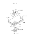
次に、内面板101の開口部101aを塞ぐ蓋の構造を図14〜図16により説明する。
Next, the structure of the lid that closes the
図14の(A)は蓋14の上面(セグメント部材1の円弧の外側面に対応した面)、(B)は長さ方向に沿った側面、(C)は幅方向に沿った側面を示している。蓋14は、セグメント部材1の本体と同様に透明なプラスチックからなり、開口部101aに対応する形状と大きさの長方形の板状に形成されており、その四方の周縁の側面は、開口部101aの周縁の内側面の傾斜に対応して、上面側から下面側に向かって広がるように傾斜し、さらにその傾斜した周縁の側面の上側寄りの部分が「く」の字形の凹部14cとして凹んでいる。
14A shows the upper surface of the lid 14 (the surface corresponding to the outer surface of the arc of the segment member 1), FIG. 14B shows the side surface along the length direction, and FIG. 14C shows the side surface along the width direction. ing. The
蓋14の上面には、複数個、例えば4つの突起14aが上面の長さ方向に沿った一方の側縁上の4箇所に設けられており、それぞれの先端部が前記の側縁から上面に平行に張り出している。また、先端部がL字形に屈曲した突起としてのアンカー14b(図15参照)が蓋14の上面で突起14a側と反対側の側縁の近傍の2箇所に形成されている。
On the upper surface of the
また、蓋14の上面には、複数個、例えば3つの係合部材15が突起14a側と反対側の側縁に沿って並ぶように配置され、それぞれ回動軸16により、蓋14の上面に平行に回動可能に軸支されている。ただし、係合部材15は、後述の構造で蓋14の上面に弾性的に圧接するので、ある程度以上の力を加えないと回動できないようになっている。
Further, a plurality of, for example, three engaging
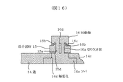
係合部材15と回動軸16は蓋14の本体と同様に透明なプラスチックから形成されている。図15に示すように、係合部材15は、中央に溝15aが形成されて「U」字形に形成されており、その上面には2本の細い凸部15bが溝15aの両側縁に沿って形成されている。凸部15bの断面形状は直角三角形に近い台形になっている(図16参照)。また、溝15aの奥の面には、細い凸部15cが縦方向に延びて形成されている。また、係合部材15の先端部と後端部のそれぞれの下面には、少しだけ突出した凸部15d,15eが形成されている。
The engaging
また、回動軸16は、中間部が切り欠き部16aとして断面形状がほぼ四角柱状に切り欠かれており、下端部には径が他の部分より大きなツバ16eが形成されている。切り欠き部16aの図16中で左右の天井部の内側には溝16bが係合部材15の凸部15bに対応した断面形状に形成されており、その外側に舌部16cが下向きの円弧形状に形成されている。また、切り欠き部16aの図15中で図示されない右側の背面には、図16中に破線で示す縦溝16dが形成され、ツバ16eの下面(回動軸16の下端面)には小さな孔(凹部)16fが2つ形成されている。
Further, the
また、蓋14には、回動軸16を回動可能に嵌合して軸受けする軸受孔14dが3箇所に貫通して形成されている。軸受孔14dは段差を有し、下部の径が回動軸16のツバ16eの径に対応し、上部の径が回動軸16のツバ16eより上の部分の径に対応している。
The
回動軸16は軸受孔14dに対して下側から挿入され、ツバ16eが軸受孔14dの下部、ツバ16eの上から切り欠き部16aの下までの部分が軸受孔14dの上部に嵌合された状態で、切り欠き部16aから上の部分が蓋14bの上面の上に突出する。この状態で、切り欠き部16aの部分に対して係合部材15を側方から挿入して嵌合させることにより、係合部材15が蓋14の上面に取り付けられる。
The rotating
ここで、係合部材15の高さ(凸部15dないし15eを含めた厚さ)の寸法が切り欠き部16aの下面から舌部16cの下端までの寸法より僅かに大きいことにより、係合部材15は上面で舌部16cを僅かに上側に撓ませながら切り欠き部16aに対して圧入して嵌合される。この場合、図16に示すように、係合部材15の溝15aの左右の部分が切り欠き部16aの左右の部分に入り、凸部15bのそれぞれが溝16bのそれぞれに入り、凸部15cが縦溝16dに入って嵌合するまで圧入される。こうして係合部材15を切り欠き部16aに圧入して嵌合させることにより、係合部材15が回動軸16と一体的に回動可能に取り付けられ、また、係合部材15により回動軸16が抜け止めされる。
Here, since the dimension of the height of the engaging member 15 (thickness including the
なお、この状態で、回動軸16の舌部16cの部分が係合部材15を弾性的に押圧することにより、係合部材15の凸部15d,15eの下面が蓋14の上面に弾性的に圧接するので、係合部材15に上下方向のガタは生じない。
In this state, the
このように係合部材15が取り付けられた状態で、回動軸16の孔16fのそれぞれに不図示の工具の凸部を係合させ、工具によって回動軸16を蓋14の下面側から回動させることにより、係合部材15を回動させることができる。ここで、蓋14の上面には、突起としてのストッパー14eが軸受孔14dのそれぞれの近傍に2つづつ形成されており、このストッパー14eに係合部材15が当接することにより、係合部材15の回動範囲が図14(A)に示す回動位置(以下、初期位置という)から図19に示す回動位置(以下、係合位置という)までの90度の範囲に制限される。図14(A)の初期位置では、係合部材15は、その「U」字形の向きが蓋14の長さ方向と平行になり、全体が蓋14の上面上にある(上面の側縁の内側にある)。図19の係合位置では、係合部材15は、その「U」字形の向きが蓋14の長さ方向に対して垂直になり、先端部が蓋14の上面の突起14a側の側縁と反対側の側縁から外側に張り出すようになっている。
With the engaging
次に、セグメント部材1を用いる既設管更生工事について説明する。その工事では、まず図11に示す既設管4に連通するマンホール5にセグメント部材1を搬入するが、その前に図10に示すように管ユニット2の連結用のボルト9をセグメント部材1に固定しておく。
Next, the existing pipe renovation work using the
ボルト9を固定するには、まずボルト9をセグメント部材1の側板102,103の一方、例えば側板102のボルト挿通孔102aから挿入して、補強板106,107のボルト挿通孔106a及び切り欠き部107aと側板103のボルト挿通孔103aに挿通させ、ボルト9の頭が側板102側の補強板106に当接する位置まで挿入する。そして側板103から外側に突出するボルト9の先端部にナット10を螺合させ、側板102側の補強板106に当接する位置に締め付け、さらに破線で示した円筒状の位置決め部材19をボルト9の先端側から挿通させて側板103側の補強板106に当接する位置まで挿入することにより、ボルト9が固定される。位置決め部材19はボルト9をボルト挿通孔103aと同心に位置決めするとともに、後述のように連結される管ユニット2どうしのボルト挿通孔102a,103aの位置を合わせるためのものである。
In order to fix the
なお、ボルト9の固定本数はボルト挿通孔102aなどの数の半数以下とし、ボルト挿通孔の1個ないし複数個置きに固定する。また、固定されたボルト9の側板103から突出する部分の長さがセグメント部材1の幅(側板102の外側面から側板103の外側面まで)より僅かに小さくなるようにボルト9の長さが設定されている。
The number of
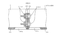
このようにしてボルト9を固定した複数のセグメント部材1を、図7〜図9に示すようにして周方向に連結する。すなわち、まず図7中で左側のセグメント部材1の端板105の凸部105cと嵌合部105dを右側のセグメント部材1の端板104の溝104cと嵌合部104dに嵌合させて端板104,105どうしを密着させる。次に、図8,図9に示すボルト6を右側のセグメント部材1の内面板101の開口部101aから入れて端板104,105のボルト挿通口104a,105aに挿通し、左側のセグメント部材1の開口部101aからナット7を入れてボルト6に螺合させ、端板105に締め付けることにより、セグメント部材1,1どうしが連結される。
The plurality of
このようにして複数のセグメント部材1を順次周方向に連結して図11に示す管ユニット2を組み立てる。その際に、周方向に連結したセグメント部材1の内面板101の開口部101aに図14の蓋14を嵌合して固定する。
In this way, the plurality of
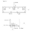
その場合、まず蓋14の係合部材15のそれぞれを先述した図14(A)の初期位置に回動させておき、図17(A),(B),(C)に斜線を付して示すように蓋14の周縁の側面にシール材17を塗布する。シール材17は施工性と耐薬品性を備えたもので、例えば一液性ポリウレタン系湿気硬化型のものとする。
In that case, each of the engaging
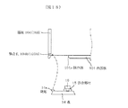
次に、図18に破線の矢印で示すように蓋14を内面板101の下面側から開口部101aに嵌め込み、突起14aのそれぞれをセグメント部材1の端板104(ないし105)の係合孔104b(ないし105b)に挿入し係合させる。係合孔104b(ないし105b)の下面は、内面板101の上面であって、開口部101aの端板104(ないし105)側の側縁部の上面であり、これに突起14aが係合することになる。
Next, as shown by broken line arrows in FIG. 18, the
そして蓋14を押圧して蓋14の周縁の側面を開口部101aの周縁の側面に圧着させた状態で、蓋14の下面に露出する回動軸16のツバ16eの下面の孔16fに不図示の工具を係合させて、回動軸16を回動させることにより、図19(A),(B)に示すように係合部材15のそれぞれを先述した係合位置まで90度回動させる。これにより、係合部材15のそれぞれの先端部が蓋14の上面の側縁から外側に張り出し、凸部15dが内面板101の上面で開口部101aの端板104(ないし105)側と反対側の側縁部の上面に弾性的に圧接して係合し、蓋14が開口部101aに固定される。
Then, the
管ユニット2を組み立てたら、順次、管ユニット2を既設管4内の更生管3の組立位置まで搬入し、順次長さ方向に連結して更生管3を組み立てる。
When the
図10は、管ユニット2どうしをボルト9により連結する様子を示しており、左側の管ユニット2を右側の更生管3に組み付けられている管ユニット2に連結するには、まず右側の管ユニット2のセグメント部材1の側板103から突出しているボルト9を左側の管ユニット2のセグメント部材1のボルト9が固定されていない部分の側板102と補強板106,107のボルト挿通孔102a,106a及び切り欠き部107aに挿通させ、位置決め部材19をボルト挿通孔102aに挿入させるようにして、左側の管ユニット2のセグメント部材1の側板102を右側の管ユニット2のセグメント部材1の側板103に押し付け、図6に示した嵌合部102cを嵌合部103cに嵌合させて側板102,103を密着させる。ここで、右側の管ユニット2のセグメント部材1から突出したボルト9の先端部は左側の管ユニット2のセグメント部材1の側板103の内側近傍に達するので、ボルト挿通孔103aからナット10をボルト9の先端部に螺合させて側板103の隣りの補強板106に締め付けることにより、左側の管ユニット2が右側の管ユニット2に固定され、連結される。このようにして、図11から図12に示した様に、管ユニット2を順次連結して更生管3を組み立て、その長さを延ばしてゆく。
FIG. 10 shows a state in which the
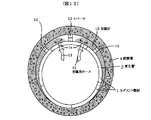
ところで、組み立てた更生管3は、後述する充填材より比重が小さく、充填材に浮くので、これを下方に押えて既設管4と同心の位置から少し下方にずれた位置で、その外周の下端が既設管4の管底に接する位置に位置調整する必要がある。このため、管ユニット2を複数個連結して更生管3を所定長さ(例えば1m位)組み立てる毎に、図13に示すスペーサ13を更生管3の上側外周の複数箇所においてその外周と既設管4の内壁面との間に挿入して位置調整する。
By the way, the assembled rehabilitating
更生管3の全長の組立と位置調整が終了したら、下記の充填材の充填時に更生管3の変形を防ぐための不図示の支柱を更生管3内に数m位の間隔で上下に垂直、及び左右に水平に設置する。その後、図13に示すように、充填材12を既設管4の内壁面と更生管3の外周との隙間のスペース及び更生管3を構成するセグメント部材1の内面板101の外側のスペースに充填する。充填材12は、セメントモルタル、あるいはエポキシ樹脂やポリエステル樹脂などを主材とするレジンモルタルなどからなる。その充填は、更生管3の長さの数m毎に、これを構成する上側のセグメント部材1の適当な位置に孔1aを形成して、これに充填用ホース11を接続し、このホース11から充填材12を注入して行う。なお、この充填の前に、組み立てた更生管3の全長の両端の外周と既設管4の内壁面との隙間を不図示のレジンパテやモルタルからなるシール材で塞いでおく。
When the assembly and the position adjustment of the full length of the
充填材12の充填が終了した後、充填材12が凝結して硬化したら、孔1aをシール材で塞ぎ、不図示の支柱を撤去するなどして既設管更生工事が完了する。なお、硬化する充填材12中に蓋14のアンカー14bのそれぞれが食い込んでいることにより、蓋14の開口部101aに対する固定が補強される。
After the filling of the filler material 12 is completed, when the filler material 12 is condensed and hardened, the existing pipe rehabilitation work is completed by closing the hole 1a with a sealing material and removing a column (not shown). In addition, the anchor 14b of the
以上のような実施例によれば、蓋14の開口部101aに対する固定は、図17〜図19で先述したようにして簡単に行なうことができる。図17のように蓋14の周縁の側面にシール材17を塗布し、図18のように蓋14を開口部101aに嵌め込んで圧着するときには、従来例のように蓋をスライドさせずにそのまま嵌め込むので、シール材を剥がしてしまうことがない。また、蓋14の周縁の側面に形成された凹部14cにシール材17が溜まるので、シール材を充分な量だけ塗布することができ、これが圧着で伸びて充分にシールを行うことができる。
According to the embodiment as described above, the
また、突起14aを係合孔104bないし105bに挿入して開口部101aの側縁部の上面に係合させるときに、蓋14がフリーな状態であるので、突起14aと係合孔104b,105bのクリアランスを殆どゼロにしても突起14aを支障なく係合させることができる。
Further, when the projection 14a is inserted into the engagement holes 104b to 105b and engaged with the upper surface of the side edge portion of the
また、図19のように、係合部材15のそれぞれを係合位置まで回動させて蓋14を開口部101aに固定するときに、係合部材15の先端部の凸部15dが開口部101aの長さ方向に沿った一方の側縁部の上面に弾性的に圧接して係合するため、蓋14の周縁の側面が開口部101aの周縁の側面に弾性的に押し付けられるので、両者の側面間にクリアランスは生じない。
Further, as shown in FIG. 19, when each of the engaging
従って、充填材からの圧力がかかっても、蓋14の周縁の側面と開口部101aの周縁の側面との間にクリアランスが生じないとともに、上述のようにシール効果も充分に得られるので、蓋14を固定して塞いだ開口部101aの部分における水密性を充分に確保することができる。また、以上では更生管3をリング組み立てするものとしたが、本実施例の蓋14の固定構造は、蓋14をセグメント部材1の下面側(その円弧の内側面側)から固定できるので、更生管を単体組み立てする場合にも適用できることは勿論である。
Therefore, even if pressure is applied from the filler, there is no clearance between the peripheral side surface of the
1 セグメント部材
2 管ユニット
3 更生管
4 既設管
5 マンホール
6 セグメント部材連結用のボルト
7 セグメント部材連結用のナット
9 管ユニット連結用のボルト
10 管ユニット連結用のナット
11 充填用ホース
12 充填材
13 スペーサ
14 蓋
14a 突起
14b アンカー
14e ストッパー
15 係合部材
15a 溝
15b〜15e 凸部
16 回動軸
16a 切り欠き部
16c 舌部
DESCRIPTION OF
Claims (10)
前記セグメント部材どうしを該更生管の周方向に連結する作業を行なうための開口部を内面に形成した内面板と、
突起と第1と第2の回動位置間を回動する係合部材を設けた蓋とを有し、
前記蓋を内面板の下面側から開口部に嵌め込み、突起を開口部の一方の側縁部に係合させるとともに、係合部材を第1の回動位置から第2の回動位置に回動させて開口部の前記側縁部と反対側の他方の側縁部に係合させることにより、前記蓋が開口部に固定されて開口部が塞がれるようにしたことを特徴とする更生管用セグメント部材。 A segment member for rehabilitation pipes for rehabilitating existing pipes,
An inner plate formed on the inner surface with an opening for connecting the segment members in the circumferential direction of the rehabilitation pipe;
A protrusion and a lid provided with an engaging member that rotates between the first and second rotation positions;
The lid is fitted into the opening from the lower surface side of the inner surface plate, the protrusion is engaged with one side edge of the opening, and the engaging member is rotated from the first rotation position to the second rotation position. The lid is fixed to the opening so that the opening is closed by engaging with the other side edge opposite to the side edge of the opening. Segment member.
Priority Applications (11)
| Application Number | Priority Date | Filing Date | Title |
|---|---|---|---|
| JP2004081801A JP2005264635A (en) | 2004-03-22 | 2004-03-22 | Segment member for regenerative pipe |
| AU2004231167A AU2004231167B2 (en) | 2004-03-22 | 2004-11-16 | Segment for rehabilitating pipe assembly |
| AT04027544T ATE371140T1 (en) | 2004-03-22 | 2004-11-19 | PIPE SEGMENT FOR LINING AN EXISTING PIPE |
| EP04027544A EP1582801B1 (en) | 2004-03-22 | 2004-11-19 | Pipe segment for a rehabilitating pipe assembly |
| DE602004008417T DE602004008417T2 (en) | 2004-03-22 | 2004-11-19 | Pipe segment for lining an existing pipe |
| MYPI20044854A MY134221A (en) | 2004-03-22 | 2004-11-23 | Segment for rehabilitating pipe assembly |
| CA002488101A CA2488101A1 (en) | 2004-03-22 | 2004-11-23 | Segment for a rehabilitating pipe assembly |
| KR1020040110046A KR20050094334A (en) | 2004-03-22 | 2004-12-22 | Segment for a rehabilitating pipe assembly |
| US11/054,534 US7017613B2 (en) | 2004-03-22 | 2005-02-09 | Segment for rehabilitating pipe assembly |
| TW094108617A TWI324665B (en) | 2004-03-22 | 2005-03-21 | Segment for a rehabilitating pipe assembly |
| CNB2005100548962A CN100443795C (en) | 2004-03-22 | 2005-03-22 | Segment for rehabilitating pipe assembly |
Applications Claiming Priority (1)
| Application Number | Priority Date | Filing Date | Title |
|---|---|---|---|
| JP2004081801A JP2005264635A (en) | 2004-03-22 | 2004-03-22 | Segment member for regenerative pipe |
Publications (1)
| Publication Number | Publication Date |
|---|---|
| JP2005264635A true JP2005264635A (en) | 2005-09-29 |
Family
ID=34879874
Family Applications (1)
| Application Number | Title | Priority Date | Filing Date |
|---|---|---|---|
| JP2004081801A Pending JP2005264635A (en) | 2004-03-22 | 2004-03-22 | Segment member for regenerative pipe |
Country Status (11)
| Country | Link |
|---|---|
| US (1) | US7017613B2 (en) |
| EP (1) | EP1582801B1 (en) |
| JP (1) | JP2005264635A (en) |
| KR (1) | KR20050094334A (en) |
| CN (1) | CN100443795C (en) |
| AT (1) | ATE371140T1 (en) |
| AU (1) | AU2004231167B2 (en) |
| CA (1) | CA2488101A1 (en) |
| DE (1) | DE602004008417T2 (en) |
| MY (1) | MY134221A (en) |
| TW (1) | TWI324665B (en) |
Cited By (7)
| Publication number | Priority date | Publication date | Assignee | Title |
|---|---|---|---|---|
| EP2716956A2 (en) | 2012-10-04 | 2014-04-09 | Shonan Gosei-Jushi Seisakusho K.K. | Segment for a rehabilitation pipe, and pipe rehabilitation method |
| KR20140046373A (en) | 2012-10-10 | 2014-04-18 | 가부시키가이샤 쇼난 고세이쥬시 세이사쿠쇼 | Segment for rehabilitation pipe and pipe rehabilitation method |
| JP2016191470A (en) * | 2016-08-03 | 2016-11-10 | 株式会社湘南合成樹脂製作所 | Regeneration pipe segment, and pipe regeneration method |
| JP2017062046A (en) * | 2016-12-16 | 2017-03-30 | 株式会社湘南合成樹脂製作所 | Segment for regeneration pipe and pipe regeneration method |
| JP2018109433A (en) * | 2017-01-05 | 2018-07-12 | 株式会社湘南合成樹脂製作所 | Pipe regeneration method |
| WO2022024519A1 (en) * | 2020-07-27 | 2022-02-03 | 株式会社湘南合成樹脂製作所 | Pipe rehabilitation construction method |
| JP2023110366A (en) * | 2022-01-28 | 2023-08-09 | 積水化学工業株式会社 | Existing pipe rehabilitation method and pipe mouth seal structure |
Families Citing this family (18)
| Publication number | Priority date | Publication date | Assignee | Title |
|---|---|---|---|---|
| JP2005308010A (en) * | 2004-04-19 | 2005-11-04 | Shonan Plastic Mfg Co Ltd | Segment member for regenerated pipe |
| JP4482373B2 (en) * | 2004-05-14 | 2010-06-16 | 株式会社湘南合成樹脂製作所 | Existing pipe rehabilitation segment member and rehabilitation pipe using the segment member |
| JP4834552B2 (en) * | 2004-09-10 | 2011-12-14 | 株式会社湘南合成樹脂製作所 | Rehabilitation pipe for pipeline facility repair |
| KR100732156B1 (en) * | 2005-12-22 | 2007-06-25 | 주식회사 한강개발 | Continuous installation method of pipeline repair member |
| JP5463077B2 (en) * | 2008-07-17 | 2014-04-09 | 株式会社湘南合成樹脂製作所 | Rehabilitation pipe segment |
| JP5457130B2 (en) * | 2009-06-03 | 2014-04-02 | 株式会社湘南合成樹脂製作所 | Rehabilitation method for existing pipes |
| US8152949B2 (en) * | 2009-11-20 | 2012-04-10 | Lockheed Martin Corporation | Pultruded arc-segmented pipe |
| KR101018086B1 (en) * | 2010-08-17 | 2011-03-02 | 중앙크리텍 주식회사 | Repair reinforcement of pipeline and concrete structure using reinforced plastic segment lining method |
| CN102032416B (en) * | 2011-01-19 | 2012-01-25 | 重庆大学 | Local reinforcement non-excavation repair method for steel pipe inserted in large-diameter drainage pipeline |
| JP5794845B2 (en) * | 2011-07-08 | 2015-10-14 | 株式会社湘南合成樹脂製作所 | Rehabilitation pipe and pipe rehabilitation method using the rehabilitation pipe |
| WO2013023275A1 (en) * | 2011-08-12 | 2013-02-21 | Atlantic Industries Limited | Corrugated metal plate and overhead structure incorporating same |
| JP6067312B2 (en) * | 2012-10-10 | 2017-01-25 | 株式会社湘南合成樹脂製作所 | Rehabilitation pipe and pipe rehabilitation method |
| JP6144072B2 (en) * | 2013-03-01 | 2017-06-07 | 株式会社湘南合成樹脂製作所 | Pipe rehabilitation method |
| JP6418923B2 (en) * | 2014-12-02 | 2018-11-07 | 株式会社湘南合成樹脂製作所 | Pipe rehabilitation method |
| JP6497957B2 (en) * | 2015-02-12 | 2019-04-10 | 株式会社湘南合成樹脂製作所 | Rehabilitation pipe position adjustment spacer |
| KR101876773B1 (en) * | 2017-07-31 | 2018-07-11 | 주식회사 씨스 이엔지 | Pipe rehabilitation method |
| RU2686814C1 (en) * | 2018-05-15 | 2019-04-30 | Общество с ограниченной ответственностью "Промжилстрой" | Method for maintenance of internal case for repair of linear construction |
| CN110630847A (en) * | 2019-09-25 | 2019-12-31 | 南方工程检测修复技术研究院 | Non-excavation integral repairing method for drainage pipeline containing concrete with various diseases |
Family Cites Families (10)
| Publication number | Priority date | Publication date | Assignee | Title |
|---|---|---|---|---|
| DE1191640B (en) * | 1962-01-02 | 1965-04-22 | Dyckerhoff & Widmann Ag | Composite pipe made of stoneware and concrete |
| JPS6332096A (en) * | 1986-07-25 | 1988-02-10 | 鉄建建設株式会社 | Coating construction method of shield tunnel |
| US5186217A (en) * | 1989-10-21 | 1993-02-16 | Flachglas Consult Gmbh | Fluid-impervious structure and method of making same |
| US5472295A (en) * | 1992-10-30 | 1995-12-05 | The Victaulic Company Of Japan Limited | Shield tunneling method using flexible segments, flexible segments for shield tunneling method, and flexible segments for secondary application of shield tunneling method |
| US5927346A (en) * | 1997-01-21 | 1999-07-27 | Majnaric Technologies, Inc. | Concrete pipes and methods for the manufacture thereof |
| US6468000B2 (en) * | 1999-03-03 | 2002-10-22 | C & M Mcnally Engineering Corp. | Method and apparatus for feeding a tunnel roof support system from the roof shield of a TBM |
| TW490386B (en) * | 2000-05-01 | 2002-06-11 | Ashimori Ind Co Ltd | Duct repairing material, repairing structure, and repairing method |
| JP3821215B2 (en) * | 2001-09-28 | 2006-09-13 | 株式会社伊勢工業 | Pipe connection device in earthquake-resistant pipe rehabilitation method |
| JP2003286742A (en) * | 2002-01-23 | 2003-10-10 | Shonan Plastic Mfg Co Ltd | Block for repair of channel works and repair method of flow passage facility |
| JP2004052485A (en) * | 2002-07-24 | 2004-02-19 | Shonan Plastic Mfg Co Ltd | Pipe-line repairing method |
-
2004
- 2004-03-22 JP JP2004081801A patent/JP2005264635A/en active Pending
- 2004-11-16 AU AU2004231167A patent/AU2004231167B2/en not_active Ceased
- 2004-11-19 EP EP04027544A patent/EP1582801B1/en not_active Ceased
- 2004-11-19 DE DE602004008417T patent/DE602004008417T2/en not_active Expired - Fee Related
- 2004-11-19 AT AT04027544T patent/ATE371140T1/en not_active IP Right Cessation
- 2004-11-23 MY MYPI20044854A patent/MY134221A/en unknown
- 2004-11-23 CA CA002488101A patent/CA2488101A1/en not_active Abandoned
- 2004-12-22 KR KR1020040110046A patent/KR20050094334A/en not_active Ceased
-
2005
- 2005-02-09 US US11/054,534 patent/US7017613B2/en not_active Expired - Fee Related
- 2005-03-21 TW TW094108617A patent/TWI324665B/en active
- 2005-03-22 CN CNB2005100548962A patent/CN100443795C/en not_active Expired - Fee Related
Cited By (15)
| Publication number | Priority date | Publication date | Assignee | Title |
|---|---|---|---|---|
| EA026492B1 (en) * | 2012-10-04 | 2017-04-28 | Сонан Госей-Дзуси Сейсакусо К. К. | Segment for a rehabilitation pipe, and pipe rehabilitation method |
| TWI617762B (en) * | 2012-10-04 | 2018-03-11 | Shonan Gosei-Jushi Seisakusho K.K. | Pipe repair section and pipe repair method |
| JP2014074446A (en) * | 2012-10-04 | 2014-04-24 | Shonan Plastic Mfg Co Ltd | Segment for regeneration pipe and pipe regeneration method |
| EP2716956A2 (en) | 2012-10-04 | 2014-04-09 | Shonan Gosei-Jushi Seisakusho K.K. | Segment for a rehabilitation pipe, and pipe rehabilitation method |
| RU2618023C2 (en) * | 2012-10-10 | 2017-05-02 | Сонан Госей-Дзуси Сейсакусо К.К. | Segment for recovering pipe and method of pipe recovery |
| KR20170005369A (en) | 2012-10-10 | 2017-01-12 | 가부시키가이샤 쇼난 고세이쥬시 세이사쿠쇼 | Segment for rehabilitation pipe and pipe rehabilitation method |
| EA025942B1 (en) * | 2012-10-10 | 2017-02-28 | Сонан Госей-Дзуси Сейсакусо К.К. | Segment for rehabilitation pipe and deteriorated pipe rehabilitation method |
| KR20170003893A (en) | 2012-10-10 | 2017-01-10 | 가부시키가이샤 쇼난 고세이쥬시 세이사쿠쇼 | Segment for rehabilitation pipe and pipe rehabilitation method |
| KR20140046373A (en) | 2012-10-10 | 2014-04-18 | 가부시키가이샤 쇼난 고세이쥬시 세이사쿠쇼 | Segment for rehabilitation pipe and pipe rehabilitation method |
| JP2016191470A (en) * | 2016-08-03 | 2016-11-10 | 株式会社湘南合成樹脂製作所 | Regeneration pipe segment, and pipe regeneration method |
| JP2017062046A (en) * | 2016-12-16 | 2017-03-30 | 株式会社湘南合成樹脂製作所 | Segment for regeneration pipe and pipe regeneration method |
| JP2018109433A (en) * | 2017-01-05 | 2018-07-12 | 株式会社湘南合成樹脂製作所 | Pipe regeneration method |
| WO2022024519A1 (en) * | 2020-07-27 | 2022-02-03 | 株式会社湘南合成樹脂製作所 | Pipe rehabilitation construction method |
| JP2023110366A (en) * | 2022-01-28 | 2023-08-09 | 積水化学工業株式会社 | Existing pipe rehabilitation method and pipe mouth seal structure |
| JP7755503B2 (en) | 2022-01-28 | 2025-10-16 | 積水化学工業株式会社 | Existing pipe rehabilitation method and pipe opening seal structure |
Also Published As
| Publication number | Publication date |
|---|---|
| CN100443795C (en) | 2008-12-17 |
| DE602004008417D1 (en) | 2007-10-04 |
| AU2004231167A1 (en) | 2005-10-06 |
| DE602004008417T2 (en) | 2008-05-15 |
| TWI324665B (en) | 2010-05-11 |
| CA2488101A1 (en) | 2005-09-22 |
| ATE371140T1 (en) | 2007-09-15 |
| EP1582801B1 (en) | 2007-08-22 |
| AU2004231167B2 (en) | 2009-07-02 |
| US7017613B2 (en) | 2006-03-28 |
| CN1673603A (en) | 2005-09-28 |
| EP1582801A3 (en) | 2005-11-16 |
| MY134221A (en) | 2007-11-30 |
| EP1582801A2 (en) | 2005-10-05 |
| KR20050094334A (en) | 2005-09-27 |
| TW200535364A (en) | 2005-11-01 |
| US20050205148A1 (en) | 2005-09-22 |
Similar Documents
| Publication | Publication Date | Title |
|---|---|---|
| JP2005264635A (en) | Segment member for regenerative pipe | |
| JP2005299711A (en) | Regenerating pipe and its laying method | |
| JP4482373B2 (en) | Existing pipe rehabilitation segment member and rehabilitation pipe using the segment member | |
| JPWO2006027939A1 (en) | Rehabilitation pipe for repairing pipeline facilities and pipeline facility restoration method using the rehabilitation pipe | |
| JP2005307531A (en) | Regeneration pipe and installation method thereof | |
| JP4542808B2 (en) | Rehabilitation pipe segment | |
| AU2003221369C1 (en) | Block unit for repairing flow passage facilities and method of repairing flow passage facilities | |
| JP6982044B2 (en) | How to install sheath fittings and concrete segments | |
| JP2003176883A (en) | Conduit connection structure | |
| JP2975988B2 (en) | Underground box of cable buried pipeline and its connection panel | |
| KR100442050B1 (en) | Apparatus for clamping a pipe and manhole and method for mounting | |
| JP5580957B2 (en) | Bolt fixing hardware | |
| JP4231463B2 (en) | Open water rehabilitation and open water rehabilitation method | |
| JP4146191B2 (en) | Rehabilitation pipe of existing pipe with corrosion resistant seal structure | |
| KR100689054B1 (en) | Manhole and tube joint structure | |
| JP2005290849A (en) | Lining method of water passage | |
| JP3049017B2 (en) | Connection structure between underground box and underground pipe | |
| JP2005320684A (en) | Resin-made manhole | |
| KR200416955Y1 (en) | Pipe connection device | |
| JP3126219U (en) | Cable conduit waterproofing equipment | |
| JP2007032762A (en) | Underground pipe and its laying method | |
| KR200279938Y1 (en) | Apparatus for clamping a pipe and manhole | |
| TW202227742A (en) | Pipe rehabilitation method | |
| JP2008095468A (en) | Opening blocking method, blocking auxiliary implement, and opening blocking implement set | |
| JP2005307578A (en) | Manhole fitting |
Legal Events
| Date | Code | Title | Description |
|---|---|---|---|
| A621 | Written request for application examination |
Free format text: JAPANESE INTERMEDIATE CODE: A621 Effective date: 20070115 |
|
| A977 | Report on retrieval |
Free format text: JAPANESE INTERMEDIATE CODE: A971007 Effective date: 20090929 |
|
| A131 | Notification of reasons for refusal |
Free format text: JAPANESE INTERMEDIATE CODE: A131 Effective date: 20091006 |
|
| A02 | Decision of refusal |
Free format text: JAPANESE INTERMEDIATE CODE: A02 Effective date: 20100302 |


