JP2005261987A - Activation apparatus - Google Patents
Activation apparatus Download PDFInfo
- Publication number
- JP2005261987A JP2005261987A JP2002261085A JP2002261085A JP2005261987A JP 2005261987 A JP2005261987 A JP 2005261987A JP 2002261085 A JP2002261085 A JP 2002261085A JP 2002261085 A JP2002261085 A JP 2002261085A JP 2005261987 A JP2005261987 A JP 2005261987A
- Authority
- JP
- Japan
- Prior art keywords
- fuel
- activation device
- metals
- electromagnetic waves
- metal
- Prior art date
- Legal status (The legal status is an assumption and is not a legal conclusion. Google has not performed a legal analysis and makes no representation as to the accuracy of the status listed.)
- Pending
Links
Images


Classifications
-
- B—PERFORMING OPERATIONS; TRANSPORTING
- B01—PHYSICAL OR CHEMICAL PROCESSES OR APPARATUS IN GENERAL
- B01J—CHEMICAL OR PHYSICAL PROCESSES, e.g. CATALYSIS OR COLLOID CHEMISTRY; THEIR RELEVANT APPARATUS
- B01J19/00—Chemical, physical or physico-chemical processes in general; Their relevant apparatus
- B01J19/08—Processes employing the direct application of electric or wave energy, or particle radiation; Apparatus therefor
- B01J19/12—Processes employing the direct application of electric or wave energy, or particle radiation; Apparatus therefor employing electromagnetic waves
-
- F—MECHANICAL ENGINEERING; LIGHTING; HEATING; WEAPONS; BLASTING
- F02—COMBUSTION ENGINES; HOT-GAS OR COMBUSTION-PRODUCT ENGINE PLANTS
- F02M—SUPPLYING COMBUSTION ENGINES IN GENERAL WITH COMBUSTIBLE MIXTURES OR CONSTITUENTS THEREOF
- F02M27/00—Apparatus for treating combustion-air, fuel, or fuel-air mixture, by catalysts, electric means, magnetism, rays, sound waves, or the like
- F02M27/04—Apparatus for treating combustion-air, fuel, or fuel-air mixture, by catalysts, electric means, magnetism, rays, sound waves, or the like by electric means, ionisation, polarisation or magnetism
-
- B—PERFORMING OPERATIONS; TRANSPORTING
- B01—PHYSICAL OR CHEMICAL PROCESSES OR APPARATUS IN GENERAL
- B01J—CHEMICAL OR PHYSICAL PROCESSES, e.g. CATALYSIS OR COLLOID CHEMISTRY; THEIR RELEVANT APPARATUS
- B01J2219/00—Chemical, physical or physico-chemical processes in general; Their relevant apparatus
- B01J2219/08—Processes employing the direct application of electric or wave energy, or particle radiation; Apparatus therefor
- B01J2219/0803—Processes employing the direct application of electric or wave energy, or particle radiation; Apparatus therefor employing electric or magnetic energy
- B01J2219/0805—Processes employing the direct application of electric or wave energy, or particle radiation; Apparatus therefor employing electric or magnetic energy giving rise to electric discharges
- B01J2219/0807—Processes employing the direct application of electric or wave energy, or particle radiation; Apparatus therefor employing electric or magnetic energy giving rise to electric discharges involving electrodes
- B01J2219/0809—Processes employing the direct application of electric or wave energy, or particle radiation; Apparatus therefor employing electric or magnetic energy giving rise to electric discharges involving electrodes employing two or more electrodes
-
- B—PERFORMING OPERATIONS; TRANSPORTING
- B01—PHYSICAL OR CHEMICAL PROCESSES OR APPARATUS IN GENERAL
- B01J—CHEMICAL OR PHYSICAL PROCESSES, e.g. CATALYSIS OR COLLOID CHEMISTRY; THEIR RELEVANT APPARATUS
- B01J2219/00—Chemical, physical or physico-chemical processes in general; Their relevant apparatus
- B01J2219/08—Processes employing the direct application of electric or wave energy, or particle radiation; Apparatus therefor
- B01J2219/0803—Processes employing the direct application of electric or wave energy, or particle radiation; Apparatus therefor employing electric or magnetic energy
- B01J2219/0805—Processes employing the direct application of electric or wave energy, or particle radiation; Apparatus therefor employing electric or magnetic energy giving rise to electric discharges
- B01J2219/0807—Processes employing the direct application of electric or wave energy, or particle radiation; Apparatus therefor employing electric or magnetic energy giving rise to electric discharges involving electrodes
- B01J2219/0824—Details relating to the shape of the electrodes
- B01J2219/0826—Details relating to the shape of the electrodes essentially linear
- B01J2219/083—Details relating to the shape of the electrodes essentially linear cylindrical
-
- B—PERFORMING OPERATIONS; TRANSPORTING
- B01—PHYSICAL OR CHEMICAL PROCESSES OR APPARATUS IN GENERAL
- B01J—CHEMICAL OR PHYSICAL PROCESSES, e.g. CATALYSIS OR COLLOID CHEMISTRY; THEIR RELEVANT APPARATUS
- B01J2219/00—Chemical, physical or physico-chemical processes in general; Their relevant apparatus
- B01J2219/08—Processes employing the direct application of electric or wave energy, or particle radiation; Apparatus therefor
- B01J2219/0803—Processes employing the direct application of electric or wave energy, or particle radiation; Apparatus therefor employing electric or magnetic energy
- B01J2219/0805—Processes employing the direct application of electric or wave energy, or particle radiation; Apparatus therefor employing electric or magnetic energy giving rise to electric discharges
- B01J2219/0807—Processes employing the direct application of electric or wave energy, or particle radiation; Apparatus therefor employing electric or magnetic energy giving rise to electric discharges involving electrodes
- B01J2219/0824—Details relating to the shape of the electrodes
- B01J2219/0835—Details relating to the shape of the electrodes substantially flat
-
- B—PERFORMING OPERATIONS; TRANSPORTING
- B01—PHYSICAL OR CHEMICAL PROCESSES OR APPARATUS IN GENERAL
- B01J—CHEMICAL OR PHYSICAL PROCESSES, e.g. CATALYSIS OR COLLOID CHEMISTRY; THEIR RELEVANT APPARATUS
- B01J2219/00—Chemical, physical or physico-chemical processes in general; Their relevant apparatus
- B01J2219/08—Processes employing the direct application of electric or wave energy, or particle radiation; Apparatus therefor
- B01J2219/0803—Processes employing the direct application of electric or wave energy, or particle radiation; Apparatus therefor employing electric or magnetic energy
- B01J2219/0805—Processes employing the direct application of electric or wave energy, or particle radiation; Apparatus therefor employing electric or magnetic energy giving rise to electric discharges
- B01J2219/0807—Processes employing the direct application of electric or wave energy, or particle radiation; Apparatus therefor employing electric or magnetic energy giving rise to electric discharges involving electrodes
- B01J2219/0837—Details relating to the material of the electrodes
- B01J2219/0841—Metal
-
- B—PERFORMING OPERATIONS; TRANSPORTING
- B01—PHYSICAL OR CHEMICAL PROCESSES OR APPARATUS IN GENERAL
- B01J—CHEMICAL OR PHYSICAL PROCESSES, e.g. CATALYSIS OR COLLOID CHEMISTRY; THEIR RELEVANT APPARATUS
- B01J2219/00—Chemical, physical or physico-chemical processes in general; Their relevant apparatus
- B01J2219/08—Processes employing the direct application of electric or wave energy, or particle radiation; Apparatus therefor
- B01J2219/0803—Processes employing the direct application of electric or wave energy, or particle radiation; Apparatus therefor employing electric or magnetic energy
- B01J2219/0805—Processes employing the direct application of electric or wave energy, or particle radiation; Apparatus therefor employing electric or magnetic energy giving rise to electric discharges
- B01J2219/0807—Processes employing the direct application of electric or wave energy, or particle radiation; Apparatus therefor employing electric or magnetic energy giving rise to electric discharges involving electrodes
- B01J2219/0837—Details relating to the material of the electrodes
- B01J2219/0843—Ceramic
-
- B—PERFORMING OPERATIONS; TRANSPORTING
- B01—PHYSICAL OR CHEMICAL PROCESSES OR APPARATUS IN GENERAL
- B01J—CHEMICAL OR PHYSICAL PROCESSES, e.g. CATALYSIS OR COLLOID CHEMISTRY; THEIR RELEVANT APPARATUS
- B01J2219/00—Chemical, physical or physico-chemical processes in general; Their relevant apparatus
- B01J2219/08—Processes employing the direct application of electric or wave energy, or particle radiation; Apparatus therefor
- B01J2219/0873—Materials to be treated
- B01J2219/0877—Liquid
-
- C—CHEMISTRY; METALLURGY
- C02—TREATMENT OF WATER, WASTE WATER, SEWAGE, OR SLUDGE
- C02F—TREATMENT OF WATER, WASTE WATER, SEWAGE, OR SLUDGE
- C02F1/00—Treatment of water, waste water, or sewage
- C02F1/005—Systems or processes based on supernatural or anthroposophic principles, cosmic or terrestrial radiation, geomancy or rhabdomancy
-
- C—CHEMISTRY; METALLURGY
- C02—TREATMENT OF WATER, WASTE WATER, SEWAGE, OR SLUDGE
- C02F—TREATMENT OF WATER, WASTE WATER, SEWAGE, OR SLUDGE
- C02F1/00—Treatment of water, waste water, or sewage
- C02F1/48—Treatment of water, waste water, or sewage with magnetic or electric fields
Abstract
Description
【0001】
【発明の属する技術分野】
本発明は、水・油(ガソリン等の揮発油を含む)等の液体、空気・ガス等の気体、食料品等の固体、人体等の混合体等の物体の活性化により、これらの機能を高める活性化装置に関する。
【0002】
【従来の技術】
従来より、磁場や電荷を水や燃料などの流体に作用させ、これらの分子のクラスターを分解して微細化してその反応性を高めようとしたり、流体分子をイオン化してこれを改質しようとする技術が実用化されている。
例えば、特開平7−258657号広報には、所定の厚さを持つ複数個の磁性体を、互いに磁性が反発する向きに連続して配置することにより所定の磁界を発生させ、これを燃料タンクに配置して、これにより発生する磁場により燃料の炭化水素分子同士を結びつきにくくして、燃焼効率を改善するという技術が開示されている。また、係る磁性体の間に配置されたセラミックスの遠赤外線効果により、燃料中の水分子も微細化され、噴霧時の気化がさらに良好になる効果も有している。
【0003】
また、特開平5−50067号広報には、給水システム等の液体が通過する液体輸送路において、異なる電気化学ポテンシャルを有する正極と負極とを相互に分離配置し、さらに第3の電極を設けてこれから金属イオンを液体中に溶出させることにより、係る液体を改質して酸化鉄スケール等の垢成分を取り除く技術が開示されている。
さらに、最近においては、水の流れを挟むように配置された磁場を有する磁性体により、磁場と直角方向に通る物体による起電力エネルギー(ファラデー電磁誘導の法則)を利用して、水に含まれる金属イオン等に電荷を与えるとともに、水分子を整えてこれを改質するという活水器が多数販売されている。
【0004】
これらの技術は、物体の流動による運動エネルギーや、磁性体の極性または磁場を利用したり、遠赤外線発生物質による遠赤外線効果を利用して、流体をイオン化したり流体の分子を整えたりして、その改質をはかるものである。
しかしながら、給油管を流れる燃料等は流速が極めて遅いため、これによるエネルギーは極めて小さいものであり、また、磁性体による磁界の強さも微弱である。そのため、強い磁界を得るためには外から与える電力を必要としたり、磁石を大きく強力にすることが必要であった。そのため、構成が複雑となったり、大きさや重量が過大となり、既存のシステムに装着しにくくなったり、装着のためにその稼働を停止する必要が生じたりして、実用性が低く普及しにくかった。
【0005】
一方、所定の磁力線を発生する磁石を、皮膚に貼付したり、ネックレスやブレスレット等の装飾品に用いることにより、磁力線効果で血行を改善して疲労を回復させようとする製品も販売されている。
また、プラスの電位を有する金属と、マイナスの電位を有する金属とを並べて外周面を形成した貴金属ピースを数珠繋ぎにしたマイナスイオン発生アクセサリーが、特開2001−218853号広報に開示されている。これは人間の活動により生じた静電気や日光による紫外線等のエネルギーを利用して、異なる電位を持つ金属の組み合わせにおいて電荷を生じさせ、これにより発生させたマイナスイオンで、血液をアルカリ化させること等により、血行改善効果やリラックス効果を期待するものである。係る技術は、異なる電位を持つ複数の金属の組み合わせによる構成として、エネルギーを外から取り入れて利用する点で優れた技術である。
しかしながら、これらの磁性体や極性物質は一つの単位が小さくて、外からのエネルギーを取り入れる部分の表面積が小さいため、発生する磁場やマイナスイオン量も小さく、血液の十分な改質は難しかった。
【0006】
【発明が解決しようとする課題】
そこで、本発明は、新たなエネルギー源を必要としないとともに各システムの稼働を妨げずに容易に取り付けられるような簡易な装置により、効率的に物体を活性化させることを課題とし、例えば燃料においては燃費の改善、水においては水道管を汚さずしかも身体に吸収しやすくし、油においては酸化を防止し、血液においては粘度を下げて循環を良くし、空気においてはそのマイナスイオン化等をはかることを課題とするものである。
【0007】
【課題を解決するための手段】
上記のような問題点を解決するため、本発明は、互いに標準電極電位の異なる、2種類以上の金属または金属を主として含む素材が互いに積層して電荷を生じ、これにより前記積層している金属または素材間の電位差により電磁波を発生することを特徴とする活性化装置とした。これにより、軽量かつ簡易な構成であっても取り入れるエネルギーは大きく、大きな電位差及び強力な磁場を発生するとともに、イオンを発生させて物体を効率的に活性化することができる。ここで、本発明において前記金属を主として含む素材には、有機または無機金属化合物及び金属を主とした混合物を含むものとする。
また、前記2種類以上の金属のうち、少なくとも1つの金属を粒状にすることにより、前記効果が顕著となる。尚、本発明において、積層とは互いに密着した状態のみならず、間に隙間を設けた場合も含むものとする。尚、係る粒状の金属は、布または糸、紙、プラスティック等に塗布または練り込み・擦り込みまたは織り込んだ状態で、積層させることができる。
【0008】
また、前記2種類以上の金属の間に、鉱石またはセラミックス、またはこれらのスラッジまたは金属スラッジのうちの少なくとも1つを挟むことにより、金属相互を電気的に分離または干渉させて、発生する磁場を調整するとともに、遠赤外線効果を強化した活性化装置とすることで、上記磁場による磁力線効果の効率化をはかるとともに、遠赤外線効果による物体の活性化も期待できる。
【0009】
さらに、前記積層体を板状または帯状またはシート状にすることで、エネルギー取り入れ面積を広げるとともに、作用面積を広げることができる。
さらにまた、前記積層体をアーチ状にすることにより、これに囲まれた部分に前記磁力線効果・遠赤外線効果等を集中することができ、前記積層体を管状にすることで、さらに前記効果をその中心部に集中することができるとともに、活性化装置をコンパクトでしかも管体の曲面に装着容易となる。尚、管状体には小径のパイプ及びビーズも含まれるが、これらにおいては、糸等で連結しやすいとともに、目的物に装着しやすくなり、さらに連結状態で円形にすればその中央部に前記効果を集中することもできる。
【0010】
そして、前記積層体の一方の面に、電磁波を反射する反射体を設け、発生する電磁波を一方または一点に集中させれば、より効率的に流体を活性化することができる。
【0011】
【発明の実施の形態】
以下、本発明の実施の形態を、図面を用いて詳細に説明する。尚、異なる実施の形態であっても、同じ構成要素には同一の符号を付して説明する。
【0012】
図1は、本発明における好ましい実施の形態である、活性化装置1を示すものであり、燃料タンクから発動機を結ぶ燃料輸送管1bの周囲に取り付けた、燃料活性化装置の一例を示している。図1のAは正面図であり、BはX―X線断面図である。
【0013】
係る活性化装置1は、電位の異なる2種類の金属板を二層構造にした積層体1Bを管状にして構成されている。例えば外層の金属板4を高いマイナス電位を持つチタンにし、内層の金属板5を低いマイナス電位を持つ銅にして電位差を設けるようにする。これらは、それぞれ2つの雨樋状に分割され、接合部のフランジ4a,5aを有し、外層の金属板4と内層の金属板5は所定の空間を有した二層構造を作るように、燃料輸送管1bの周囲を囲んで複数のボルト・ナット6で固定される。尚、金属板4と金属板5は接触して設けてもよい。
【0014】
尚、係る金属の組み合わせは、所望する電位差を発揮するものであれば他の組み合わせでもよく、さらに3種以上の組み合わせでもよい。例えばマイナス電位の高い金属として、Au,Ptがあり、マイナス電位の低い(プラス電位)金属として、Zr,Alなどがある。またこれらの酸化物や炭化物、粉末を混練した樹脂板なども使用できる。そしてこれらの組み合わせ方次第で、極性の方向を自在に設定して流体のマイナスイオン化のみならずプラスイオン化して分子を凝集させ、大分子化させることも可能である。
【0015】
本実施の形態は、以上のような構成であり、電位差のある2種類の金属の二層構造による管構造とし、その中を通る燃料輸送管1b中に磁場が発生し、燃料がここを通ると、磁場の作用により燃料中の炭化水素分子のクラスターが小さくなり、さらに燃料をイオン化して極性の向きを一定化することができる。これにより、燃料が気化しやすく燃焼しやすくなり、燃焼効率が向上する。
【0016】
尚、係る2種類の金属板の間の空間に遠赤外線効果のあるセラミックス等を挟み込めば、上記効果に加え、遠赤外線効果により燃料分子とこれに含まれる水分子とがさらに小さく分割されやすくなり、一層燃焼効率が向上する。尚、上記燃料のマイナスイオン化のためのエネルギーは、燃料の移動によるエネルギーだけではなく、比較的表面積の大きな板状体からなる本活性化装置1が受ける電磁波(太陽由来の電磁波や宇宙線等の宇宙由来の電磁波を含む)が大きいと考えられる。
【0017】
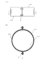
図2は、本発明における第2の好ましい実施の形態を示すものであり、食用油の保存缶の周囲に取り付ける、油の酸化防止を目的とした活性化装置2を示している。図2のAは正面図であり、BはY−Y線断面図である。本実施の形態も、図1の物体活性化装置1と同様に複数のボルト・ナット6で取り付け可能であるが、例えば外径600mmの缶に用いる場合、積層体2Bをこれに取り付け可能な600mm以上の内径を与えて筒状にする。例えば図1と同様、外層の金属板をチタンとした金属板4b、内層の金属板を銅とした金属板5bとして、その積層構造により、上記同様、炭化水素分子のクラスターが小型化されるとともに、活性化装置2による電位差により食用油がマイナスイオン化され、酸化して劣化した食用油を改質して粘度を下げたり、酸化しにくくする。尚、係る活性化装置2の金属の構成を変えてプラス電位を発生させて、油分子を凝集させることもできる。
【0018】
また、この応用例として、電位の調整により、流体中に配置した食材を固くしたり、酸化を促進して熟成させたりして風味を調整することもできる。さらに、かかる活性化装置2を所定サイズのリング形状として、ブレスレットや指輪、またはネックレスやアンクレットにすれば上記の磁力線効果による血流の改善効果やマイナスイオンによるリラックス効果を発揮させることもできる。尚、これらの装具は人間用のみならずペット用の首輪等でも同様である。
【0019】
図3は、本発明における、第3の好ましい実施の形態を示すものであり、図1の活性化装置1とは異なり、チタン粉末を練り込んだ樹脂板4cと、銅粉末を練り込んだ樹脂板5cを密着して積層した板状体3Bを有する、活性化装置3を示している。図Aは正面図であり、図BはZ−Z線断面図である。また、活性化装置3は、活性化装置1,2とはその構成が異なり、平面的なアーチ状とした積層体3Bが、枕カバー部7の頭部が当たる部分を囲むように配置された構成である。尚、係る樹脂板4c,5cは導電性を有するものとする。
【0020】
係る活性化装置3は上述の積層体と異なり、金属を粉体として柔らかい樹脂の中に練り込んで成る樹脂板を重ねて積層体3Bを形成しているため、使用中に頭に不快感を与えないものであり、これを、枕の頭が当たる部分を囲むように装着することにより、睡眠中にマイナスイオンを発生してリラックス効果が期待できるとともに、係るアーチの内側に集中して発生する磁場により頭部の血行が改善され、疲労回復効果も期待できる。尚、上記樹脂板の代わりにシート状にした金属を柔軟な樹脂板に貼り付けても同様な効果を得ることができる。
【0021】
【実施例】
本発明である、活性化装置を装着して車両の燃料消費量の改善効果を検証した実施例を示す。
装着したのは、上述の活性化装置1と同様の燃料活性化装置であって、それぞれ乗用車用には1mm,トラック用には2mmの厚さのチタンと銅の金属板を用い、大きさはエンジンの大きさと燃料輸送管のサイズに合わせて調整した。
そして、4t及び10tのディーゼルトラックと1800ccガソリンエンジン乗用車にこれを装着した場合の2ヶ月間の平均燃費と、装着しない2ヶ月間の平均燃費を調査して比較した。
【0022】
結果としては、装着した車両において装着しない同一車両に対し、10%〜35%、平均で約15%の燃費削減が認められた。加えて、排気ガスの減少・ディーゼル車の黒煙の減少も確認できた。
【0023】
尚、本発明を実施するための最良の構成は以上の記載で開示されているが、本発明はこれに限定されるものではない。
【0024】
【発明の効果】
以上のように、本発明である活性化装置により、新たなエネルギー源を必要としないで、軽量かつ簡易な構成で、水・油・空気等の物体、さらには人体を効率的に活性化することができる。
【図面の簡単な説明】
【図1】本発明における第1の好ましい実施の形態の活性化装置を示し、(A)は正面図、(B)は(A)のX−X線に沿う断面図である。
【図2】本発明における第2の好ましい実施の形態の活性化装置を示し、(A)は正面図、(B)は(A)のY−Y線に沿う断面図である。
【図3】本発明における第3の好ましい実施の形態の活性化装置を示し、(A)は正面図、(B)は(A)のZ−Z線に沿う断面図である。
【符号の説明】
1,2,3 活性化装置、1b 燃料輸送管、1B,2B,3B 積層体、4,4b,5,5b 金属板、4a,5a フランジ、4c,5c 樹脂板、6 ボルト・ナット、7 枕カバー部[0001]
BACKGROUND OF THE INVENTION
The present invention enables these functions by activating objects such as liquids such as water and oil (including volatile oils such as gasoline), gases such as air and gas, solids such as foodstuffs, and mixtures such as human bodies. It relates to an activation device for enhancing.
[0002]
[Prior art]
Conventionally, a magnetic field or electric charge is applied to a fluid such as water or fuel, and these molecular clusters are decomposed and refined to improve their reactivity, or fluid molecules are ionized to improve this. This technology has been put into practical use.
For example, in Japanese Laid-Open Patent Publication No. 7-258657, a predetermined magnetic field is generated by continuously arranging a plurality of magnetic bodies having a predetermined thickness in a direction in which magnetism repels each other, and this is used as a fuel tank. And a technique of improving the combustion efficiency by making it difficult for the hydrocarbon molecules of the fuel to be connected by the magnetic field generated thereby. In addition, the far-infrared effect of the ceramics disposed between the magnetic bodies also has the effect that the water molecules in the fuel are refined and the vaporization during spraying is further improved.
[0003]
In JP-A-5-50067, public information such as a water supply system, a positive electrode and a negative electrode having different electrochemical potentials are separated from each other in a liquid transport path through which a liquid passes, and a third electrode is further provided. From this, a technique is disclosed in which metal ions are eluted in a liquid to modify the liquid to remove the dirt components such as iron oxide scale.
Furthermore, recently, a magnetic material having a magnetic field arranged so as to sandwich the flow of water uses electromotive energy (Faraday electromagnetic induction law) by an object passing in a direction perpendicular to the magnetic field to be contained in water. There are many watering devices on the market that charge metal ions and the like, and prepare and modify water molecules.
[0004]
These technologies utilize the kinetic energy due to the flow of an object, the polarity or magnetic field of a magnetic material, and the far-infrared effect of a far-infrared ray-generating substance to ionize a fluid or arrange fluid molecules. The reform is intended.
However, since the fuel flowing through the fuel supply pipe has a very low flow velocity, the energy generated by this is extremely small, and the strength of the magnetic field generated by the magnetic material is also weak. Therefore, in order to obtain a strong magnetic field, it is necessary to use electric power applied from the outside, or to make the magnet large and strong. For this reason, the configuration becomes complicated, the size and weight become excessive, it becomes difficult to install on existing systems, and it is necessary to stop the operation for installation, so it is difficult to spread and practical. .
[0005]
On the other hand, products that improve the blood circulation by the magnetic field effect and recover fatigue by using a magnet that generates a predetermined magnetic field line on the skin or used for decorations such as necklaces and bracelets are also on the market. .
Also, a negative ion generating accessory in which a noble metal piece in which a metal having a positive potential and a metal having a negative potential are arranged to form an outer peripheral surface is connected in a row is disclosed in Japanese Patent Application Laid-Open No. 2001-218853. This uses energy such as static electricity generated by human activities and ultraviolet rays from sunlight to generate charges in a combination of metals with different potentials, and alkalizes blood with the negative ions generated by this, etc. Therefore, the blood circulation improvement effect and the relaxation effect are expected. Such a technique is an excellent technique in that energy is taken in from the outside and used as a combination of a plurality of metals having different potentials.
However, these magnetic substances and polar substances are small in one unit, and the surface area of the portion that takes in energy from the outside is small. Therefore, the generated magnetic field and the amount of negative ions are small, and it is difficult to sufficiently modify the blood.
[0006]
[Problems to be solved by the invention]
Therefore, the present invention has an object of efficiently activating an object with a simple device that does not require a new energy source and can be easily attached without disturbing the operation of each system. Improves fuel economy, makes water pipes dirty and easy to absorb in the body, prevents oxidation in oil, lowers viscosity in blood to improve circulation, and negative ionization in air This is a problem.
[0007]
[Means for Solving the Problems]
In order to solve the above-described problems, the present invention provides a method in which two or more kinds of metals having different standard electrode potentials or materials mainly containing metals are stacked on each other to generate an electric charge, whereby the stacked metals Or it was set as the activation apparatus characterized by generating electromagnetic waves by the electrical potential difference between raw materials. Thereby, even if it is a lightweight and simple structure, the energy taken in is big, and while generating a big electric potential difference and a powerful magnetic field, an ion can be generated and an object can be activated efficiently. Here, in the present invention, the material mainly containing the metal includes a mixture mainly containing an organic or inorganic metal compound and a metal.
Moreover, the said effect becomes remarkable by granulating at least 1 metal among the said 2 or more types of metals. In the present invention, the term “laminated” includes not only a state of being in close contact with each other but also a case in which a gap is provided therebetween. The granular metal can be laminated in a state where it is applied, kneaded, rubbed or woven into cloth or yarn, paper, plastic or the like.
[0008]
Further, by sandwiching at least one of ore or ceramics, or these sludges or metal sludges between the two or more kinds of metals, the metals are electrically separated or interfered with each other, and a generated magnetic field is generated. By adjusting and adjusting the activation device with enhanced far-infrared effect, it is possible to increase the efficiency of the magnetic line effect due to the magnetic field and to activate the object due to the far-infrared effect.
[0009]
Furthermore, by making the said laminated body into plate shape, strip | belt shape, or sheet shape, while extending an energy intake area, an action area can be expanded.
Furthermore, by forming the laminate into an arch shape, the magnetic field effect, far-infrared effect, and the like can be concentrated on a portion surrounded by the laminate, and the effect can be further improved by making the laminate into a tubular shape. In addition to being able to concentrate on the center, the activation device is compact and easy to mount on the curved surface of the tube. The tubular body includes small-diameter pipes and beads, but in these cases, it is easy to connect with a thread or the like, and it is easy to attach to a target object. You can also concentrate.
[0010]
If a reflector that reflects electromagnetic waves is provided on one surface of the laminate and the generated electromagnetic waves are concentrated at one or one point, the fluid can be activated more efficiently.
[0011]
DETAILED DESCRIPTION OF THE INVENTION
Hereinafter, embodiments of the present invention will be described in detail with reference to the drawings. Note that, even in different embodiments, the same components are described with the same reference numerals.
[0012]
FIG. 1 shows an
[0013]
Such an
[0014]
In addition, the combination of the metal may be other combinations as long as it exhibits a desired potential difference, and may be a combination of three or more. For example, Au and Pt are metals having a high negative potential, and Zr and Al are metals having a low negative potential (plus potential). Also, a resin plate kneaded with these oxides, carbides, and powders can be used. Depending on how they are combined, it is possible to set the direction of the polarity freely and not only to negatively ionize the fluid but also to positively ionize and agglomerate molecules to make them large molecules.
[0015]
The present embodiment is configured as described above, and has a tube structure having a two-layer structure of two kinds of metals having a potential difference, a magnetic field is generated in the fuel transport pipe 1b passing therethrough, and the fuel passes therethrough. In addition, the cluster of hydrocarbon molecules in the fuel is reduced by the action of the magnetic field, and the polarity of the polarity can be made constant by ionizing the fuel. As a result, the fuel is easily vaporized and combusted, and the combustion efficiency is improved.
[0016]
If a ceramic having a far infrared effect is sandwiched in the space between the two types of metal plates, in addition to the above effect, the fuel molecule and the water molecule contained therein are more likely to be further divided by the far infrared effect, The combustion efficiency is further improved. The energy for negative ionization of the fuel is not limited to the energy due to the movement of the fuel, but also the electromagnetic waves (such as solar-derived electromagnetic waves and cosmic rays) received by the
[0017]
FIG. 2 shows a second preferred embodiment of the present invention, and shows an
[0018]
In addition, as an application example, by adjusting the potential, it is possible to adjust the flavor by hardening the food disposed in the fluid or aging by promoting oxidation. Further, if the
[0019]
FIG. 3 shows a third preferred embodiment of the present invention. Unlike the
[0020]
Unlike the above-described laminate, the
[0021]
【Example】
An embodiment in which the activation device according to the present invention is installed and the improvement effect of the fuel consumption of the vehicle is verified will be shown.
It was equipped with a fuel activation device similar to the
Then, the average fuel consumption for two months when this was mounted on a 4t and 10t diesel truck and a 1800cc gasoline engine passenger car was compared with the average fuel consumption for two months when it was not mounted.
[0022]
As a result, a fuel consumption reduction of 10% to 35% and an average of about 15% was recognized for the same vehicle that is not mounted in the mounted vehicle. In addition, a decrease in exhaust gas and a decrease in black smoke in diesel vehicles were confirmed.
[0023]
Although the best configuration for carrying out the present invention has been disclosed in the above description, the present invention is not limited to this.
[0024]
【The invention's effect】
As described above, the activation device according to the present invention efficiently activates an object such as water, oil, air, and the human body with a light and simple configuration without requiring a new energy source. be able to.
[Brief description of the drawings]
1A and 1B show an activation device according to a first preferred embodiment of the present invention, in which FIG. 1A is a front view and FIG. 1B is a cross-sectional view taken along line XX in FIG.
FIGS. 2A and 2B show an activation device according to a second preferred embodiment of the present invention, in which FIG. 2A is a front view and FIG. 2B is a cross-sectional view taken along line YY in FIG.
FIGS. 3A and 3B show an activation device according to a third preferred embodiment of the present invention, in which FIG. 3A is a front view and FIG. 3B is a cross-sectional view taken along line ZZ in FIG.
[Explanation of symbols]
1, 2, 3 activation device, 1b fuel transport pipe, 1B, 2B, 3B laminate, 4, 4b, 5, 5b metal plate, 4a, 5a flange, 4c, 5c resin plate, 6 bolt / nut, 7 pillow Cover part
Claims (6)
Priority Applications (6)
| Application Number | Priority Date | Filing Date | Title |
|---|---|---|---|
| JP2002261085A JP2005261987A (en) | 2002-09-06 | 2002-09-06 | Activation apparatus |
| US10/526,349 US20050260109A1 (en) | 2002-09-06 | 2003-09-05 | Activation apparatus |
| JP2004534171A JPWO2004022222A1 (en) | 2002-09-06 | 2003-09-05 | Activation device |
| AU2003261955A AU2003261955A1 (en) | 2002-09-06 | 2003-09-05 | Activation apparatus |
| EP03794250A EP1547680A4 (en) | 2002-09-06 | 2003-09-05 | Activation apparatus |
| PCT/JP2003/011349 WO2004022222A1 (en) | 2002-09-06 | 2003-09-05 | Activation apparatus |
Applications Claiming Priority (1)
| Application Number | Priority Date | Filing Date | Title |
|---|---|---|---|
| JP2002261085A JP2005261987A (en) | 2002-09-06 | 2002-09-06 | Activation apparatus |
Publications (1)
| Publication Number | Publication Date |
|---|---|
| JP2005261987A true JP2005261987A (en) | 2005-09-29 |
Family
ID=31973114
Family Applications (2)
| Application Number | Title | Priority Date | Filing Date |
|---|---|---|---|
| JP2002261085A Pending JP2005261987A (en) | 2002-09-06 | 2002-09-06 | Activation apparatus |
| JP2004534171A Pending JPWO2004022222A1 (en) | 2002-09-06 | 2003-09-05 | Activation device |
Family Applications After (1)
| Application Number | Title | Priority Date | Filing Date |
|---|---|---|---|
| JP2004534171A Pending JPWO2004022222A1 (en) | 2002-09-06 | 2003-09-05 | Activation device |
Country Status (5)
| Country | Link |
|---|---|
| US (1) | US20050260109A1 (en) |
| EP (1) | EP1547680A4 (en) |
| JP (2) | JP2005261987A (en) |
| AU (1) | AU2003261955A1 (en) |
| WO (1) | WO2004022222A1 (en) |
Cited By (1)
| Publication number | Priority date | Publication date | Assignee | Title |
|---|---|---|---|---|
| JP2018059909A (en) * | 2016-10-04 | 2018-04-12 | 株式会社ランドマスター・ジャパン | Substance activation member |
Families Citing this family (3)
| Publication number | Priority date | Publication date | Assignee | Title |
|---|---|---|---|---|
| WO2007053063A1 (en) * | 2005-11-02 | 2007-05-10 | Abramov, Oleg Aleksandrovich | Hydrocarbon raw-material processing device |
| JP2007255261A (en) * | 2006-03-22 | 2007-10-04 | Rikka:Kk | Noncontact type fuel reformer and system |
| JP2019000843A (en) * | 2017-06-13 | 2019-01-10 | 石黒 三郎 | Water reformer |
Citations (25)
| Publication number | Priority date | Publication date | Assignee | Title |
|---|---|---|---|---|
| JPS6023999A (en) * | 1983-07-19 | 1985-02-06 | 三協電業株式会社 | Activating device |
| JPS6133289A (en) * | 1984-07-25 | 1986-02-17 | Kazue Hitomi | Fluid activating apparatus |
| JPS6133290A (en) * | 1984-07-25 | 1986-02-17 | Kazue Hitomi | Apparatus for improving water quality of potable water |
| JPS62107752A (en) * | 1985-11-06 | 1987-05-19 | Nobukatsu Baba | Removal of molecular oxidation by line of magnetic force |
| JPS62155934A (en) * | 1985-12-28 | 1987-07-10 | Canon Inc | Vapor phase exciter |
| JPS63106361A (en) * | 1986-07-23 | 1988-05-11 | Yuu Kosan Kk | Method of activating gasoline mixture and device therefor |
| JPH01192542A (en) * | 1988-01-28 | 1989-08-02 | Yasuro Kuratomi | Far infrared ray irradiating plate |
| JPH02206690A (en) * | 1989-02-06 | 1990-08-16 | Hideyo Tada | Fuel activation method and activation system |
| JPH0441967A (en) * | 1990-06-01 | 1992-02-12 | Etsuro Fujita | Combustion activating device |
| JPH05149203A (en) * | 1991-11-22 | 1993-06-15 | Fusamitsu Koga | Engine performance improving device |
| JPH0775709A (en) * | 1993-06-18 | 1995-03-20 | Yuuji Otome | Electrolytic filter |
| JPH07145758A (en) * | 1993-11-24 | 1995-06-06 | Etsuro Fujita | Combustion activating device |
| JPH07275863A (en) * | 1994-04-13 | 1995-10-24 | Shigeaki Togawa | Laminated filter for water purifying treatment |
| JPH08155442A (en) * | 1994-12-07 | 1996-06-18 | Baiotsukusu:Kk | Water activating treatment apparatus |
| JPH09141269A (en) * | 1995-11-24 | 1997-06-03 | Tatsuhiko Ogawa | Treatment of water and device therefor |
| JPH10165958A (en) * | 1996-12-05 | 1998-06-23 | De-La:Kk | Magnetic water-treating apparatus enhancing magnetic treatment effect of water |
| JPH1190452A (en) * | 1997-09-17 | 1999-04-06 | Kiyomi Ikejima | Magnetized water producing apparatus |
| JPH11147089A (en) * | 1997-11-14 | 1999-06-02 | Biox Giken:Kk | Water activating apparatus |
| JPH11235525A (en) * | 1998-02-23 | 1999-08-31 | Yamamoto Vinita Co Ltd | Material activation promoting method by electromagnetic wave and device therefor |
| JP2000019296A (en) * | 1998-04-28 | 2000-01-21 | Wfn:Kk | Method and device for activating substance |
| JP2001221109A (en) * | 2000-02-08 | 2001-08-17 | Niles Parts Co Ltd | Internal combustion engine and automobile |
| JP2002055198A (en) * | 2000-08-10 | 2002-02-20 | Wfn:Kk | Substance activating device |
| JP2002079253A (en) * | 2000-09-07 | 2002-03-19 | Kido Toshihiro | Water cleaning method and water cleaning instrument |
| WO2002060576A1 (en) * | 2001-01-30 | 2002-08-08 | Honda Giken Kogyo Kabushiki Kaisha | Active structure, apparatus for activating substance, and method of activating substance |
| JP2002525495A (en) * | 1998-09-28 | 2002-08-13 | ウェイ,アルバート・シー | Fuel activation device |
Family Cites Families (11)
| Publication number | Priority date | Publication date | Assignee | Title |
|---|---|---|---|---|
| US3286259A (en) * | 1964-04-30 | 1966-11-15 | Goodyear Aerospace Corp | Unfurlable reflector |
| JPH07326395A (en) * | 1994-05-31 | 1995-12-12 | Yuji Hara | Energy feed device |
| US5738931A (en) * | 1994-09-16 | 1998-04-14 | Kabushiki Kaisha Toshiba | Electronic device and magnetic device |
| JP2000084558A (en) * | 1998-09-11 | 2000-03-28 | Sunao Kono | Production of electrolytic water and electrolytic water production device |
| GB2346528A (en) * | 1999-01-21 | 2000-08-09 | Aea Technology Plc | Power supply for processing of gaseous media |
| DE19920885C1 (en) * | 1999-05-06 | 2001-03-22 | Daimler Chrysler Ag | Chemical actuator |
| JP2002174149A (en) * | 2000-09-29 | 2002-06-21 | Ii M Kenkyu Kiko Kk | Liquid fuel reformer and internal combustion engine |
| US20040005242A1 (en) * | 2000-10-27 | 2004-01-08 | Pavel Koulik | Method and device for sterilising a liquid |
| JP3079676U (en) * | 2001-02-06 | 2001-08-31 | 株式会社ダイシンテクノサービス | Energy emitter mounting |
| US6562386B2 (en) * | 2001-05-07 | 2003-05-13 | Regents Of The University Of Minnesota | Method and apparatus for non-thermal pasteurization |
| DE10154762A1 (en) * | 2001-11-09 | 2003-05-22 | Peter Swoboda | Process for changing the physical properties of liquids, especially water, comprises irradiating the liquid directly or a carrier liquid with electromagnetic waves |
-
2002
- 2002-09-06 JP JP2002261085A patent/JP2005261987A/en active Pending
-
2003
- 2003-09-05 JP JP2004534171A patent/JPWO2004022222A1/en active Pending
- 2003-09-05 AU AU2003261955A patent/AU2003261955A1/en not_active Abandoned
- 2003-09-05 WO PCT/JP2003/011349 patent/WO2004022222A1/en not_active Application Discontinuation
- 2003-09-05 EP EP03794250A patent/EP1547680A4/en not_active Withdrawn
- 2003-09-05 US US10/526,349 patent/US20050260109A1/en not_active Abandoned
Patent Citations (25)
| Publication number | Priority date | Publication date | Assignee | Title |
|---|---|---|---|---|
| JPS6023999A (en) * | 1983-07-19 | 1985-02-06 | 三協電業株式会社 | Activating device |
| JPS6133289A (en) * | 1984-07-25 | 1986-02-17 | Kazue Hitomi | Fluid activating apparatus |
| JPS6133290A (en) * | 1984-07-25 | 1986-02-17 | Kazue Hitomi | Apparatus for improving water quality of potable water |
| JPS62107752A (en) * | 1985-11-06 | 1987-05-19 | Nobukatsu Baba | Removal of molecular oxidation by line of magnetic force |
| JPS62155934A (en) * | 1985-12-28 | 1987-07-10 | Canon Inc | Vapor phase exciter |
| JPS63106361A (en) * | 1986-07-23 | 1988-05-11 | Yuu Kosan Kk | Method of activating gasoline mixture and device therefor |
| JPH01192542A (en) * | 1988-01-28 | 1989-08-02 | Yasuro Kuratomi | Far infrared ray irradiating plate |
| JPH02206690A (en) * | 1989-02-06 | 1990-08-16 | Hideyo Tada | Fuel activation method and activation system |
| JPH0441967A (en) * | 1990-06-01 | 1992-02-12 | Etsuro Fujita | Combustion activating device |
| JPH05149203A (en) * | 1991-11-22 | 1993-06-15 | Fusamitsu Koga | Engine performance improving device |
| JPH0775709A (en) * | 1993-06-18 | 1995-03-20 | Yuuji Otome | Electrolytic filter |
| JPH07145758A (en) * | 1993-11-24 | 1995-06-06 | Etsuro Fujita | Combustion activating device |
| JPH07275863A (en) * | 1994-04-13 | 1995-10-24 | Shigeaki Togawa | Laminated filter for water purifying treatment |
| JPH08155442A (en) * | 1994-12-07 | 1996-06-18 | Baiotsukusu:Kk | Water activating treatment apparatus |
| JPH09141269A (en) * | 1995-11-24 | 1997-06-03 | Tatsuhiko Ogawa | Treatment of water and device therefor |
| JPH10165958A (en) * | 1996-12-05 | 1998-06-23 | De-La:Kk | Magnetic water-treating apparatus enhancing magnetic treatment effect of water |
| JPH1190452A (en) * | 1997-09-17 | 1999-04-06 | Kiyomi Ikejima | Magnetized water producing apparatus |
| JPH11147089A (en) * | 1997-11-14 | 1999-06-02 | Biox Giken:Kk | Water activating apparatus |
| JPH11235525A (en) * | 1998-02-23 | 1999-08-31 | Yamamoto Vinita Co Ltd | Material activation promoting method by electromagnetic wave and device therefor |
| JP2000019296A (en) * | 1998-04-28 | 2000-01-21 | Wfn:Kk | Method and device for activating substance |
| JP2002525495A (en) * | 1998-09-28 | 2002-08-13 | ウェイ,アルバート・シー | Fuel activation device |
| JP2001221109A (en) * | 2000-02-08 | 2001-08-17 | Niles Parts Co Ltd | Internal combustion engine and automobile |
| JP2002055198A (en) * | 2000-08-10 | 2002-02-20 | Wfn:Kk | Substance activating device |
| JP2002079253A (en) * | 2000-09-07 | 2002-03-19 | Kido Toshihiro | Water cleaning method and water cleaning instrument |
| WO2002060576A1 (en) * | 2001-01-30 | 2002-08-08 | Honda Giken Kogyo Kabushiki Kaisha | Active structure, apparatus for activating substance, and method of activating substance |
Cited By (1)
| Publication number | Priority date | Publication date | Assignee | Title |
|---|---|---|---|---|
| JP2018059909A (en) * | 2016-10-04 | 2018-04-12 | 株式会社ランドマスター・ジャパン | Substance activation member |
Also Published As
| Publication number | Publication date |
|---|---|
| EP1547680A1 (en) | 2005-06-29 |
| US20050260109A1 (en) | 2005-11-24 |
| AU2003261955A1 (en) | 2004-03-29 |
| WO2004022222A1 (en) | 2004-03-18 |
| JPWO2004022222A1 (en) | 2005-12-22 |
| EP1547680A4 (en) | 2007-03-07 |
Similar Documents
| Publication | Publication Date | Title |
|---|---|---|
| US3844741A (en) | Air purifier | |
| CN103830989B (en) | The method for administering haze and room air pollution with tourmaline matter honeycomb ceramics | |
| Liu et al. | Triboelectric filtering for air purification | |
| JP2005261987A (en) | Activation apparatus | |
| US6709490B1 (en) | Combined system for removing contaminants from gas effluents | |
| EP2453114A1 (en) | Exhaust gas purification method and system | |
| US20080241004A1 (en) | Plasma actuated electronic catalytic converter | |
| KR20060115830A (en) | Fuel saving device for vehicle | |
| JP3443733B2 (en) | Exhaust gas purification device for diesel automobile engine | |
| Yea et al. | All-solid-state Z-scheme ZnFe–LDH/rGO/g-C3N5 heterojunction for enhanced sonophotocatalytic degradation of ciprofloxacin: Performance and mechanistic insights | |
| EP2119901A1 (en) | Environment protective and energy saving type filter for internal combustion engine | |
| JP2001212452A (en) | FLUID TREATING DEVICE USING MAGNETIC FIELD, alpha RAY AND FAR- INFRARED RAYS | |
| AU715154B2 (en) | Filter apparatus with induced voltage electrode and method | |
| RU2708218C2 (en) | Method for optimizing combustion in fuel combustion devices and device for carrying out method | |
| JP2000161154A (en) | Fuel comsumption improving device for internal combustion engine | |
| JP4287115B2 (en) | Feed fuel oil reformer | |
| JPH11128658A (en) | Exhaust gas treating device | |
| JP2001065416A (en) | Fuel consumption improving device for internal combustion engine | |
| JP2822275B2 (en) | Magnetic flux density amplifying device | |
| JP2011140893A (en) | Combustion promoting device of internal combustion engine | |
| WO2004102716A3 (en) | Fuel cell system and vehicle with fuel cell system mounted thereon | |
| TWM551653U (en) | Molecule minimizing device for oil product | |
| KR200183419Y1 (en) | Fuel economizing apparatus | |
| JP2019157716A (en) | Plasma reactor | |
| CN105626323A (en) | Oil-gas complete combustion and compartment air purifying system of vehicle |
Legal Events
| Date | Code | Title | Description |
|---|---|---|---|
| A711 | Notification of change in applicant |
Free format text: JAPANESE INTERMEDIATE CODE: A711 Effective date: 20050804 |
|
| A521 | Written amendment |
Free format text: JAPANESE INTERMEDIATE CODE: A821 Effective date: 20050804 |
|
| A621 | Written request for application examination |
Free format text: JAPANESE INTERMEDIATE CODE: A621 Effective date: 20050906 |
|
| A131 | Notification of reasons for refusal |
Free format text: JAPANESE INTERMEDIATE CODE: A131 Effective date: 20080826 |
|
| A521 | Written amendment |
Free format text: JAPANESE INTERMEDIATE CODE: A523 Effective date: 20081006 |
|
| A131 | Notification of reasons for refusal |
Free format text: JAPANESE INTERMEDIATE CODE: A131 Effective date: 20081104 |
|
| A521 | Written amendment |
Free format text: JAPANESE INTERMEDIATE CODE: A523 Effective date: 20090105 |
|
| A131 | Notification of reasons for refusal |
Free format text: JAPANESE INTERMEDIATE CODE: A131 Effective date: 20090811 |
|
| A521 | Written amendment |
Free format text: JAPANESE INTERMEDIATE CODE: A523 Effective date: 20091013 |
|
| A131 | Notification of reasons for refusal |
Free format text: JAPANESE INTERMEDIATE CODE: A131 Effective date: 20091208 |
|
| A02 | Decision of refusal |
Free format text: JAPANESE INTERMEDIATE CODE: A02 Effective date: 20100323 |