JP2005259256A - Disk device increasing heat radiating effect - Google Patents

Disk device increasing heat radiating effect Download PDF

Info

Publication number
JP2005259256A
JP2005259256A JP2004069233A JP2004069233A JP2005259256A JP 2005259256 A JP2005259256 A JP 2005259256A JP 2004069233 A JP2004069233 A JP 2004069233A JP 2004069233 A JP2004069233 A JP 2004069233A JP 2005259256 A JP2005259256 A JP 2005259256A
Authority
JP
Japan
Prior art keywords
disk
circuit board
disk device
heat
frame
Prior art date
Legal status (The legal status is an assumption and is not a legal conclusion. Google has not performed a legal analysis and makes no representation as to the accuracy of the status listed.)
Withdrawn
Application number
JP2004069233A
Other languages
Japanese (ja)
Other versions
JP2005259256A5 (en
Inventor
Yasuo Hamazaki
恭雄 濱崎
Toshihiro Tamura
俊宏 田村
Current Assignee (The listed assignees may be inaccurate. Google has not performed a legal analysis and makes no representation or warranty as to the accuracy of the list.)
Orion Electric Co Ltd
Original Assignee
Orion Electric Co Ltd
Priority date (The priority date is an assumption and is not a legal conclusion. Google has not performed a legal analysis and makes no representation as to the accuracy of the date listed.)
Filing date
Publication date
Application filed by Orion Electric Co Ltd filed Critical Orion Electric Co Ltd
Priority to JP2004069233A priority Critical patent/JP2005259256A/en
Publication of JP2005259256A publication Critical patent/JP2005259256A/en
Publication of JP2005259256A5 publication Critical patent/JP2005259256A5/ja
Withdrawn legal-status Critical Current

Links

Images

Abstract

<P>PROBLEM TO BE SOLVED: To effectively suppress heat generation of a circuit substrate without spoiling the thinner shape of a disk device. <P>SOLUTION: A circuit substrate 6 is fixed between side wall sections 7B and 7B and a ventilation path 28 is formed by a space section 27 surrounded by the circuit substrate 6 and the side wall section 7B so as to cause the air movement caused by the rotation of a disk 2. Electronic parts 18 and 18A packaged on the circuit substrate 6 are faced toward the disk 2 side and fixed to a frame 7 so as to face the ventilation path 28. Thus, air flow caused by the rotation of the disk 2 passes through the ventilation path 28, exhausted to the external and heat from the heat generating electronic part 18A packaged on the circuit substrate 6 is radiated to the external. <P>COPYRIGHT: (C)2005,JPO&NCIPI

Description

本発明は、ディスクの記録面にレーザー光を照射してディスクの記録/再生を行うディスク装置、特に、ディスクの回転時に発生する空気の流れを利用して回路基板に実装する電子部品の発熱を効果的に抑えるようにした放熱効果を高めたディスク装置に関する。   The present invention relates to a disk device that records / reproduces a disk by irradiating the recording surface of the disk with a laser beam, and more particularly to heat generation of an electronic component mounted on a circuit board using a flow of air generated when the disk rotates. The present invention relates to a disk device with an improved heat dissipation effect that is effectively suppressed.

近年、ディスク装置は、ユーザーの種々のニーズに対応して、DVDプレーヤやCDプレーヤ等に限られず、テレビジョン受像機本体にも内蔵されるなど、その使用範囲は広範囲に及んでいる。これらのディスク装置は、年々小型、薄型化が進み、内部においては空間的な余裕がなく、種々の装置や部品が高密度で装着されている一方、内部に収納された駆動制御回路のICの電子部品などからの発熱密度が増加している。このため、ディスクの書き込み、読み込み動作における温度上昇による誤動作を防止することが重要な課題になっている。このような、従来技術の光ディスク装置の放熱構造として、例えば、特許文献1、2には、メカシャーシによってケーシング内を上下に仕切るとともに、上側区画エリアにディスクを載置するトレー、ターンテーブル、ターンテーブルを駆動するモータ、ディスクの記録面に光を照射してデータを読み取るピックアップ、このピックアップをディスクの半径方向に移動させるためのトラバースユニットなどのディスク装置の主要ユニットを配置し、下側区画エリアにピックアップや駆動機構の駆動及び制御するLSI、IC等の発熱電子部品が実装された回路基板を配置し、ディスクの回転によって上側区画エリアに発生する空気の流れを利用し、その空気を下側区画エリアに循環させるディスク装置の冷却装置が開示されている。すなわち、これら特許文献1、2は、上下の区画エリアを仕切るメカシャーシに複数の通風口を形成し、ディスクの回転によって上側区画エリア内を流れる空気を通風口からに下側区画エリアへと通過させ、通風口から再び上側の区画エリアへと循環させることによって、回路基板に実装した発熱電子部品の冷却効果を高めるようにしている。   In recent years, disk devices are not limited to DVD players, CD players, etc., and are used in a television receiver body in response to various needs of users. These disk devices are becoming smaller and thinner year by year, and there is no space in the interior, and various devices and parts are mounted at high density, while the IC of the drive control circuit housed inside The heat generation density from electronic parts is increasing. For this reason, it has become an important issue to prevent malfunctions due to temperature rise in disk writing and reading operations. As such a heat dissipation structure of a conventional optical disk device, for example, in Patent Documents 1 and 2, the casing is vertically divided by a mechanical chassis, and a tray, a turntable, and a turn for placing a disk in the upper partition area are disclosed. The lower partition area is equipped with the main unit of the disk device, such as a motor that drives the table, a pickup that irradiates light onto the recording surface of the disk, and a traverse unit for moving this pickup in the radial direction of the disk. A circuit board on which heat generating electronic parts such as LSIs and ICs for driving and controlling the pickup and the driving mechanism are mounted is arranged on the upper side, and the air flow generated in the upper section area by the rotation of the disk is used to move the air to the lower side. A cooling device for a disk device that circulates in a partition area is disclosed. That is, these Patent Documents 1 and 2 form a plurality of ventilation openings in a mechanical chassis that partitions the upper and lower division areas, and passes air flowing in the upper division area from the ventilation opening to the lower division area by rotating the disk. The cooling effect of the heat-generating electronic components mounted on the circuit board is enhanced by circulating the air from the ventilation port to the upper partition area again.

特開2000−231782公報Japanese Patent Laid-Open No. 2000-231782 特開2000−231783公報JP 2000-231783 A

このように、特許文献1または特許文献2では、ディスクの回転によって発生する空気の流れを利用して回路基板を冷却するように構成することによって、別途、冷却ファンなど冷却部品を組み込む必要がないから、ディスク装置をコンパクトに小型化できるという利点を有するものの、ケーシングをメカシャーシによってケーシングを上下に区画し、上側区画エリアにディスク装置の主要ユニットを収納し、下側区画エリアに集積回路などが実装された回路基板を収納することから、ディスク装置を薄型化するには限界があり、ディスク装置を薄型化することができない、という課題を有している。   As described above, in Patent Document 1 or Patent Document 2, it is not necessary to separately incorporate a cooling component such as a cooling fan by configuring the circuit board to be cooled by using the air flow generated by the rotation of the disk. The disk device can be compactly downsized, but the casing is divided into upper and lower sections by a mechanical chassis, the main unit of the disk device is stored in the upper partition area, and an integrated circuit is provided in the lower partition area. Since the mounted circuit board is accommodated, there is a limit to making the disk device thinner, and there is a problem that the disk device cannot be made thinner.

本発明は上述した問題点に鑑みてなされたものであり、ディスク装置の薄型化を損なうことなく、回路基板に実装した電子部品の発熱を効果的に抑えることができる放熱効果を高めたディスク装置を提供することを目的とする。   The present invention has been made in view of the above-described problems, and has improved the heat dissipation effect that can effectively suppress the heat generation of the electronic component mounted on the circuit board without impairing the thinning of the disk device. The purpose is to provide.

請求項1の放熱効果を高めたディスク装置は、ディスクを搬入/搬出するトレイと、前記ディスクを回転駆動するターンテーブルと、前記ディスクの記録面にレーザー光を照射して前記ディスクの記録/再生を行うピックアップレンズと、ディスク装置を制御する回路基板と、これら構成部品を組付けるフレームとを備えたディスク装置であって、前記フレームは、対向する一対の側壁部を備え、この側壁部の上面に前記回路基板を掛け渡して該側壁部と前記回路基板とで囲まれた空間部に前記ディスクの回転時に発生する空気が流れる通風路を形成するとともに、この通風路に臨ませるように、前記回路基板の実装面を前記ディスク側に向けて取り付けたことを特徴とする。   The disk device with enhanced heat dissipation effect according to claim 1 is a tray for loading / unloading a disk, a turntable for rotationally driving the disk, and recording / reproducing of the disk by irradiating a recording surface of the disk with laser light. A pickup lens, a circuit board for controlling the disk device, and a frame for assembling these components. The frame includes a pair of opposing side wall portions, and an upper surface of the side wall portion. The circuit board is stretched over to form a ventilation path through which air generated during rotation of the disk flows in a space surrounded by the side wall and the circuit board, and so as to face the ventilation path, The mounting surface of the circuit board is mounted facing the disk side.

請求項1の構成によれば、ディスクの回転より生じる空気が通風路を通ってフレームから外部に抜ける際、回路基板に実装された電子部品、特に、各種モータ等を駆動するドライバーや諸制御を行うなどの発熱電子部品からの熱が外部に放熱される。さらに、単に回路基板をフレームの上面に固定するだけなので、ディスク装置全体の高さ寸法の抑えることが可能となり、ディスク装置を可及的に薄型化することができる。   According to the first aspect of the present invention, when the air generated by the rotation of the disk passes through the ventilation path to the outside from the frame, the electronic components mounted on the circuit board, in particular, drivers for driving various motors and various controls are provided. Heat from the exothermic electronic components is radiated to the outside. Furthermore, since the circuit board is simply fixed to the upper surface of the frame, the overall height of the disk device can be suppressed, and the disk device can be made as thin as possible.

請求項2の放熱効果を高めたディスク装置は、請求項1記載の放熱効果を高めたディスク装置において、前記回路基板に実装する電子部品に近接させて放熱板を設けるとともに、この放熱板には、前記電子部品を覆う平板部と、前記回路基板に固定する脚部を備えるとともに、前記平板部に傾斜面を備えた段差凹部を形成したことを特徴とする。   According to a second aspect of the present invention, there is provided a disk device having an improved heat dissipation effect. In the disk device having an increased heat dissipation effect according to the first aspect, a heat sink is provided in proximity to the electronic component mounted on the circuit board. The flat plate portion covering the electronic component and the leg portion fixed to the circuit board are provided, and the flat plate portion is formed with a step recess having an inclined surface.

請求項2の構成によれば、電子部品からの熱が放熱板に効果的に伝熱され、かつ、放熱板は、その放熱面積を拡大するように、電子部品を覆う平板部に傾斜面を有する段差凹部が形成されているため、放熱板の放熱効果が向上し、より効果的に電子部品から発散する熱が放熱される。   According to the configuration of claim 2, heat from the electronic component is effectively transferred to the heat radiating plate, and the heat radiating plate has an inclined surface on the flat plate portion covering the electronic component so as to expand the heat radiating area. Since the stepped concave portion is formed, the heat dissipation effect of the heat radiating plate is improved, and the heat dissipated from the electronic component is radiated more effectively.

請求項3の放熱効果を高めたディスク装置は、請求項2記載の放熱効果を高めたディスク装置において、前記段差凹部に複数の通気孔を設けたことを特徴とする。   According to a third aspect of the present invention, there is provided a disc apparatus having an improved heat dissipation effect, wherein the stepped recess is provided with a plurality of air holes.

請求項3の構成によれば、ディスクの回転より生じる空気が通気孔を通って電子部品の周囲を流れ、電子部品の放熱効果が高まる。   According to the configuration of the third aspect, air generated by the rotation of the disk flows around the electronic component through the vent hole, and the heat dissipation effect of the electronic component is enhanced.

本発明の請求項1の放熱効果を高めたディスク装置によれば、ディスクを搬入/搬出するトレイと、前記ディスクを回転駆動するターンテーブルと、前記ディスクの記録面にレーザー光を照射して前記ディスクの記録/再生を行うピックアップレンズと、ディスク装置を制御する回路基板と、これら構成部品を組付けるフレームとを備えたディスク装置であって、前記フレームは、対向する一対の側壁部を備え、この側壁部の上面に前記回路基板を掛け渡して該側壁部と前記回路基板とで囲まれた空間部に前記ディスクの回転時に発生する空気が流れる通風路を形成するとともに、この通風路に臨ませるように、前記回路基板の実装面を前記ディスク側に向けて取り付けたものであるから、ディスクの回転より生じる空気が通風路を通ってフレームのから外部に抜ける際、回路基板に実装された電子部品、特に、各種モータ等を駆動するドライバーや諸制御を行うなどの発熱電子部品からの熱を外部に放熱することができる。これにより、発熱電子部品からの熱が篭らず、回路基板に実装した電子部品を効率的に放熱することが可能となる。また、通風路は、ディスク装置の構成上、必要不可欠な回路基板をフレームに固定して形成することから、新たに放熱部品を用いる必要がないとともに、単に回路基板をフレームの上面に固定するだけなので、ディスク装置全体の高さ寸法の抑えることが可能である。   According to the disk device with improved heat dissipation effect of the first aspect of the present invention, the tray for loading / unloading the disk, the turntable for rotating the disk, and the recording surface of the disk are irradiated with laser light to A disc device comprising a pickup lens for recording / reproducing a disc, a circuit board for controlling the disc device, and a frame for assembling these components, the frame comprising a pair of opposing side wall portions, The circuit board is hung on the upper surface of the side wall, and a ventilation path through which air generated when the disk rotates is formed in a space surrounded by the side wall and the circuit board. Since the mounting surface of the circuit board is mounted toward the disk so that the air is generated by the rotation of the disk, the air flows through the ventilation path. When exiting from the over arm to the outside, the electronic components mounted on the circuit board, in particular, the heat from the heat generating electronic components, such as performing the drivers and various control for driving the various motors and the like can be radiated to the outside. As a result, heat from the heat-generating electronic component is not lost, and the electronic component mounted on the circuit board can be efficiently radiated. In addition, the ventilation path is formed by fixing the circuit board, which is indispensable to the structure of the disk device, to the frame, so there is no need to use a new heat dissipating part, and the circuit board is simply fixed to the upper surface of the frame. Therefore, it is possible to suppress the height dimension of the entire disk device.

請求項2の放熱効果を高めたディスク装置によれば、請求項1記載の放熱効果を高めたディスク装置において、基板に前記回路基板に実装する電子部品に近接させて放熱板を設けるとともに、この放熱板には、前記電子部品を覆う平板部と、前記回路基板に固定する脚部を備えるとともに、前記平板部に傾斜面を備えた段差凹部を形成したものであるから、傾斜面を備えた段差凹部により、放熱板の放熱面積を拡大することができ、電子部品から発散された熱が放熱板へと効率的に伝わり、ディスクの回転より生じる空気が通風路を通ってフレームのから外部に抜ける際、回路基板に実装された電子部品、特に、各種モータ等を駆動するドライバーや諸制御を行うなどの発熱電子部品が発する熱を外部へと効率的に放熱することができる。   According to the disk device with improved heat dissipation effect of claim 2, in the disk device with improved heat dissipation effect according to claim 1, a heat sink is provided on the substrate in the vicinity of the electronic component mounted on the circuit board, The heat radiating plate includes a flat plate portion that covers the electronic component, and a leg portion that is fixed to the circuit board, and a stepped concave portion that includes an inclined surface on the flat plate portion. The step recess allows the heat dissipation area of the heat sink to be expanded, the heat dissipated from the electronic components is efficiently transferred to the heat sink, and the air generated by the rotation of the disk passes through the ventilation path from the frame to the outside. At the time of removal, the heat generated by the electronic components mounted on the circuit board, particularly the heat generating electronic components such as drivers for driving various motors and various controls, can be efficiently radiated to the outside.

請求項3の放熱効果を高めたディスク装置によれば、請求項2記載の放熱効果を高めたディスク装置において、前記段差凹部に複数の通気孔を設けたものであるから、ディスクの回転より生じる空気が通気孔を通って電子部品の周囲を流れることから電子部品から発散する熱及び放熱板に伝わる熱を効率的に放熱することができる。   According to the disk device with enhanced heat dissipation effect of claim 3, in the disk device with enhanced heat dissipation effect according to claim 2, the plurality of vent holes are provided in the stepped recess, and therefore the rotation is caused by rotation of the disk. Since air flows around the electronic component through the vent hole, heat radiated from the electronic component and heat transmitted to the heat radiating plate can be efficiently radiated.

以下、本発明の具体的実施例について、添付図面を参照しながら説明する。なお、以下の実施態様は、本発明を具体化する際の一形態であって、本発明をその範囲内に限定するためのものではない。   Specific embodiments of the present invention will be described below with reference to the accompanying drawings. The following embodiment is one form when the present invention is embodied, and is not intended to limit the present invention within the scope thereof.

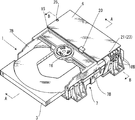
図1〜図8に示すように、本実施例のディスク装置1は、ディスク2を搬入/搬出するトレイ3と、ディスク2を回転駆動するターンテーブル4と、ディスク2の半径方向へ進退可能に設けたピックアップレンズ5と、ディスク装置1を駆動、制御するための回路が形成された回路基板6などを主要構成部品とし、これら主要構成部品を合成樹脂製のフレーム7に組付けている。また、前記ターンテーブル4とピックアップレンズ5及びその送り機構8は金属製の支持フレーム9に固定して一体的にユニット化したメカユニット10としている。また、前記フレーム7は、水平方向に延びる支持枠7Aと、この支持枠7Aの左右両側に一体形成する側壁部7Bとで構成され、前記支持枠7Aに形成する開口部7Cに臨ませて前記メカユニット10を固定するとともに、側壁部7Bの内面に前記トレイ3を案内するレール12を形成し、このレール12に沿わせてトレイ3をフレーム7に対して前後方向に移動するように構成している。   As shown in FIGS. 1 to 8, the disk device 1 of the present embodiment is capable of moving back and forth in the radial direction of the disk 2, a tray 3 for loading / unloading the disk 2, a turntable 4 for rotating the disk 2, and the disk 2. A pickup lens 5 provided, a circuit board 6 on which a circuit for driving and controlling the disk device 1 is formed as main components, and these main components are assembled to a frame 7 made of synthetic resin. The turntable 4, the pickup lens 5, and the feed mechanism 8 are fixed to a metal support frame 9 as a mechanical unit 10 that is integrated as a unit. The frame 7 includes a support frame 7A extending in the horizontal direction and side wall portions 7B integrally formed on both left and right sides of the support frame 7A. The frame 7 faces the opening 7C formed in the support frame 7A. In addition to fixing the mechanical unit 10, a rail 12 for guiding the tray 3 is formed on the inner surface of the side wall 7B, and the tray 3 is moved along the rail 12 in the front-rear direction with respect to the frame 7. ing.

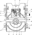
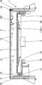
前記ターンテーブル4は、前記フレーム7のほぼ中央部に配置されたスピンドルモータ14の回転駆動によって回転するように構成され、このターンテーブル4の上方に位置して前記フレーム7の側壁部7Bの間に帯板状の支持板15が一体的に架設されている。この支持板15の中央部にはクランパ16が固定されており、このクランパ16とターンテーブル4とでディスク2を挟持して、ディスク2が回転するように構成されている。そして、前記支持板15の後方に各種の電子部品18が実装された回路基板6が配置されている。回路基板6は、前記左右の側壁部7Bの上面に掛け渡してフレーム7に固定されており、前記フレーム7の支持板15には、回路基板6を係止するL型の係止爪20が一体形成されるとともに、フレーム7の側壁部7B,7Bには回路基板6を固定する位置決めピン21及び固定孔22が形成されている。一方、前記回路基板6には前記位置決めピン21と固定孔22に対応する位置にそれぞれ孔部23,23が形成され、回路基板6の前端部を係止爪20に係止した状態で位置決めピン21を一方の孔部23に嵌め入れ、他方の孔部23に挿入した固定ビス25を固定孔22にねじ込むことによってフレーム7に回路基板6を固定している。ここで、回路基板6は、その回路基板6に実装した電子部品18が前記ディスク2側、すなわち、内面側に向くようにして前記フレーム7の側壁部7B,7B間に固定され、このようにして側壁部7B,7B間に固定した回路基板6によって、フレーム7の上面開放部分を覆うことによって、ディスク2を格納した状態において回路基板6とフレーム7の側壁部7Bによって囲まれた空間部27が形成され、この空間部27によって前記ディスク2の回転より生じる空気が流れる通風路28が形成されることになる。なお、前記フレーム7に固定される回路基板6の一側には、フラットケーブル18Bが集約的にコネクタ18Cを介して接続され、このフラットケーブル18Bが前記メカユニット14などと電気的に接続されている。また、前記回路基板6に実装する電子部品18のうち、特に、各種モータ等を駆動するドライバーICや諸制御を行うLSIなどの発熱電子部品18Aには、これを覆うように熱伝導に優れた金属製薄板から成る放熱板30が設けられている。この放熱板30は、平面からみて矩形状に形成された平板部31と、この平板部31の各コーナー部分から垂設した4本の脚部32とを有し、前記平板部31で発熱電子部品18Aを覆うようにして前記回路基板6に各脚部32を半田付けなどの適宜手段によって固定している。また、前記平板部31には、発熱電子部品18A側に向かって凹んだ段差凹部33が形成されている。この段差凹部33は、一対の通気孔34を有する面板部35と、この面板部35に両側に連設するテーパ状の傾斜面36,36とで構成され、このように、発熱電子部品18Aを覆う平板部31に傾斜面36,36を有する段差凹部33を形成して凹凸形状に形成することによって、放熱板30の放熱面積を拡大して放熱効率を高めるようにしている。
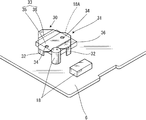
   The turntable 4 is configured to rotate by a rotational drive of a spindle motor 14 disposed at a substantially central portion of the frame 7, and is positioned above the turntable 4 and between the side wall portions 7 B of the frame 7. Further, a band plate-like support plate 15 is integrally constructed. A clamper 16 is fixed to the central portion of the support plate 15, and the disc 2 is rotated by sandwiching the disc 2 between the clamper 16 and the turntable 4. A circuit board 6 on which various electronic components 18 are mounted is disposed behind the support plate 15. The circuit board 6 is stretched over the upper surfaces of the left and right side wall portions 7B and fixed to the frame 7. The support plate 15 of the frame 7 has an L-shaped locking claw 20 for locking the circuit board 6. In addition to being integrally formed, positioning pins 21 and fixing holes 22 for fixing the circuit board 6 are formed in the side wall portions 7B and 7B of the frame 7. On the other hand, holes 23 and 23 are formed in the circuit board 6 at positions corresponding to the positioning pins 21 and the fixing holes 22, respectively, and the positioning pins are engaged with the front end portions of the circuit board 6 engaged with the locking claws 20. The circuit board 6 is fixed to the frame 7 by fitting 21 into one hole 23 and screwing a fixing screw 25 inserted into the other hole 23 into the fixing hole 22. Here, the circuit board 6 is fixed between the side wall portions 7B and 7B of the frame 7 so that the electronic component 18 mounted on the circuit board 6 faces the disk 2 side, that is, the inner surface side. The circuit board 6 fixed between the side wall parts 7B and 7B covers the open upper surface of the frame 7 so that the space part 27 surrounded by the circuit board 6 and the side wall part 7B of the frame 7 when the disk 2 is stored. The space 27 forms an air passage 28 through which air generated by the rotation of the disk 2 flows. A flat cable 18B is collectively connected to one side of the circuit board 6 fixed to the frame 7 via a connector 18C, and the flat cable 18B is electrically connected to the mechanical unit 14 and the like. Yes. Of the electronic components 18 mounted on the circuit board 6, the heat generating electronic components 18A such as a driver IC for driving various motors and an LSI for performing various controls have excellent heat conduction so as to cover them. A heat radiating plate 30 made of a thin metal plate is provided. The heat radiating plate 30 has a flat plate portion 31 that is formed in a rectangular shape when viewed from above and four leg portions 32 that are suspended from each corner portion of the flat plate portion 31. Each leg 32 is fixed to the circuit board 6 by appropriate means such as soldering so as to cover the component 18A. Further, the flat plate portion 31 is formed with a step recess 33 that is recessed toward the heat generating electronic component 18A. The step recess 33 is composed of a face plate portion 35 having a pair of vent holes 34 and tapered inclined surfaces 36, 36 provided on both sides of the face plate portion 35. By forming the stepped recess 33 having the inclined surfaces 36 and 36 in the flat plate portion 31 to be formed into a concavo-convex shape, the heat dissipation area of the heat radiating plate 30 is expanded to increase the heat dissipation efficiency.

上記にように構成される本実施例は、回路基板6を側壁部7B,7B間に固定し、この回路基板6によって、フレーム7の上面開放部分を覆うことによって、回路基板6とフレーム7の側壁部7Bによって囲まれた空間部27が形成され、この空間部27によって前記ディスク2の回転より生じる空気が流れる通風路28が形成される。そして、この通風路28に臨むように、回路基板6に実装した電子部品18,18Aをディスク2側に向けてフレーム7に固定することよって、前記ディスク2の回転より空気の流れが生じ、この空気の流れを利用して回路基板6に実装された発熱電子部品18Aからの熱を外部に放熱することができる。したがって、電子部品18,18Aから発散する熱が回路基板6とフレーム7の側壁部7Bによって囲まれた空間部27に篭らず、フレーム7の外部に抜け、回路基板6に実装した電子部品18,18Aを効率的に放熱することが可能となる。さらに、各種モータ等を駆動するドライバーICや諸制御を行うLSIなどの発熱電子部品18Aには、これを覆う放熱板30が回路基板6に固定され、この放熱板30は、その放熱面積を拡大するように、発熱電子部品18Aを覆う平板部31に傾斜面36,36を有する段差凹部33が形成されているため、発熱電子部品18Aが発散する熱が放熱板30へと効率的に伝わる。加えて、放熱板30の段差凹部33には一対の通気孔34が形成されているため、前述したディスク2の回転より生じる空気が通気孔34を通って発熱電子部品18Aの周囲を通過して流れることから放熱板30に伝わる発熱電子部品18Aの熱を効率良く放熱することができる。   In the present embodiment configured as described above, the circuit board 6 is fixed between the side wall portions 7B and 7B, and the circuit board 6 covers the open top surface of the frame 7 so that the circuit board 6 and the frame 7 are covered. A space portion 27 surrounded by the side wall portion 7B is formed, and an air passage 28 through which air generated by the rotation of the disk 2 flows is formed by the space portion 27. The electronic components 18 and 18A mounted on the circuit board 6 are fixed to the frame 7 so as to face the ventilation path 28, so that an air flow is generated by the rotation of the disk 2. The heat from the heat generating electronic component 18A mounted on the circuit board 6 can be radiated to the outside using the air flow. Therefore, the heat dissipated from the electronic components 18 and 18A does not enter the space portion 27 surrounded by the circuit board 6 and the side wall portion 7B of the frame 7, but escapes to the outside of the frame 7 and is mounted on the circuit board 6. , 18A can be efficiently radiated. Furthermore, a heat dissipation electronic component 18A such as a driver IC for driving various motors or an LSI for performing various controls is fixed to the circuit board 6 so as to cover the heat dissipation electronic component 18A. As described above, since the stepped concave portion 33 having the inclined surfaces 36 and 36 is formed in the flat plate portion 31 covering the heat generating electronic component 18A, the heat dissipated by the heat generating electronic component 18A is efficiently transmitted to the heat radiating plate 30. In addition, since a pair of vent holes 34 is formed in the stepped recess 33 of the heat sink 30, the air generated by the rotation of the disk 2 passes through the vent hole 34 and around the heat generating electronic component 18 </ b> A. Since it flows, the heat of the heat generating electronic component 18A transmitted to the heat radiating plate 30 can be efficiently radiated.

以上のように、本実施例においては、回路基板6をフレーム7の上面開口部を塞ぐことによって、ディスク2の回転よる空気が流れる通風路28が形成され、この通風路28に臨むように回路基板6に実装する電子部品18,18Aをディスク2側に向けて固定し、さらに、回路基板6に熱伝導性に優れた放熱板30が発熱電子部品18Aを近接するように固定することにより、発熱電子部品18Aからの熱を放熱板30に効果的に伝熱させ、さらに、通風路28を流れる前記ディスク2の回転よる空気が流れによって、発熱電子部品18A及び放熱板30から発散する熱をフレーム7の外部に効果的に発散させることができる。これにより、電子部品18,18Aから発散する熱が回路基板6とフレーム7の側壁部7Bによって囲まれた空間部27に篭らず、フレーム7の外部へと効率的に抜け、回路基板6に実装した電子部品18,18Aを効率的に放熱することができ、熱による発熱電子部品18Aの劣化を防止することができる。さらに、放熱板30は、発熱電子部品18Aを覆う平板部31に傾斜面36,36を有する段差凹部33を形成することによって、放熱面積が拡大し、発熱電子部品18Aが発散する熱が放熱板30へと効率的に伝わり、この発熱電子部品18Aの熱を効率的に放熱することができる。しかも、放熱板30の段差凹部33には一対の通気孔34が形成され、ディスク2の回転時に流れる空気が通気孔34を通って発熱電子部品18Aの周囲を流れることから、ディスク回転による気流を利用した放熱手段と発熱電子部品18Aに近接する放熱板30による放熱手段との相乗効果によって放熱板30に伝わる発熱電子部品18Aを効率良く放熱することができる。また、ディスク2の回転によって空気が流れる通風路28は、ディスク装置1の構成上、必要不可欠な回路基板6をフレーム7に固定して形成されているから、新たに放熱部品を用いる必要もないため、組付部品点数も低減され、その組付作業を簡略化できる。さらに、回路基板6は単にフレーム7の上面に固定されているだけなので、構造も簡単にあり、かつ、ディスク装置1全体の高さ寸法の抑えることが可能であり、ディスク装置1のコンパクト化に薄型化することができる。また、回路基板6は、フレーム7の側壁部7Bの上面に掛け渡して固定されているから、フレーム7が回路基板6によって補強され、フレーム7の剛性を高めることができ、さらに、回路基板6を取り外すことによってディスク装置1の上面部が開放状態となるため、ディスク装置1内部に備えられる部品の交換なども、容易に行うことができ、作業工程・時間の大幅な短縮化が図られる、という付随的な効果もある。   As described above, in this embodiment, the circuit board 6 is closed by the upper surface opening of the frame 7, thereby forming the air passage 28 through which the air due to the rotation of the disk 2 flows, and the circuit so as to face the air passage 28. By fixing the electronic components 18 and 18A mounted on the substrate 6 toward the disk 2 side, and further fixing the heat-radiating electronic component 18A close to the circuit board 6 by the heat dissipation plate 30 having excellent thermal conductivity, Heat from the heat generating electronic component 18A is effectively transferred to the heat radiating plate 30, and further, heat generated from the heat generating electronic component 18A and the heat radiating plate 30 is generated by the flow of the air of the disk 2 flowing through the ventilation path 28. It is possible to effectively diverge outside the frame 7. As a result, the heat dissipated from the electronic components 18, 18 </ b> A does not enter the space 27 surrounded by the circuit board 6 and the side wall 7 </ b> B of the frame 7, but efficiently escapes to the outside of the frame 7. The mounted electronic components 18 and 18A can be efficiently radiated, and deterioration of the heat generating electronic component 18A due to heat can be prevented. Further, the heat radiating plate 30 is formed with the stepped recess 33 having the inclined surfaces 36 and 36 in the flat plate portion 31 covering the heat generating electronic component 18A, so that the heat radiating area is expanded and the heat radiated from the heat generating electronic component 18A is dissipated. Thus, the heat of the heat generating electronic component 18A can be efficiently radiated. In addition, a pair of vent holes 34 are formed in the stepped recess 33 of the heat radiating plate 30, and the air flowing when the disk 2 rotates passes through the vent holes 34 around the heat generating electronic component 18 </ b> A. The heat generating electronic component 18A transmitted to the heat radiating plate 30 can be efficiently radiated by the synergistic effect of the used heat radiating device and the heat radiating means by the heat radiating plate 30 adjacent to the heat generating electronic component 18A. Further, the air passage 28 through which the air flows by the rotation of the disk 2 is formed by fixing the circuit board 6 which is indispensable in the configuration of the disk device 1 to the frame 7, so that it is not necessary to use a new heat radiation component. Therefore, the number of parts to be assembled is also reduced, and the assembling work can be simplified. Furthermore, since the circuit board 6 is simply fixed to the upper surface of the frame 7, the structure is simple, and the overall height of the disk device 1 can be suppressed, so that the disk device 1 can be made compact. Thinning can be achieved. Further, since the circuit board 6 is fixed over the upper surface of the side wall portion 7B of the frame 7, the frame 7 is reinforced by the circuit board 6, and the rigidity of the frame 7 can be increased. Since the upper surface portion of the disk device 1 is opened by removing the disk, it is possible to easily replace components provided in the disk device 1 and to greatly shorten the work process and time. There is also an accompanying effect.

以上、本発明の一実施例を詳述したが、本発明は前記実施例に限定されるものでなく、本発明の要旨の範囲内で種々の変形実施が可能である。例えば、回路基板6の取付構造やディスク装置の基本的構成は前記実施例に限定されるものではなく、適宜選定すればよい。さらに、本実施例では、トレイタイプのディスク装置について説明したが、搬入ローラーによりディスクを装置内へ挿入するスロットインタイプのディスク装置や、複数のディスクを装置内に収納可能なチェンジャータイプのディスク装置など各種のディスク装置に適用可能である。   As mentioned above, although one Example of this invention was explained in full detail, this invention is not limited to the said Example, A various deformation | transformation implementation is possible within the range of the summary of this invention. For example, the mounting structure of the circuit board 6 and the basic configuration of the disk device are not limited to the above embodiment, and may be selected as appropriate. Furthermore, in the present embodiment, the tray type disk device has been described. However, a slot-in type disk device in which a disk is inserted into the device by a carry-in roller, and a changer type disk device that can store a plurality of disks in the device. It can be applied to various disk devices.

本発明の一実施例を示すディスク装置の斜視図である。1 is a perspective view of a disk device showing an embodiment of the present invention. 同上、回路基板をフレームから取り外した状態を示すディスク装置の斜視図である。FIG. 3 is a perspective view of the disk device showing a state where the circuit board is removed from the frame. 同上、回路基板とフレームを分解した状態を示すディスク装置の斜視図である。FIG. 2 is a perspective view of the disk device showing a state where the circuit board and the frame are disassembled. 同上、回路基板がない状態を示すディスク装置の平面図である。It is a top view of the disc apparatus which shows a state without a circuit board same as the above. 図1のA−A線断面図である。It is the sectional view on the AA line of FIG. 図1のB−B線断面図である。It is the BB sectional view taken on the line of FIG. 図6における放熱板廻りの拡大断面図である。It is an expanded sectional view around the heat sink in FIG. 放熱板の取り付け状態を示す斜視図である。It is a perspective view which shows the attachment state of a heat sink.

符号の説明Explanation of symbols

1 ディスク装置
2 ディスク
3 トレイ
4 ターンテーブル
5 ピックアップレンズ
6 回路基板
7 フレーム
7B 側壁部
16 クランパ
18 電子部品
18A 発熱電子部品
27 空間部
28 通風路
30 放熱板
31 平板部
33 段差凹部
34 通気孔
36 傾斜面
DESCRIPTION OF SYMBOLS 1 Disc apparatus 2 Disc 3 Tray 4 Turntable 5 Pickup lens 6 Circuit board 7 Frame 7B Side wall part 16 Clamper 18 Electronic component 18A Heating electronic component 27 Space part 28 Ventilation path 30 Heat sink 31 Flat plate part 33 Step recessed part 34 Vent hole 36 Inclination surface

Claims (3)

ディスクを搬入/搬出するトレイと、前記ディスクを回転駆動するターンテーブルと、前記ディスクの記録面にレーザー光を照射して前記ディスクの記録/再生を行うピックアップレンズと、ディスク装置を制御する回路基板と、これら構成部品を組付けるフレームとを備えたディスク装置であって、前記フレームは、対向する一対の側壁部を備え、この側壁部の上面に前記回路基板を掛け渡して該側壁部と前記回路基板とで囲まれた空間部に前記ディスクの回転時に発生する空気が流れる通風路を形成するとともに、この通風路に臨ませるように、前記回路基板の実装面を前記ディスク側に向けて取り付けたことを特徴とする放熱効果を高めたディスク装置。   A tray for loading / unloading a disk, a turntable for rotating the disk, a pickup lens for recording / reproducing the disk by irradiating a recording surface of the disk, and a circuit board for controlling the disk device And a frame for assembling these components, wherein the frame includes a pair of opposing side wall portions, and the circuit board is stretched over the upper surface of the side wall portions and the side wall portions and the disk device. A ventilation path through which air generated when the disk rotates is formed in a space surrounded by the circuit board, and the mounting surface of the circuit board is attached to the disk side so as to face the ventilation path. A disk device with improved heat dissipation effect. 前記回路基板に実装する電子部品に近接させて放熱板を設けるとともに、この放熱板には、前記電子部品を覆う平板部と、前記回路基板に固定する脚部を備えるとともに、前記平板部に傾斜面を備えた段差凹部を形成したことを特徴とする請求項1記載の放熱効果を高めたディスク装置。   A heat sink is provided close to the electronic component mounted on the circuit board. The heat sink includes a flat plate portion that covers the electronic component and a leg portion that is fixed to the circuit board, and is inclined to the flat plate portion. 2. The disk device with improved heat dissipation effect according to claim 1, wherein a stepped recess having a surface is formed. 前記段差凹部に複数の通気孔を設けたことを特徴とする請求項2記載の放熱効果を高めたディスク装置。   3. The disk device with an improved heat dissipation effect according to claim 2, wherein a plurality of air holes are provided in the step recess.
JP2004069233A 2004-03-11 2004-03-11 Disk device increasing heat radiating effect Withdrawn JP2005259256A (en)

Priority Applications (1)

Application Number Priority Date Filing Date Title
JP2004069233A JP2005259256A (en) 2004-03-11 2004-03-11 Disk device increasing heat radiating effect

Applications Claiming Priority (1)

Application Number Priority Date Filing Date Title
JP2004069233A JP2005259256A (en) 2004-03-11 2004-03-11 Disk device increasing heat radiating effect

Publications (2)

Publication Number Publication Date
JP2005259256A true JP2005259256A (en) 2005-09-22
JP2005259256A5 JP2005259256A5 (en) 2006-08-10

Family

ID=35084817

Family Applications (1)

Application Number Title Priority Date Filing Date
JP2004069233A Withdrawn JP2005259256A (en) 2004-03-11 2004-03-11 Disk device increasing heat radiating effect

Country Status (1)

Country Link
JP (1) JP2005259256A (en)

Similar Documents

Publication Publication Date Title
JP2006323955A (en) Optical disk device
JP4908883B2 (en) Optical disk device
JP2007188599A (en) Electronic device
JP4272091B2 (en) Disk unit with enhanced heat dissipation effect
JP2003085964A (en) Optical disk device
JP2008186501A (en) Optical disk device
JP2004310883A (en) Optical disk device
JP2005259256A (en) Disk device increasing heat radiating effect
TWI286742B (en) Recording disk apparatus
JP4843341B2 (en) Optical disk device
JP2005158219A (en) Disk drive
JP2008276862A (en) Optical disk device
JP2008016067A (en) Optical disk device
US20070150909A1 (en) Disc drive
JP2007257724A (en) Disk driving device
JP2008033998A (en) Disk device equipped with cooling mechanism
JP2698210B2 (en) Optical disk drive
JP2007157261A (en) Optical disk drive unit
JP2006040376A (en) Heat radiation apparatus of electronic equipment for disk, and heat radiation method of electronic equipment for disk
JP4246685B2 (en) Optical pickup device
JP2003157669A (en) Casing structure of audio equipment
JP2008028266A (en) Electronic apparatus
JP4403933B2 (en) Optical disk device
JP2007004894A (en) Electronic device
JP2003249067A (en) Optical disk drive

Legal Events

Date Code Title Description
A521 Written amendment

Free format text: JAPANESE INTERMEDIATE CODE: A523

Effective date: 20060623

A621 Written request for application examination

Free format text: JAPANESE INTERMEDIATE CODE: A621

Effective date: 20060623

A761 Written withdrawal of application

Effective date: 20070322

Free format text: JAPANESE INTERMEDIATE CODE: A761