JP2005256985A - Hose band - Google Patents

Hose band Download PDF

Info

Publication number
JP2005256985A
JP2005256985A JP2004070527A JP2004070527A JP2005256985A JP 2005256985 A JP2005256985 A JP 2005256985A JP 2004070527 A JP2004070527 A JP 2004070527A JP 2004070527 A JP2004070527 A JP 2004070527A JP 2005256985 A JP2005256985 A JP 2005256985A
Authority
JP
Japan
Prior art keywords
latching
receiving
hose band
belt
plate
Prior art date
Legal status (The legal status is an assumption and is not a legal conclusion. Google has not performed a legal analysis and makes no representation as to the accuracy of the status listed.)
Pending
Application number
JP2004070527A
Other languages
Japanese (ja)
Other versions
JP2005256985A5 (en
Inventor
Kazuo Shimura
一夫 志村
Current Assignee (The listed assignees may be inaccurate. Google has not performed a legal analysis and makes no representation or warranty as to the accuracy of the list.)
OGINO KENKO KK
Original Assignee
OGINO KENKO KK
Priority date (The priority date is an assumption and is not a legal conclusion. Google has not performed a legal analysis and makes no representation as to the accuracy of the date listed.)
Filing date
Publication date
Application filed by OGINO KENKO KK filed Critical OGINO KENKO KK
Priority to JP2004070527A priority Critical patent/JP2005256985A/en
Publication of JP2005256985A publication Critical patent/JP2005256985A/en
Publication of JP2005256985A5 publication Critical patent/JP2005256985A5/ja
Pending legal-status Critical Current

Links

Images

Abstract

<P>PROBLEM TO BE SOLVED: To provide a hose band having a diameter to be widely applied and easy to be changed. <P>SOLUTION: This hose band is provided with a belt-like member 1, and a lock member 2 and a lock-receiver member 3 respectively fitted to the belt-like member 1 and to be engaged with each other. At least one part of the lock member 2 is structured of a spring member 4, and length L from a fitting part B fitted to the belt-like member 1 to an engagement part A with the lock-receiver member 3 is formed possible to be extended/shrunken. Furthermore, the lock-receiver member 3 is formed with an insert hole 3A, into which the belt-like member 1 is to be inserted, and the belt-like member 1A passed through the insert hole 3a is folded to fit the lock-receiver member 3 to the belt-like member 1. <P>COPYRIGHT: (C)2005,JPO&NCIPI

Description

本発明は、ホースバンドに関するものである。より詳しくは、例えば、製造工場や食品加工工場等においてパイプにホースを接続する場合や、電柱に配線をくくり付ける場合、更には荷物をくくり付ける場合などに使用することができるホースバンドに関するものである。   The present invention relates to a hose band. More specifically, it relates to a hose band that can be used when connecting a hose to a pipe in a manufacturing factory, a food processing factory, etc., attaching a wire to an electric pole, and further attaching a load. is there.

この種のホースバンドとしては、適宜加工の施された可撓性を有する環状の帯状部材からなるものや、帯状部材に縮径を図るためのウォームを備えたものなどがある(例えば、特許文献1、特許文献2参照)。   Examples of this type of hose band include a flexible belt-shaped member that has been appropriately processed, and a belt-shaped member provided with a worm for reducing the diameter (for example, Patent Documents). 1, see Patent Document 2).

しかしながら、これら従来のホースバンドは、適用範囲径が狭く、また、径の変更に手間がかかる。適用範囲径が狭いと、例えば、同一工場内においてもパイプやホースなどの径はさまざまであるから、適用箇所に応じて複数種のホースバンドを使い分けなければならなくなる。複数種のホースバンドの使い分けは、作業効率の面で好ましくないだけではなく、ホースバンド自体の製造コスト増加にもつながる。また、径の変更に手間がかかると、作業効率が悪くなるだけではなく、パイプやホースなどの締め付けが不完全になる原因ともなる。
特開平10−318473号公報 特開2002−295757号公報
However, these conventional hose bands have a narrow application range diameter, and it takes time to change the diameter. If the applicable range diameter is narrow, for example, pipes and hoses have various diameters even in the same factory, and therefore, a plurality of types of hose bands must be used properly according to the application location. The use of multiple types of hose bands is not only undesirable in terms of work efficiency, but also leads to an increase in the manufacturing cost of the hose bands themselves. In addition, if the change of the diameter is troublesome, not only the work efficiency is deteriorated, but also the cause of incomplete tightening of the pipe, the hose and the like is caused.
JP 10-318473 A JP 2002-295757 A

本発明が解決しようとする主たる課題は、適用範囲径が広く、しかも径の変更が容易なホースバンドとすることにある。   The main problem to be solved by the present invention is to provide a hose band having a wide applicable range diameter and easy diameter change.

この課題を解決した本発明は、次のとおりである。
〔請求項1記載の発明〕
帯状部材と、この帯状部材に取り付けられ相互に掛合する掛止部材及び受け掛止部材と、が備わるホースバンドであって、
前記掛止部材は、その少なくとも一部がばね部材で構成されたことによって前記帯状部材との取付部から前記受け掛止部材との掛合部までの長さが伸縮可能とされ、
前記受け掛止部材は、前記帯状部材が挿通される挿通孔を有し、この挿通孔を通された帯状部材が折り返されることによって、前記受け掛止部材が前記帯状部材に取り付けられる、ことを特徴とするホースバンド。
The present invention that has solved this problem is as follows.
[Invention of Claim 1]
A hose band provided with a belt-like member, a hook member attached to the belt-like member and engaged with each other, and a receiving hook member,
As for the said latching member, the length from the attachment part with the said strip | belt-shaped member to the latching part with the said receiving latching member can be expanded-contracted because at least one part was comprised with the spring member,
The receiving latching member has an insertion hole through which the strip member is inserted, and the receiving latch member is attached to the strip member by folding the strip member passed through the insertion hole. Characteristic hose band.

〔請求項2記載の発明〕
掛止部材が、帯状部材に取り付けられる基材と、この基材に軸支されたレバー材と、このレバー材の軸部よりも基端側に直接又はフック部材を介して取り付けられたばね部材と、を有し、
前記基材に受け係止部が設けられ、かつ前記レバー材に係止部が設けられ、前記レバー材を回動して前記基材に沿わせると、前記係止部及び前記受け係止部が係合する、請求項1記載のホースバンド。
[Invention of Claim 2]
A base member attached to the belt-like member, a lever member pivotally supported by the base member, and a spring member attached to the base end side of the lever member directly or via a hook member; Have
A receiving latching portion is provided on the base material, and a latching portion is provided on the lever material, and when the lever material is rotated along the base material, the latching portion and the receiving latching portion are provided. The hose band of claim 1, which engages.

〔請求項3記載の発明〕
掛止部材の基材先端部に受け掛止部材側に延在する延在片が設けられ、前記掛止部材及び前記受け掛止部材を掛合すると、前記延在片が前記受け掛止部材を上から押さえ付ける、請求項2記載のホースバンド。
[Invention of Claim 3]
An extending piece that extends toward the receiving latching member is provided at the tip of the base member of the latching member. When the latching member and the receiving latching member are engaged with each other, the extending piece causes the receiving latching member to The hose band according to claim 2, wherein the hose band is pressed from above.

〔請求項4記載の発明〕
レバー材の両側壁にそれぞれ貫通孔が形成され、
フック部材が、前記貫通孔にそれぞれ側方から貫通する貫通針を有し、この貫通針は、先割り可能とされている、請求項2又は請求項3記載のホースバンド。
[Invention of Claim 4]
Through holes are formed on both side walls of the lever material,
The hose band according to claim 2 or 3, wherein the hook member has penetrating needles penetrating from the side into the through-holes, and the penetrating needles can be preliminarily split.

〔請求項5記載の発明〕
受け掛止部材が、帯状部材の長手方向に沿う底板及びこの底板の両側縁からそれぞれ上方に延在する側板で断面略コ字状とされ、
前記両側板は、それぞれ前記長手方向に関して異なる複数の位置に切り欠き部が形成され、一方の側板の切り欠き部及びこれに対応する他方の側板の切り欠き部でそれぞれ受け掛合部が構成されている、請求項1〜4のいずれかに記載のホースバンド。
[Invention of Claim 5]
The receiving and latching member has a substantially U-shaped cross section with a bottom plate along the longitudinal direction of the belt-like member and side plates extending upward from both side edges of the bottom plate,
The side plates are each formed with a notch portion at a plurality of different positions in the longitudinal direction, and a notch portion of one side plate and a notch portion of the other side plate corresponding to the notch portion constitute a receiving engagement portion. The hose band according to any one of claims 1 to 4.

〔請求項6記載の発明〕
掛止部材の先端部が、一方の側板の切り欠き部及びこれに対応する他方の側板の切り欠き部に差し込まれて掛合する板材で構成されている、請求項5記載のホースバンド。
[Invention of Claim 6]
The hose band according to claim 5, wherein the front end portion of the latching member is constituted by a plate member that is inserted into and engaged with a cutout portion of one side plate and a cutout portion of the other side plate corresponding thereto.

〔請求項7記載の発明〕
板材の基端部に、掛合状態において側板の表面に沿う掛止片が設けられている、請求項6記載のホースバンド。
[Invention of Claim 7]
The hose band according to claim 6, wherein a latching piece along the surface of the side plate in the engaged state is provided at the base end portion of the plate material.

〔請求項8記載の発明〕
板材及びフック部材の少なくとも一方に、ばね部材の先端部又は基端部が引っ掛かる切り欠き部が形成され、この切り欠き部の開口縁に突片が設けられ、この突片を折り曲げると前記切り欠き部の開口が閉じる、請求項6又は請求項7記載のホースバンド。
[Invention of Claim 8]
At least one of the plate member and the hook member is formed with a notch portion on which the distal end portion or the base end portion of the spring member is hooked, and a projecting piece is provided at the opening edge of the notch portion, and when the projecting piece is bent, the notch The hose band according to claim 6 or 7, wherein the opening of the portion is closed.

本発明によると、ホースバンドの適用範囲径が広くなり、また、ホースバンド径の変更が容易となる。   According to the present invention, the applicable range diameter of the hose band is widened, and the change of the hose band diameter is facilitated.

以下、本発明の実施の形態を説明する。
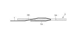
図1に示すように、本実施の形態のホースバンド10は、帯状部材1と、この帯状部材1に取り付けられ相互に掛合する掛止部材2及び受け掛止部材3と、から主になる。
帯状部材1の素材は、特に限定されず、例えば、SUS、アルミ、スチール等の可撓性を有する素材や、ナイロン、板紙、ビニール、ポリエステル、ポリプロピレンなどの公知の素材を使用することができる。用途に応じて、例えば、耐久性や防錆性などが要求される製造工場や食品加工工場等における使用であれば、SUSを、柔軟性や客体の毀損防止などが要求される荷造りにおける使用であれば、ナイロンやポリプロピレンなどを、用いるとよい。
Embodiments of the present invention will be described below.
As shown in FIG. 1, the hose band 10 of the present embodiment is mainly composed of a band-shaped member 1, a hooking member 2 attached to the band-shaped member 1, and a hooking member 3 that are engaged with each other.
The material of the belt-shaped member 1 is not particularly limited, and for example, a flexible material such as SUS, aluminum, or steel, or a known material such as nylon, paperboard, vinyl, polyester, or polypropylene can be used. Depending on the application, for example, SUS can be used in packaging where flexibility and prevention of damage to the object are required for use in manufacturing factories and food processing factories where durability and rust prevention are required. If present, nylon or polypropylene may be used.

本実施の形態の掛止部材2は、その一部がコイルばね等のばね部材4で構成されており、帯状部材1との取付部Bから受け掛止部材3との掛合部Aまでの長さLが伸縮可能とされている。このばね部材4の伸縮によって、ホースバンド10の径は、自動的に微調節(変更)される。この微調節は、ばね部材4の伸縮強度に比例することになるので、ホースバンド10の用途に応じた伸縮強度のばね部材を使用するとよい。   A part of the latching member 2 of the present embodiment is constituted by a spring member 4 such as a coil spring, and the length from the attaching part B with the belt-like member 1 to the engaging part A with the receiving latching member 3. The length L is extendable. As the spring member 4 expands and contracts, the diameter of the hose band 10 is automatically finely adjusted (changed). Since this fine adjustment is proportional to the expansion / contraction strength of the spring member 4, a spring member having an expansion / contraction strength corresponding to the application of the hose band 10 may be used.

本実施の形態のばね部材4は、図12の(a)及び(b)に示すように、その基端部4A及び先端部4Bの巻き方向がほぼ垂直(ばね部材4の延在方向)に変化しており、後述するレバー材7若しくはフック部材8に引っ掛けることができ、又は受け掛止部材3若しくは後述する板材9に引っ掛けることができる、ようになっている。ただし、これは、本実施の形態では、掛止部材2の一部がばね部材で構成されるようにしたためであり、掛止部材2の全部をばね部材で構成する形態、つまり、ばね部材4の基端部4Aを直接帯状部材1に取り付け、ばね部材4の先端部4Bを直接受け掛止部材3と掛合させる形態、とすることもできる。   In the spring member 4 of the present embodiment, as shown in FIGS. 12A and 12B, the winding direction of the base end portion 4A and the tip end portion 4B is substantially vertical (the extending direction of the spring member 4). It has changed, and can be hooked on a lever member 7 or a hook member 8 described later, or can be hooked on a receiving member 3 or a plate member 9 described later. However, this is because, in the present embodiment, a part of the latching member 2 is constituted by a spring member, and the whole latching member 2 is constituted by a spring member, that is, the spring member 4. The base end portion 4 </ b> A can be directly attached to the belt-like member 1, and the tip end portion 4 </ b> B of the spring member 4 can be directly engaged with the receiving latching member 3.

本実施の形態の受け掛止部材3は、図2〜4に示すように、帯状部材1の長手方向に沿う底板37及びこの底板37の両側縁からそれぞれ上方に延在する、本実施の形態では上方に折れ曲がる側板38,38で断面略コ字状(図4参照)に形成されている(なお、図2は、側板38,38を底板37に対してほぼ直角に折り曲げて断面略コ字状にする前の状態を示している。)。
底板37には、帯状部材1が挿通される挿通孔3Aが形成されており、図5に模式的に示すように、挿通孔3Aに帯状部材1が挿通され、挿通された帯状部材1Aが折り返されることによって、受け掛止部材3が帯状部材1に取り付けられるようになっている。このように本実施の形態のホースバンド10は、帯状部材1の折り返し位置を変化させることによってホースバンド径を変更するものなので、適用範囲径が大変広い。しかも、微調節(変更)は、ばね部材4によってなされるので、帯状部材1の折り返し位置を厳密に調節する必要がなく、径変更作業は、容易である。
As shown in FIGS. 2 to 4, the receiving member 3 of the present embodiment extends upward from the bottom plate 37 along the longitudinal direction of the belt-shaped member 1 and both side edges of the bottom plate 37. In FIG. 2, the side plates 38, 38 that are bent upward are formed in a substantially U-shaped cross section (see FIG. 4) (in FIG. 2, the side plates 38, 38 are bent at a substantially right angle with respect to the bottom plate 37). It shows the state before the shape.)
The bottom plate 37 is formed with an insertion hole 3A through which the band-shaped member 1 is inserted. As schematically shown in FIG. 5, the band-shaped member 1 is inserted into the insertion hole 3A, and the inserted band-shaped member 1A is folded back. Accordingly, the receiving member 3 is attached to the belt-like member 1. Thus, since the hose band 10 of this Embodiment changes a hose band diameter by changing the folding position of the strip | belt-shaped member 1, an application range diameter is very wide. Moreover, since the fine adjustment (change) is made by the spring member 4, it is not necessary to strictly adjust the folding position of the belt-like member 1, and the diameter changing operation is easy.

図5に示すように、本実施の形態では、挿通孔3Aの基端側に、挿通孔3Aに平行して第2の挿通孔3Bが形成されている。挿通孔3Aに帯状部材1を挿通するに先立って、この第2の挿通孔3Bに、帯状部材1を挿通しておくと、受け掛止部材3の帯状部材1に対する取り付けが強固で安定したものとなる。   As shown in FIG. 5, in the present embodiment, a second insertion hole 3B is formed on the base end side of the insertion hole 3A in parallel with the insertion hole 3A. Prior to inserting the band-shaped member 1 into the insertion hole 3A, the band-shaped member 1 is inserted into the second insertion hole 3B, so that the attachment of the receiving member 3 to the band-shaped member 1 is strong and stable. It becomes.

挿通孔3Aや挿通孔3Bの形状は、特に限定されず、帯状部材1を挿通することができるものであれば足りる。本実施の形態では、挿通孔3A及び挿通孔3Bともに、底板37幅方向に細長い略矩形状としている。   The shape of the insertion hole 3A and the insertion hole 3B is not particularly limited as long as the band-like member 1 can be inserted. In the present embodiment, both the insertion hole 3A and the insertion hole 3B have a substantially rectangular shape elongated in the width direction of the bottom plate 37.

一方、受け掛止部材3の側板38,38は、それぞれ長手方向に関して異なる複数の位置に、本実施の形態では4箇所に、それぞれ先端側斜め下方に向かう切り欠き部39,39…が形成されおり、一方の側板38の切り欠き部39及びこれに対応する他方の側板38の切り欠き部39で、それぞれ受け掛合部が構成されている。このように受け掛合部を複数設けることで、ばね部材4による微調節と帯状部材1の折り返しによる大幅な調節との間の中間的な径調節が可能となる。また、この径調節は、掛止部材2と受け掛止部材3とを掛合させる際に、利用する受け掛合部(39,39)を変えるのみで足りるので、容易である。   On the other hand, the side plates 38, 38 of the receiving member 3 are formed with notches 39, 39,. The notch 39 of one side plate 38 and the corresponding notch 39 of the other side plate 38 constitute a receiving engagement portion. By providing a plurality of receiving and engaging portions in this way, an intermediate diameter adjustment between the fine adjustment by the spring member 4 and the large adjustment by the folding back of the belt-like member 1 is possible. This diameter adjustment is easy because it is only necessary to change the receiving and engaging portions (39, 39) to be used when the engaging member 2 and the receiving member 3 are engaged.

本発明において、掛止部材2は、その一部がばね部材4で構成されており、受け掛止部材3と掛合するものであれば足りるが、本実施の形態においては、図1に示すように、帯状部材1に取り付けられる基材5(図6〜11参照)と、この基材5の例えば先端部に軸材6によって軸支されたレバー材7と、このレバー材7の軸部(6)よりも基端側に直接又は本実施の形態のようにフック部材8を介して取り付けられたばね部材4と、から主になる。この形態では、掛止部材2の先端側(受け掛止部材3側)を構成するばね部材4が直接又はフック部材8を介してレバー材7の軸部(6)よりも基端側に取り付けられているので、レバー材7を回動して基材5に沿わせると、掛止部材2の掛合部Aが基端側に引かれ、ホースバンド10の径が若干短くなる。したがって、本掛止部材2によると、レバー材7を回動させるという簡易な操作のみによって、パイプやホースなどの対象物の締め付けが完了する。   In the present invention, it is sufficient that the latch member 2 is partly composed of the spring member 4 and engages with the receiver latch member 3, but in the present embodiment, as shown in FIG. In addition, a base material 5 (see FIGS. 6 to 11) attached to the belt-shaped member 1, a lever material 7 pivotally supported by a shaft material 6 at, for example, a tip portion of the base material 5, and a shaft portion ( It is mainly composed of the spring member 4 attached to the proximal end side than 6) directly or via the hook member 8 as in the present embodiment. In this embodiment, the spring member 4 constituting the distal end side (the receiving latching member 3 side) of the latching member 2 is attached to the proximal end side than the shaft portion (6) of the lever member 7 directly or via the hook member 8. Therefore, when the lever member 7 is rotated and moved along the base member 5, the hooking portion A of the hooking member 2 is pulled to the base end side, and the diameter of the hose band 10 is slightly shortened. Therefore, according to the present latching member 2, the fastening of the object such as a pipe or a hose is completed only by a simple operation of rotating the lever member 7.

もっとも、以上によると操作は簡易となるものの、対象物から強い衝撃、振動を受けるなどすると、レバー材7が基材5から離れる方向に回動し、意図せずに締め付けが解除されてしまうおそれがある。そこで、本実施の形態では、図6〜11に示すように、基材5に受け係止部12が設けられ、かつレバー材7に係止部18が設けられ、レバー材7を回動して基材5に沿わせると、係止部18及び受け係止部12が係合するロック機構を備えている。このロック機構の具体的形状は、特に限定されるものではないが、本実施の形態の図11に示すロック機構を推奨する。
本ロック機構においては、まず、受け係止部12が、基材5(平板11)から上方に立ち上がり、その先端部12Aが適宜の角度、本実施の形態では約120〜160度折り返された形状となっている。他方、係止部18は、レバー材7の側壁19に貫通させられた可動板20と、この可動板20を切り欠いて形成した幅狭部22に嵌合され、可動板20の切り欠いていない部位24及び側壁19に挟み込まれたスプリングなどの伸縮部材23と、から主になる。
可動板20の切り欠いていない部位24は、図11の(1)に断面図及び平面図として示すように、係合前においては受け係止部12の先端部12Aに突き当たる位置に設けられている。また、この切り欠いていない部位24の先端側には、挿通部21(切り欠き)が形成されており、この挿通部21は、受け係止部12の先端部12Aよりも、可動板20の長手方向に関する長さが長くなっている。したがって、レバー材7を基材5に沿わせるために下方に回動させると、可動板20の切り欠いていない部位24が受け係止部12の先端部12Aに突き当たり、この先端部12Aは斜め下方を向いているので、可動板20は、伸縮部材23を縮めながら基端側(側壁19側)に徐々にスライドし、図11の(2)に示すように、挿通部21に受け係止部12が挿通されることになる。そして、更にレバー材7を下方に回動させ、可動板20の切り欠いていない部位24が受け係止部12の先端部12Aよりも下方となると、図11の(3)に示すように、縮まっている伸縮部材23が側壁19から受ける反発力によって、可動板20が先端側に押し返され、可動板20の切り欠いていない部位24が係止部12の先端部12Aの下方に戻ることになる。これにより、レバー材7が基材5から離れる方向に回動しようとしても切り欠いていない部位24が受け係止部12の先端部12Aに引っ掛かることになるので、レバー材7の基材5から離れる方向への回動が防止される。以上の係合は、レバー材7を回動して基材5に沿わせるという作業にともなって自動的に行われるので、作業が全く増えない。また、レバー材7を基材5から離れる方向に回動して締め付けを解除するにも、可動板20の先端部20Aを基端側に押しながら行うのみ足りるので、大変簡易である。
However, according to the above, although the operation is simple, when receiving a strong impact or vibration from the object, the lever material 7 may rotate in a direction away from the base material 5 and the tightening may be released unintentionally. There is. Therefore, in the present embodiment, as shown in FIGS. 6 to 11, the receiving lock 12 is provided on the base 5, and the lock 18 is provided on the lever member 7, and the lever 7 is rotated. Then, a locking mechanism is provided that engages the locking portion 18 and the receiving locking portion 12 along the base material 5. The specific shape of the lock mechanism is not particularly limited, but the lock mechanism shown in FIG. 11 of the present embodiment is recommended.
In the present locking mechanism, first, the receiving latching portion 12 rises upward from the base material 5 (flat plate 11), and its tip portion 12A is folded at an appropriate angle, in this embodiment, about 120 to 160 degrees. It has become. On the other hand, the locking portion 18 is fitted to a movable plate 20 that is penetrated through the side wall 19 of the lever member 7 and a narrow portion 22 formed by cutting out the movable plate 20. The main part is the extension member 23 such as a spring sandwiched between the non-part 24 and the side wall 19.
As shown in the sectional view and the plan view of FIG. 11 (1), the uncut portion 24 of the movable plate 20 is provided at a position where it abuts against the distal end portion 12A of the receiving locking portion 12 before the engagement. Yes. Further, an insertion portion 21 (notch) is formed on the distal end side of the portion 24 that is not notched, and the insertion portion 21 is located on the movable plate 20 more than the distal end portion 12 </ b> A of the receiving locking portion 12. The length in the longitudinal direction is long. Therefore, when the lever member 7 is rotated downward in order to follow the base material 5, the portion 24 of the movable plate 20 that is not cut out abuts on the front end portion 12 </ b> A of the receiving locking portion 12, and the front end portion 12 </ b> A is inclined. Since it faces downward, the movable plate 20 gradually slides to the base end side (side wall 19 side) while shrinking the expansion and contraction member 23, and is received and locked to the insertion portion 21 as shown in FIG. The part 12 is inserted. Then, the lever member 7 is further rotated downward, and when the notched portion 24 of the movable plate 20 is below the front end portion 12A of the receiving latching portion 12, as shown in FIG. The movable plate 20 is pushed back to the distal end side by the repulsive force that the contracted elastic member 23 receives from the side wall 19, and the notched portion 24 of the movable plate 20 returns below the distal end portion 12 </ b> A of the locking portion 12. become. Thereby, even if the lever material 7 tries to rotate in a direction away from the base material 5, the portion 24 not cut out is caught by the tip end portion 12 </ b> A of the receiving locking portion 12. Rotation in the direction of leaving is prevented. The above engagement is automatically performed along with the operation of rotating the lever member 7 along the base material 5, so that the operation does not increase at all. Further, the lever member 7 can be rotated away from the base member 5 to release the tightening, since it is only necessary to push the distal end portion 20A of the movable plate 20 toward the proximal end side, which is very simple.

本実施の形態において、基材5は、図6及び図7に示すように、基端部が若干幅広の平板11と、この平板11の先端部両側縁から上方に延在し、レバー材7を軸支するための軸材6が挿通される軸孔14が形成された立ち上がり片13,13と、平板11幅広部の先端側に形成された括れ部15から立ち上がる前述した受け係止部12と、から主になる。
基材5の帯状部材1に対する取り付け方法は、特に限定されず、例えば、図6及び図7に示すように、平板11の裏面11bに帯状部材1を溶接、接着、ビス止め、リベット止めするなどして取り付ける方法や、図8及び図9に示すように、平板11の表面11aに括れ部15に沿うように切り欠き16が形成された帯状部材1を溶接、接着、ビス止め、リベット止めするなどして取り付ける方法などを、例示することができる。
In the present embodiment, as shown in FIGS. 6 and 7, the base material 5 includes a flat plate 11 having a slightly wide base end portion, and extends upward from both side edges of the distal end portion of the flat plate 11. The above-described receiving and locking portions 12 rising from the rising pieces 13 and 13 formed with shaft holes 14 through which the shaft member 6 for supporting the shaft is inserted and the constricted portion 15 formed on the distal end side of the wide portion of the flat plate 11 are formed. And from the main.
The method for attaching the base material 5 to the belt-like member 1 is not particularly limited. For example, as shown in FIGS. 6 and 7, the belt-like member 1 is welded, bonded, screwed, riveted to the back surface 11 b of the flat plate 11. 8 and 9, the belt-like member 1 in which the notch 16 is formed along the constricted portion 15 on the surface 11a of the flat plate 11 is welded, bonded, screwed, and riveted. For example, the attachment method can be exemplified.

ただし、図10に示すように、基材5の先端部よりも受け掛止部材3側において帯状部材1を折り返し、この折り返し縁と基材5先端部との間に帯状部材1で形成された延在片17が設けられるようにするのが好ましい。これにより、掛止部材2と受け掛止部材3との掛合時に、延在片17が受け掛止部材3を、本実施の形態においては底板37を、上から押さえ付けることになるので、掛止部材2と受け掛止部材3との一体性が向上する。この場合、平板11の表面11a及び裏面11bと帯状部材1とは、溶接や、接着、ビス止め、リベット止めすることもできるが、単に帯状部材1とその先端部1Bとで平板11を挟み込むだけの状態としておくことでも足りる。   However, as shown in FIG. 10, the band-shaped member 1 is folded back on the receiving member 3 side with respect to the front end portion of the base material 5, and the band-shaped member 1 is formed between the folded edge and the front end portion of the base material 5. It is preferable that the extending piece 17 is provided. Thus, when the latching member 2 and the latching member 3 are engaged with each other, the extending piece 17 presses the latching member 3 and, in the present embodiment, the bottom plate 37 from above. The integrity of the stop member 2 and the catch member 3 is improved. In this case, the front surface 11a and the back surface 11b of the flat plate 11 and the belt-like member 1 can be welded, bonded, screwed, or riveted, but the flat plate 11 is simply sandwiched between the belt-like member 1 and its tip 1B. It is enough to keep it in the state of.

本実施の形態においては、帯状部材1を受け掛止部材3側において折り返すことによって、基材5の先端部に受け掛止部材3側に延在する延在片17が設けられる形態としたが、これに限定する趣旨ではない。例えば、平板11を受け掛止部材3側に延在させ、この延在部を延在片17とすることもできる。   In the present embodiment, the strip-shaped member 1 is folded back on the receiving member 3 side, whereby the extending piece 17 extending to the receiving member 3 side is provided at the tip of the base material 5. It is not intended to limit this. For example, the flat plate 11 can be extended to the side of the retaining member 3, and the extended portion can be used as the extended piece 17.

以上のように、延在片17を設ける場合は、図3に示すように、受け掛止部材3の底板37に、先端側を基端側より低くするための段差部40を設けるのが好ましい。基端側が低くなっていると、この低くなっている部位に延在片17が収まることになるので、ホースバンド10の表面が平滑化する。また、段差部40に、例えば、先述した挿通孔3Aや3Bと同一形状の挿通孔3Cを設け、この挿通孔3Cに延在片17の先端部が挿通するようにすると、掛止部材2と受け掛止部材3との一体性がより向上する。   As described above, when the extending piece 17 is provided, as shown in FIG. 3, it is preferable to provide a stepped portion 40 for lowering the distal end side from the proximal end side on the bottom plate 37 of the receiving member 3. . When the base end side is lowered, the extended piece 17 is accommodated in the lowered portion, so that the surface of the hose band 10 is smoothed. Further, for example, when the insertion hole 3 </ b> C having the same shape as the insertion holes 3 </ b> A and 3 </ b> B described above is provided in the stepped portion 40 and the distal end portion of the extending piece 17 is inserted into the insertion hole 3 </ b> C, The integrity with the receiving member 3 is further improved.

ところで、本実施の形態において、ばね部材4は、フック部材8を介して間接的にレバー材7に取り付けられているが、このフック部材8の形状、取付形態は、特に限定されない。例えば、レバー材7の両側壁にそれぞれ図示しない貫通孔を形成しておき、図13に示すような、レバー材7の貫通孔にそれぞれ側方から貫通する貫通針28,28と、ばね部材4基端部4Aに形成された輪に通される曲り部27と、を有する針金状のフック部材26用いることができる。もっとも、この形状、取付形態によると、フック部材26が強い力でばね部材4に引っ張られた場合、貫通針28,28がレバー材7の貫通孔から抜けてしまうおそれがある。そこで、フック部材8としては、図14〜16に示すフック部材29,80,90を用いることを推奨する。   By the way, in this Embodiment, although the spring member 4 is indirectly attached to the lever material 7 via the hook member 8, the shape and attachment form of this hook member 8 are not specifically limited. For example, through holes (not shown) are formed in both side walls of the lever member 7, and the penetrating needles 28 and 28 that penetrate the through holes of the lever member 7 from the side as shown in FIG. A wire-like hook member 26 having a bent portion 27 passed through a ring formed on the base end portion 4A can be used. However, according to this shape and mounting form, when the hook member 26 is pulled by the spring member 4 with a strong force, the penetrating needles 28 and 28 may come out of the through hole of the lever member 7. Therefore, it is recommended to use the hook members 29, 80, and 90 shown in FIGS.

まず、フック部材29は、図14に示すように、ばね部材4基端部4Aが引っ掛かる切り抜き部32が形成された架材31と、この架材31の両側端部に取り付けられた側材36,36と、この側材36,36の下端部に取り付けられ、又は下端部から折れ曲がり、レバー材7の貫通孔にそれぞれ側方から貫通する貫通針34,34と、から主になる。そして、このフック部材29においては、図14の(c)に示すように、貫通針34,34が、それぞれ2つの分割針34A及び34Bに分割形成されており、先割り可能とされている。したがって、本フック部材29によると、分割針34A及び34Bを、レバー材7の貫通孔に貫通した後、適宜の方向に曲げることによって、貫通針34,34がレバー材7の貫通孔から抜けてしまうのを防止することができる。   First, as shown in FIG. 14, the hook member 29 includes a frame member 31 formed with a cutout portion 32 on which the base end portion 4 </ b> A of the spring member 4 is hooked, and a side member 36 attached to both side ends of the frame member 31. , 36, and penetrating needles 34, 34 attached to the lower ends of the side members 36, 36 or bent from the lower ends and penetrating from the side into the through holes of the lever member 7, respectively. In the hook member 29, as shown in FIG. 14 (c), the penetrating needles 34, 34 are divided into two divided needles 34A and 34B, respectively, and can be pre-assigned. Therefore, according to the hook member 29, the penetrating needles 34A and 34B penetrate the through hole of the lever member 7 and then bend in an appropriate direction so that the penetrating needles 34 and 34 come out of the through hole of the lever member 7. Can be prevented.

また、本フック部材29においては、図14の(a)に示すように、架材31に形成された切り欠き部32の開口縁35に突片33が設けられており、この突片33を折り曲げると切り欠き部32の開口が閉じるようになっている。したがって、切り欠き部32に引っ掛けたばね部材4の基端部4Aが、例えば、側材36,36などに移動してしまうのを防止することができるので、ホースバンド径の意図しない変化を避けることができる。   Further, in the hook member 29, as shown in FIG. 14A, a projecting piece 33 is provided on the opening edge 35 of the notch 32 formed in the frame member 31. When it is bent, the opening of the notch 32 is closed. Therefore, the base end portion 4A of the spring member 4 hooked on the notch 32 can be prevented from moving to, for example, the side members 36, 36, etc., so that an unintended change in the hose band diameter is avoided. Can do.

本実施の形態では、突片33の折り曲げを容易とするために、開口縁35の両側に円弧状の切り欠き35A,35Aを形成して、開口縁35が幅狭となるようにしている。   In the present embodiment, in order to facilitate the bending of the projecting piece 33, arc-shaped cutouts 35 </ b> A and 35 </ b> A are formed on both sides of the opening edge 35 so that the opening edge 35 becomes narrow.

次に、フック部材80は、図15に示すように、ばね部材4基端部4Aが引っ掛かる切り抜き部83が形成された架材85と、この架材85の両側端部から鈍角に折れ曲がる側材81,81と、この側材81,81の下端部から略直角に折れ曲がり、レバー材7の貫通孔にそれぞれ側方から貫通する貫通針82,82と、から主になる。本フック部材80は、側材81,81が架材85側から貫通針82側に向かって外方に広がった状態となっているので、そのままの状態で貫通針82,82の先端部をそれぞれレバー材7の貫通孔が形成された位置に一致させることができ、この一致させた状態で側材81,81を内方に曲げると、フック部材80がレバー材7に取り付けられることになる。つまり、本フック部材80は、レバー材7への取り付けにあたって、側材81,81を外方に広げる作業を要しない利点を有する。   Next, as shown in FIG. 15, the hook member 80 includes a frame member 85 in which a cutout portion 83 on which the spring member 4 base end portion 4 </ b> A is hooked, and a side member that is bent at an obtuse angle from both side ends of the frame member 85. 81, 81, and penetrating needles 82, 82 that are bent at substantially right angles from the lower ends of the side members 81, 81 and penetrate the through holes of the lever member 7 from the side. In the hook member 80, since the side members 81, 81 are spread outward from the frame member 85 side toward the penetrating needle 82 side, the tip portions of the penetrating needles 82, 82 are respectively left as they are. The lever member 7 can be made to coincide with the position where the through hole is formed, and the hook member 80 is attached to the lever member 7 when the side members 81, 81 are bent inward in this matched state. That is, the hook member 80 has an advantage of not requiring the work of spreading the side members 81 and 81 outward when attaching to the lever member 7.

側材81,81の外方への広がり具合は、特に限定されず、そのままの状態で貫通針82,82の先端部をそれぞれレバー材7の貫通孔が形成された位置に一致させることができれば足りる。本実施の形態では、側材81,81を、架材85の両側端部から99°の鈍角に折り曲げることにより、広がった状態としている。また、本実施の形態では、架材85から側材81,81への折れ曲がり部の内側縁に、それぞれ円弧状の切り欠き81A,81Aを形成し、側材81,81を内方に曲げ易くしている。   The extent of outward spreading of the side members 81, 81 is not particularly limited, as long as the tips of the penetrating needles 82, 82 can be made to coincide with the positions where the through holes of the lever member 7 are formed as they are. It ’s enough. In the present embodiment, the side members 81, 81 are spread out by being bent at an obtuse angle of 99 ° from both end portions of the frame member 85. In the present embodiment, arc-shaped cutouts 81A and 81A are formed at the inner edges of the bent portions from the frame member 85 to the side members 81 and 81, respectively, so that the side members 81 and 81 can be easily bent inward. doing.

本フック部材80においても、図15の(a)に示すように、貫通針82,82が、それぞれ2つの分割針82A及び82Bに分割形成されており、先割り可能とされている。したがって、フック部材29によるのと同様、本フック部材80によっても、分割針82A及び82Bを、レバー材7の貫通孔に貫通した後、適宜の方向に曲げることによって、貫通針82,82がレバー材7の貫通孔から抜けてしまうのを防止することができる。   Also in the hook member 80, as shown in FIG. 15A, the penetrating needles 82 and 82 are divided into two divided needles 82A and 82B, respectively, and can be pre-assigned. Therefore, as with the hook member 29, the hook members 80 and 82 B are penetrated through the through holes of the lever member 7 and then bent in an appropriate direction by the hook member 80. It is possible to prevent the material 7 from coming out of the through hole.

また、本フック部材80においても、図15の(a)に示すように、架材85に形成された切り欠き部83の開口縁に突片84が設けられており、この突片84を折り曲げると切り欠き部83の開口が閉じるようになっている。したがって、切り欠き部83に引っ掛けたばね部材4の基端部4Aが、例えば、側材81,81などに移動してしまうのを防止することができるので、ホースバンド径の意図しない変化を避けることができる。   Also in the hook member 80, as shown in FIG. 15A, a projecting piece 84 is provided on the opening edge of the notch 83 formed in the frame member 85, and the projecting piece 84 is bent. And the opening of the notch 83 is closed. Therefore, since it can prevent that base end part 4A of the spring member 4 hooked on the notch part 83 moves to the side members 81, 81 etc., for example, avoid an unintended change of the hose band diameter. Can do.

本実施の形態では、突片84の折り曲げを容易とするために、開口縁に円弧状の切り欠き84Aを形成している。   In the present embodiment, in order to facilitate bending of the projecting piece 84, an arcuate cutout 84A is formed at the opening edge.

さらに、フック部材90は、図16に示すように、ばね部材4基端部4Aが引っ掛かる切り抜き部93が形成された架材95と、この架材95の両側端部に取り付けられた側材91,91と、この側材91,91の下端部に取り付けられ、又は下端部から折れ曲がり、レバー材7の貫通孔にそれぞれ側方から貫通する貫通針92,92と、から主になる。そして、このフック部材90においても、図16の(a)に示すように、貫通針92,92が、それぞれ2つの分割針92A及び92Bに分割形成されており、先割り可能とされている。したがって、本フック部材90によっても、分割針92A及び92Bを、レバー材7の貫通孔に貫通した後、適宜の方向に曲げることによって、貫通針92,92がレバー材7の貫通孔から抜けてしまうのを防止することができる。   Further, as shown in FIG. 16, the hook member 90 includes a frame member 95 in which a cutout portion 93 on which the base end portion 4 </ b> A of the spring member 4 is hooked, and a side member 91 attached to both side ends of the frame member 95. 91, and penetrating needles 92, 92 which are attached to the lower ends of the side members 91, 91 or bent from the lower ends and penetrate the through holes of the lever member 7 from the sides. Also in the hook member 90, as shown in FIG. 16A, the penetrating needles 92 and 92 are divided into two divided needles 92A and 92B, respectively, and can be pre-assigned. Therefore, also by the hook member 90, the penetrating needles 92 </ b> A and 92 </ b> B pass through the through hole of the lever member 7 and then bent in an appropriate direction, so that the penetrating needles 92 and 92 come out of the through hole of the lever member 7. Can be prevented.

また、本フック部材90においても、図16の(a)に示すように、架材95に形成された切り欠き部93の開口縁に突片94が設けられており、この突片94を折り曲げると切り欠き部93の開口が閉じるようになっている。したがって、切り欠き部93に引っ掛けたばね部材4の基端部4Aが、例えば、側材91,91などに移動してしまうのを防止することができるので、ホースバンド径の意図しない変化を避けることができる。   Also in the hook member 90, as shown in FIG. 16A, a projecting piece 94 is provided at the opening edge of the notch 93 formed in the frame member 95, and the projecting piece 94 is bent. And the opening of the notch 93 is closed. Therefore, it is possible to prevent the base end portion 4A of the spring member 4 hooked on the notch portion 93 from moving to, for example, the side members 91, 91, etc., so that an unintended change in the hose band diameter is avoided. Can do.

本実施の形態でも、突片94の折り曲げを容易とするために、開口縁に円弧状の切り欠き94Aを形成している。   Also in this embodiment, in order to make it easy to bend the protruding piece 94, an arcuate cutout 94A is formed at the opening edge.

図1に示すように、本実施の形態において、ばね部材4の先端部4Bには、一方の側板38の切り欠き部39及びこれに対応する他方の側板38の切り欠き部39に差し込まれて掛合する板状の板材9が取り付けられている。本発明においては、ばね部材4の先端部4Bを直接受け掛止部材3に引っ掛けて掛合させることもできるが、本実施の形態のように、板材9を用いると、取り外し(掛合解除)時に板材9に力をかける(摘む)ことができる(本実施の形態の形状であれば、板材9を引き上げることになる。)ので、掛合の解除が容易となる。   As shown in FIG. 1, in the present embodiment, the distal end 4 </ b> B of the spring member 4 is inserted into the notch 39 of one side plate 38 and the corresponding notch 39 of the other side plate 38. A plate-like plate material 9 to be engaged is attached. In the present invention, the tip 4B of the spring member 4 can be directly hooked and engaged with the receiving latch member 3, but if the plate material 9 is used as in the present embodiment, the plate material will be removed during removal (engagement release). 9 can be applied (pick) (the shape of the present embodiment causes the plate 9 to be lifted), so that the engagement can be easily released.

板材9の形状は、特に限定されず、受け掛止部材3の切り欠き部39,39に差し込むことができるものであれば足りるが、基端部に掛合状態(受け掛止部材3の切り欠き部39,39に差し込まれた状態)において側板38,38の表面に沿う掛止片が設けられているものが好ましい。側板38,38の表面に沿う掛止片が設けられていることによって、板材9が横方向にずれて意図せずに受け掛止部材3の切り欠き部39,39から外れてしまうのを、防止することができる。   The shape of the plate member 9 is not particularly limited, and it is sufficient if it can be inserted into the cutout portions 39, 39 of the receiving member 3. However, the base member is engaged (the cutout portion of the receiving member 3). It is preferable that a latching piece is provided along the surface of the side plates 38, 38 in the state of being inserted into the portions 39, 39). By providing the latching pieces along the surfaces of the side plates 38, 38, the plate material 9 is displaced laterally and unintentionally comes off from the notches 39, 39 of the catching member 3, Can be prevented.

この掛止片の例としては、図17〜20に示すような、側板38,38の各外側表面に沿う掛止片45,45、掛止片52,52、掛止片59,59、掛止片68,68等を例示することができる。ただし、両外側表面に沿う形態に限定する趣旨ではなく、例えば、一方の側板38の両表面(内側表面及び外側表面)に沿う掛止片や、側板38,38の各内側表面に沿う掛止片等も例示することができる。   Examples of the latching pieces include the latching pieces 45 and 45, the latching pieces 52 and 52, the latching pieces 59 and 59, and the latching pieces along the outer surfaces of the side plates 38 and 38 as shown in FIGS. The stop pieces 68 and 68 can be exemplified. However, it is not intended to be limited to the form along both outer surfaces, for example, a latch piece along both surfaces (inner surface and outer surface) of one side plate 38, or a latch along each inner surface of the side plates 38, 38. A piece etc. can also be illustrated.

また、板材9は、その基端部から先端部にかけて平坦とすることもできるが、掛合解除の容易性という観点からは、図17に示すように、先端側41Aが基端側41Bに対して、適宜の角度、本実施の形態では40〜50度折れ曲がっている方が好ましい。なお、図18の板材9においも先端側48Aが基端側48Bに対して、図19の板材9においても先端側55Aが基端側55Bに対して、図20の板材9においても先端側64Aが基端側64Bに対して、それぞれ40〜50度折れ曲がっている。   Further, the plate member 9 can be flat from the proximal end portion to the distal end portion, but from the viewpoint of easy release of engagement, as shown in FIG. 17, the distal end side 41A is in relation to the proximal end side 41B. It is preferable to bend at an appropriate angle, 40 to 50 degrees in the present embodiment. In the plate member 9 of FIG. 18, the distal end side 48A is also relative to the proximal end side 48B, and in the plate member 9 of FIG. Are bent 40 to 50 degrees with respect to the base end side 64B.

さらに、本実施の形態の板材9は、ばね部材4の先端部4Bに取り付けられるものであるため、ばね部材4の引っ掛け部を有するものである必要があるが、この引っ掛け部の形態は、特に限定されない。例えば、図17の(a)に平面図を、(b)にその側面図を示すような、主材41と、図17の(c)に平面図を、(d)にその底面図を示すような、補助材42と、の組み合わせによるものを例示することができる。主材41には、その基端縁から上方に切り欠かれた引っ掛け部46が形成されており、この引っ掛け部46の基端部両側方には、一対のリベット孔43,43が形成されている。また、補助材42の両側端部にも主材41のリベット孔43,43と同一形状のリベット孔44,44が形成されている。
この形態においては、引っ掛け部46にばね部材4先端部4Bの輪を位置させた後、補助材42を、主材41のリベット孔43,43と補助材42のリベット孔44,44とが一致するように、ばね部材4先端部4Bの輪を通して主材41に重ね合わせてから、リベット孔43,43及びリベット孔44,44を利用して、リベット留めする。これにより、ばね部材4の先端部4Bが引っ掛け部46から外れない状態となる。
Furthermore, since the plate member 9 of the present embodiment is attached to the distal end portion 4B of the spring member 4, it is necessary to have a hook portion of the spring member 4, and the form of this hook portion is particularly It is not limited. For example, FIG. 17 (a) shows a plan view, FIG. 17 (b) shows a side view thereof, main material 41, FIG. 17 (c) shows a plan view, and FIG. 17 (d) shows a bottom view thereof. The thing by the combination with such an auxiliary material 42 can be illustrated. The main member 41 is formed with a hooking portion 46 cut out upward from the base end edge thereof, and a pair of rivet holes 43 and 43 are formed on both sides of the base end portion of the hooking portion 46. Yes. Also, rivet holes 44, 44 having the same shape as the rivet holes 43, 43 of the main material 41 are formed at both end portions of the auxiliary material 42.
In this embodiment, after the ring of the spring member 4 tip 4B is positioned on the hook portion 46, the auxiliary material 42 is aligned with the rivet holes 43, 43 of the main material 41 and the rivet holes 44, 44 of the auxiliary material 42. As described above, after overlapping the main material 41 through the ring of the spring member 4 tip portion 4B, riveting is performed using the rivet holes 43, 43 and the rivet holes 44, 44. As a result, the distal end portion 4B of the spring member 4 is not detached from the hook portion 46.

本形態においては、掛止片45,45が主材41に設けられているが、これに限定する趣旨ではない。図18の(a)に平面図を、(b)にその側面図を示すような、前述した引っ掛け部46と同一形状の引っ掛け部53及びリベット孔49,49が形成された主材48には、掛止片が設けられておらず、図18の(c)に平面図を、(d)にその底面図を示すような、両側端部に主材48のリベット孔49,49と同一形状のリベット孔51,51が形成された補助材50に、掛止片52,52が設けられたものを用いてもよい。   In this embodiment, the latching pieces 45, 45 are provided on the main material 41, but the present invention is not limited to this. 18A is a plan view, and FIG. 18B is a side view thereof. In the main material 48 in which the hook portion 53 and the rivet holes 49, 49 having the same shape as the hook portion 46 described above are formed. 18 is not provided with a latching piece, and has the same shape as the rivet holes 49 and 49 of the main material 48 at both end portions as shown in a plan view in FIG. 18C and a bottom view in FIG. Alternatively, the auxiliary member 50 having the rivet holes 51 and 51 may be provided with the hooking pieces 52 and 52.

また、図19の(a)に平面図を、(b)にその側面図を示すような、側縁から内方に切り欠かれた引っ掛け部58が形成され、基端部の引っ掛け部58側の側端部に、1つのリベット孔56が形成された主材55と、図19の(c)に平面図を、(d)にその底面図を、(e)に側面図を示すような、主材55のリベット孔56と同一形状のリベット孔61が中央部に形成され、かつ先端部62がほぼ垂直に折れ曲がる補助材60と、の組み合わせによることもできる。
この形態においては、ばね部材4先端部4Bの輪に主材55の基端部を通した後、補助材60の先端部62を引っ掛け部58に引っ掛けつつ、リベット孔61をリベット孔56に一致させてリベット留めする。この形態においては、補助材60の先端部62を引っ掛け部58に引っ掛けることによって、補助材60の回転を防止し、もってリベット留めする箇所を一箇所で足りるようにしている。
Further, as shown in FIG. 19A, a plan view is shown, and in FIG. 19B, a side view is shown. A hook portion 58 cut out inward from the side edge is formed, and the hook portion 58 side of the base end portion is formed. A main material 55 having one rivet hole 56 formed at the side end thereof, FIG. 19C is a plan view, FIG. 19D is a bottom view thereof, and FIG. 19E is a side view thereof. The rivet hole 61 having the same shape as the rivet hole 56 of the main material 55 is formed in the center portion, and the auxiliary material 60 in which the tip end portion 62 is bent substantially vertically can be combined.
In this embodiment, after passing the proximal end portion of the main material 55 through the ring of the distal end portion 4B of the spring member 4, the rivet hole 61 is aligned with the rivet hole 56 while the distal end portion 62 of the auxiliary member 60 is hooked on the hook portion 58. And rivet it. In this embodiment, the tip 62 of the auxiliary member 60 is hooked on the hooking portion 58 to prevent the auxiliary member 60 from rotating, so that only one place for riveting is required.

ただし、以上の形態によると、板材9に予想外の力が加わるなどしてリベットが外れる可能性が皆無ではないため、例えば、食品加工場などにおいて使用する場合は、図20に示す形態の板材9を推奨する。   However, according to the above configuration, there is no possibility that the rivet may come off due to an unexpected force applied to the plate material 9. For example, when used in a food processing plant or the like, the plate material having the configuration shown in FIG. 9 is recommended.

本板材9は、図20の(a)に平面図を、(b)にその側面図を示すように、主材64に、その側縁から内方に切り欠かれた引っ掛け部(切り欠き部)65が形成されており、この引っ掛け部65の開口縁に突片66が設けられている。本板材9は、リベット等を使用しないので、先の問題を生じるおそれはなく、また、この突片66を折り曲げると引っ掛け部65の開口が閉じるので、引っ掛け部65に引っ掛けたばね部材4の先端部4Bが外れてしまうおそれもない。   As shown in FIG. 20 (a), a plan view is shown in FIG. 20 and a side view thereof is shown in FIG. 20 (b). The main material 64 has a hook portion (notch portion) cut out inward from the side edge thereof. ) 65 is formed, and a projecting piece 66 is provided at the opening edge of the hook portion 65. Since the main plate 9 does not use rivets or the like, there is no possibility of causing the above problem, and when the protrusion 66 is bent, the opening of the hook portion 65 is closed. There is no possibility that 4B will come off.

本実施の形態では、突片66の折り曲げを容易とするために、開口縁の一側に円弧状の切り欠き67を形成して、開口縁が幅狭となるようにしている。   In the present embodiment, in order to facilitate the bending of the projecting piece 66, an arc-shaped cutout 67 is formed on one side of the opening edge so that the opening edge becomes narrow.

ホースバンドの斜視図である。It is a perspective view of a hose band. 受け掛止部材の展開図である。It is an expanded view of a receiving latching member. 受け掛止部材の側面図である。It is a side view of a receiving latching member. 図3の≡‐≡線矢視図である。FIG. 4 is a view taken along the line ≡-≡ in FIG. 3. 受け掛止部材及び帯状部材の取付関係を示す断面模式図である。It is a cross-sectional schematic diagram which shows the attachment relationship of a receiving latch member and a strip | belt-shaped member. 基材及び帯状部材の取付関係を示す平面図である。It is a top view which shows the attachment relationship of a base material and a strip | belt-shaped member. 基材及び帯状部材の取付関係を示す側面図である。It is a side view which shows the attachment relationship of a base material and a strip | belt-shaped member. 基材及び帯状部材の取付関係を示す平面図である。It is a top view which shows the attachment relationship of a base material and a strip | belt-shaped member. 基材及び帯状部材の取付関係を示す側面図である。It is a side view which shows the attachment relationship of a base material and a strip | belt-shaped member. 基材及び帯状部材の取付関係を示す側面図である。It is a side view which shows the attachment relationship of a base material and a strip | belt-shaped member. 係合部及び受け係合部の係合を説明するための断面図及び平面図である。It is sectional drawing and a top view for demonstrating engagement of an engaging part and a receiving engaging part. ばね部材である。It is a spring member. 第1の形態のフック部材である。It is a hook member of the 1st form. 第2の形態のフック部材である。It is a hook member of the 2nd form. 第3の形態のフック部材である。It is a hook member of the 3rd form. 第4の形態のフック部材である。It is a hook member of the 4th form. 第1の形態の板材である。It is a board | plate material of a 1st form. 第2の形態の板材である。It is a board | plate material of a 2nd form. 第3の形態の板材である。It is a board | plate material of a 3rd form. 第4の形態の板材である。It is a 4th form board | plate material.

符号の説明Explanation of symbols

1…帯状部材、2…掛止部材、3…受け掛止部材、4…ばね部材、5…基材、7…レバー材、8,26,29,80,90…フック部材、9…板材、10…ホースバンド、12…受け係合部、18…係合部。   DESCRIPTION OF SYMBOLS 1 ... Band-shaped member, 2 ... Holding member, 3 ... Receiving and holding member, 4 ... Spring member, 5 ... Base material, 7 ... Lever material, 8, 26, 29, 80, 90 ... Hook member, 9 ... Plate material, DESCRIPTION OF SYMBOLS 10 ... Hose band, 12 ... Receiving engagement part, 18 ... Engagement part.

Claims (8)

帯状部材と、この帯状部材に取り付けられ相互に掛合する掛止部材及び受け掛止部材と、が備わるホースバンドであって、
前記掛止部材は、その少なくとも一部がばね部材で構成されたことによって前記帯状部材との取付部から前記受け掛止部材との掛合部までの長さが伸縮可能とされ、
前記受け掛止部材は、前記帯状部材が挿通される挿通孔を有し、この挿通孔を通された帯状部材が折り返されることによって、前記受け掛止部材が前記帯状部材に取り付けられる、ことを特徴とするホースバンド。
A hose band provided with a belt-like member, a hook member attached to the belt-like member and engaged with each other, and a receiving hook member,
As for the said latching member, the length from the attachment part with the said strip | belt-shaped member to the latching part with the said receiving latching member can be expanded-contracted because at least one part was comprised with the spring member,
The receiving latching member has an insertion hole through which the strip member is inserted, and the receiving latch member is attached to the strip member by folding the strip member passed through the insertion hole. Characteristic hose band.
掛止部材が、帯状部材に取り付けられる基材と、この基材に軸支されたレバー材と、このレバー材の軸部よりも基端側に直接又はフック部材を介して取り付けられたばね部材と、を有し、
前記基材に受け係止部が設けられ、かつ前記レバー材に係止部が設けられ、前記レバー材を回動して前記基材に沿わせると、前記係止部及び前記受け係止部が係合する、請求項1記載のホースバンド。
A base member attached to the belt-like member, a lever member pivotally supported by the base member, and a spring member attached to the base end side of the lever member directly or via a hook member; Have
A receiving latching portion is provided on the base material, and a latching portion is provided on the lever material, and when the lever material is rotated along the base material, the latching portion and the receiving latching portion are provided. The hose band of claim 1, which engages.
掛止部材の基材先端部に受け掛止部材側に延在する延在片が設けられ、前記掛止部材及び前記受け掛止部材を掛合すると、前記延在片が前記受け掛止部材を上から押さえ付ける、請求項2記載のホースバンド。   An extending piece that extends toward the receiving latching member is provided at the tip of the base member of the latching member. When the latching member and the receiving latching member are engaged with each other, the extending piece causes the receiving latching member to The hose band according to claim 2, wherein the hose band is pressed from above. レバー材の両側壁にそれぞれ貫通孔が形成され、
フック部材が、前記貫通孔にそれぞれ側方から貫通する貫通針を有し、この貫通針は、先割り可能とされている、請求項2又は請求項3記載のホースバンド。
Through holes are formed on both side walls of the lever material,
The hose band according to claim 2 or 3, wherein the hook member has penetrating needles penetrating from the side into the through-holes, and the penetrating needles can be preliminarily split.
受け掛止部材が、帯状部材の長手方向に沿う底板及びこの底板の両側縁からそれぞれ上方に延在する側板で断面略コ字状とされ、
前記両側板は、それぞれ前記長手方向に関して異なる複数の位置に切り欠き部が形成され、一方の側板の切り欠き部及びこれに対応する他方の側板の切り欠き部でそれぞれ受け掛合部が構成されている、請求項1〜4のいずれかに記載のホースバンド。
The receiving and latching member has a substantially U-shaped cross section with a bottom plate along the longitudinal direction of the belt-like member and side plates extending upward from both side edges of the bottom plate,
The side plates are each formed with a notch portion at a plurality of different positions in the longitudinal direction, and a notch portion of one side plate and a notch portion of the other side plate corresponding to the notch portion constitute a receiving engagement portion. The hose band according to any one of claims 1 to 4.
掛止部材の先端部が、一方の側板の切り欠き部及びこれに対応する他方の側板の切り欠き部に差し込まれて掛合する板材で構成されている、請求項5記載のホースバンド。   The hose band according to claim 5, wherein the front end portion of the latching member is constituted by a plate member that is inserted into and engaged with a cutout portion of one side plate and a cutout portion of the other side plate corresponding thereto. 板材の基端部に、掛合状態において側板の表面に沿う掛止片が設けられている、請求項6記載のホースバンド。   The hose band according to claim 6, wherein a latching piece along the surface of the side plate in the engaged state is provided at the base end portion of the plate material. 板材及びフック部材の少なくとも一方に、ばね部材の先端部又は基端部が引っ掛かる切り欠き部が形成され、この切り欠き部の開口縁に突片が設けられ、この突片を折り曲げると前記切り欠き部の開口が閉じる、請求項6又は請求項7記載のホースバンド。   At least one of the plate member and the hook member is formed with a notch portion on which the distal end portion or the base end portion of the spring member is hooked, and a projecting piece is provided at the opening edge of the notch portion. The hose band according to claim 6 or 7, wherein the opening of the portion is closed.
JP2004070527A 2004-03-12 2004-03-12 Hose band Pending JP2005256985A (en)

Priority Applications (1)

Application Number Priority Date Filing Date Title
JP2004070527A JP2005256985A (en) 2004-03-12 2004-03-12 Hose band

Applications Claiming Priority (1)

Application Number Priority Date Filing Date Title
JP2004070527A JP2005256985A (en) 2004-03-12 2004-03-12 Hose band

Publications (2)

Publication Number Publication Date
JP2005256985A true JP2005256985A (en) 2005-09-22
JP2005256985A5 JP2005256985A5 (en) 2007-06-14

Family

ID=35082902

Family Applications (1)

Application Number Title Priority Date Filing Date
JP2004070527A Pending JP2005256985A (en) 2004-03-12 2004-03-12 Hose band

Country Status (1)

Country Link
JP (1) JP2005256985A (en)

Citations (4)

* Cited by examiner, † Cited by third party
Publication number Priority date Publication date Assignee Title
JPH08210320A (en) * 1995-02-07 1996-08-20 Togo Seisakusho:Kk Hose clip
JPH094777A (en) * 1995-03-01 1997-01-07 Hans Oetiker Ag Mas & Apparatefab Lever type clamp
JPH1047740A (en) * 1996-07-29 1998-02-20 O K Kizai Kk Clamping band and duct connection structure by clamping band
JP2000240618A (en) * 1999-02-22 2000-09-05 Nichido Denko Kk Clamp for band

Patent Citations (4)

* Cited by examiner, † Cited by third party
Publication number Priority date Publication date Assignee Title
JPH08210320A (en) * 1995-02-07 1996-08-20 Togo Seisakusho:Kk Hose clip
JPH094777A (en) * 1995-03-01 1997-01-07 Hans Oetiker Ag Mas & Apparatefab Lever type clamp
JPH1047740A (en) * 1996-07-29 1998-02-20 O K Kizai Kk Clamping band and duct connection structure by clamping band
JP2000240618A (en) * 1999-02-22 2000-09-05 Nichido Denko Kk Clamp for band

Similar Documents

Publication Publication Date Title
JP4446837B2 (en) Connecting device
JP5714317B2 (en) Spring clip
US8636454B2 (en) Fastener
US7100248B2 (en) Flexible tie strap
US11105354B2 (en) Fastening clip
JP5961864B2 (en) Tool for clamping the drawer and the bottom of the drawer firmly
US5644819A (en) Reusable metallic banding assembly
US20110123260A1 (en) Quick-action fastening element
EP1050705A1 (en) Hose clip
JP5378545B2 (en) Hose clamp
JP2008256142A (en) Hose clamp
JPH0599276A (en) Clip for coupling end section of conveyor belt and device for mounting such clip
JP2004131182A (en) Ball-lock type cable tie with reinforcement rib
JP2006336411A (en) Easy lock type header fixing metal fitting
JP2005187073A (en) Buckle with receding face for strap binding
JP2014218777A (en) Clip metal fitting for metallic ceiling backing material
JP2010112508A (en) Fixture of intrusion type
JP2005256985A (en) Hose band
WO2012150641A1 (en) Sheet-catching hook
JP6521827B2 (en) Mounting structure of screen to screen frame
JPH11230448A (en) Clip
JP4516498B2 (en) Long body holder
JP5660921B2 (en) Wiring / piping material holder and wiring / piping material fixing method
WO2011011611A1 (en) Band seal with selectively deployable locking members
JP6931785B2 (en) Cable ties

Legal Events

Date Code Title Description
A621 Written request for application examination

Free format text: JAPANESE INTERMEDIATE CODE: A621

Effective date: 20070309

A521 Written amendment

Free format text: JAPANESE INTERMEDIATE CODE: A523

Effective date: 20070425

A977 Report on retrieval

Free format text: JAPANESE INTERMEDIATE CODE: A971007

Effective date: 20091028

A131 Notification of reasons for refusal

Free format text: JAPANESE INTERMEDIATE CODE: A131

Effective date: 20091218

A02 Decision of refusal

Free format text: JAPANESE INTERMEDIATE CODE: A02

Effective date: 20100507