JP2005250057A - Projection type video display device, optical unit to be used for the same and structure for separating polarized light - Google Patents
Projection type video display device, optical unit to be used for the same and structure for separating polarized light Download PDFInfo
- Publication number
- JP2005250057A JP2005250057A JP2004059569A JP2004059569A JP2005250057A JP 2005250057 A JP2005250057 A JP 2005250057A JP 2004059569 A JP2004059569 A JP 2004059569A JP 2004059569 A JP2004059569 A JP 2004059569A JP 2005250057 A JP2005250057 A JP 2005250057A
- Authority
- JP
- Japan
- Prior art keywords
- light
- polarization separation
- polarized
- polarized light
- separating
- Prior art date
- Legal status (The legal status is an assumption and is not a legal conclusion. Google has not performed a legal analysis and makes no representation as to the accuracy of the status listed.)
- Granted
Links
Images


Abstract
Description
本発明は、光源側からの光を液晶パネル等のライトバルブに照射し映像信号に応じた光学像を形成して拡大投射する投射型映像表示装置における偏光分離技術に関する。 The present invention relates to a polarization separation technique in a projection-type image display apparatus that irradiates light from a light source side to a light valve such as a liquid crystal panel to form an optical image according to an image signal and project an enlarged image.
業務用途の液晶プロジェクタが大きく普及してきている。また、従来のブラウン管に表示された画像をスクリーンに投影する方式の画像表示装置に代わるものとして、液晶パネルを用いた投射型テレビの開発が行われてきた。特に、家庭用の投射型テレビとしては、業務用の液晶プロジェクタに比べて、より忠実な色再現性、高いコントラスト性能及び素早い動画表示性能が求められている。 Liquid crystal projectors for business use are becoming widespread. Further, as an alternative to a conventional image display device that projects an image displayed on a cathode ray tube onto a screen, a projection television using a liquid crystal panel has been developed. In particular, home projection televisions are required to have more faithful color reproducibility, high contrast performance, and quick video display performance than commercial liquid crystal projectors.
反射型液晶パネルの場合、液晶層を反射により往復で2回通過するので、透過型液晶パネルに比べてその液晶層の厚さを約半分にできる。液晶層の厚さが半分になれば、その応答速度は4倍となり、動画表示に有利である。 In the case of a reflective liquid crystal panel, the liquid crystal layer is reciprocated twice by reflection, so that the thickness of the liquid crystal layer can be reduced to about half that of the transmissive liquid crystal panel. If the thickness of the liquid crystal layer is halved, the response speed is quadrupled, which is advantageous for displaying moving images.
この反射型液晶パネルを用いた投射型液晶プロジェクタ装置では、一般に、反射型液晶パネルの前に、偏光子および検光子の作用を有する、所定偏光方向の偏光波を透過し、それと直交する偏光方向の偏光波を反射させる偏光分離手段が配置される。このような技術は、例えば、特開2001−142028号公報(特許文献1)や特開2003−131212号公報(特許文献2)に記載されている。 In the projection type liquid crystal projector apparatus using this reflection type liquid crystal panel, in general, a polarization wave having a predetermined polarization direction having a function of a polarizer and an analyzer is transmitted in front of the reflection type liquid crystal panel, and a polarization direction perpendicular thereto. Polarization separation means for reflecting the polarized wave is arranged. Such a technique is described in, for example, Japanese Patent Application Laid-Open No. 2001-142028 (Patent Document 1) and Japanese Patent Application Laid-Open No. 2003-131212 (Patent Document 2).
これらの特許文献では、赤色・緑色・青色光用の反射型液晶パネルと偏光分離手段が3組配置され、3色光はクロスダイクロイックプリズムで色合成する構成となっている。 In these patent documents, three sets of reflective liquid crystal panels for red, green, and blue light and polarized light separating means are arranged, and the three-color light is color-combined by a cross dichroic prism.
偏光分離手段としては、2つの直角プリズムの界面に誘電体多層膜である偏光ビームスプリッタ(Polarized Beam Splitter)(以下、PBSという)が形成されたPBSプリズム(特許文献1記載)や、ガラス基板上にワイヤグリッド(金属格子)を所定のピッチ(形成周期)で形成して回折格子とした格子構造回折格子であるワイヤグリッド型偏光分離素子(特許文献2記載)等がある。 As a polarization separation means, a PBS prism (described in Patent Document 1) in which a polarizing beam splitter (hereinafter referred to as PBS), which is a dielectric multilayer film, is formed at the interface between two right-angle prisms, or on a glass substrate. In addition, there is a wire grid type polarization separation element (described in Patent Document 2), which is a grating structure diffraction grating in which a wire grid (metal grating) is formed at a predetermined pitch (formation period) to form a diffraction grating.
上記特許文献1記載のPBSプリズムは、垂直に入射した光線に対する消光比が大きく、偏光分離作用が優れている。しかしながら、光軸とPBS膜面の法線とで形成する面(主入射面)に平行でない斜め光がPBSプリズムに入射した場合には漏れ光が生じ、消光比が低下する。このための改善策として、該特許文献1では、反射型液晶パネルの前に1/4波長板を設けているが、その効果は十分ではなく、コントラストを高くできないおそれがある。
The PBS prism described in
また、上記特許文献2記載のワイヤグリッド型偏光分離素子の場合は、入射角45°での消光比のピーク値は低いが、該特許文献2中の図4の偏光分離特性に示されているように、角度の付いた光線(斜め光)に対する消光比の劣化が少ない。このため、光束全体としてのコントラスト性能が良くなるが、該ワイヤグリッド型偏光分離素子については、以下のことが懸念される。
Further, in the case of the wire grid type polarization separation element described in
反射型液晶パネルを反射した光束が投射レンズに入射する光路上に、ワイヤグリッド型偏光分離素子を配置する方法として、2つが考えられる。図12はその配置方法を示すものである。図12(1)の配置方法では、照明光学系からのS偏光の入射光束はワイヤグリッド型偏光分離素子17を反射して、反射型液晶パネル214に入射し、反射型液晶パネル214でP偏光に変換された出射光(反射光)はワイヤグリッド型偏光分離素子17を透過して投射レンズ(図示なし)へ向かう(以下、便宜上、この配置を、反射型液晶パネルからの反射光がワイヤグリッド型偏光分離素子を透過して投射レンズへ向かうことから「透過配置」という)。図12(2)の配置方法では、照明光学系からのP偏光光の入射光束はワイヤグリッド型偏光分離素子17を透過し、反射型液晶パネル217に入射し、反射型液晶パネル217でS偏光光に変換された出射光(反射光)は、ワイヤグリッド型偏光分離素子17で反射して投射レンズ(不図示)へ向かう(以下、便宜上、この配置を、反射型液晶パネルからの反射光がワイヤグリッド型偏光分離素子を反射して投射レンズへ向かうことから「反射配置」という)。
There are two possible methods for disposing the wire grid type polarization separation element on the optical path where the light beam reflected from the reflective liquid crystal panel enters the projection lens. FIG. 12 shows the arrangement method. In the arrangement method of FIG. 12 (1), the incident S-polarized light beam from the illumination optical system is reflected by the wire grid type
図12(2)に示すワイヤグリッド型偏光分離素子を反射配置した場合は、ワイヤグリッド型偏光分離素子の配置ズレや、ワイヤグリッド型偏光分離素子の熱による膨張変形が起きると、投射性能が劣化するとおそれがある。一方、図12(1)に示すワイヤグリッド型偏光分離素子を透過配置した場合は、平板状のワイヤグリッド型偏光分離素子を透過することで、非点収差が生じ、同様に、投射性能が劣化するおそれがある。 When the wire grid type polarization separation element shown in FIG. 12 (2) is arranged in a reflective manner, if the wire grid type polarization separation element is misaligned or the wire grid type polarization separation element is expanded due to heat, the projection performance deteriorates. Then there is a risk. On the other hand, when the wire grid type polarization separation element shown in FIG. 12 (1) is transmissively arranged, transmission through the plate-shaped wire grid type polarization separation element causes astigmatism, and similarly the projection performance deteriorates. There is a risk.
上記特許文献2では、その図1に示されているように、ワイヤグリッド型偏光分離素子を透過配置とし、また、その図2で示されているように、透過配置で生じる非点収差を低減するために、2つの直角プリズムの斜面の間にワイヤグリッド型偏光分離素子を配設して、偏光分離手段を構成している。この場合、ワイヤグリッド型偏光分離素子のガラス基板と直角プリズムがほぼ同じ屈折率を有するため、非点収差は低減される。
In the above-mentioned
また、このような2つの直角プリズムの斜面の間にワイヤグリッド型偏光分離素子を配設して偏光分離手段とした偏光分離プリズム(以下、「回折プリズム」という)では、光路長を短くできるため、投射レンズのバックフォーカスを短くするすなわち投射レンズを小型化することができ、さらには、光線の拡がりを小さくできるため、回折プリズムを小さくすることもできる。 In addition, in such a polarization separation prism (hereinafter referred to as “diffraction prism”) in which a wire grid type polarization separation element is disposed between the inclined surfaces of two right-angle prisms, the optical path length can be shortened. In addition, the back focus of the projection lens can be shortened, that is, the projection lens can be reduced in size, and further, since the spread of the light beam can be reduced, the diffraction prism can also be reduced.
外形形状が直方体の透光性容器の中にワイヤグリッド型偏光分離素子のガラス基板と略同等の屈折率を持つ液体媒質を充填し、この媒質中にワイヤグリッド型偏光分離素子を配設しても同様の効果が得られる。 A translucent container having a rectangular parallelepiped shape is filled with a liquid medium having a refractive index substantially equal to that of the glass substrate of the wire grid type polarization separation element, and the wire grid type polarization separation element is disposed in this medium. The same effect can be obtained.
しかし、ワイヤグリッド型偏光分離素子のワイヤグリッドは、入射光量の5〜10%程度を吸収して高温となる。温度上昇により、透光性基板であるガラス基板に熱応力に基づく複屈折が生じてコントラストが低下したり、また、ガラス基板が熱膨張変形を起して投射性能が劣化したりする。そこで、ワイヤグリッド型偏光分離素子を液体媒質中に配設すれば、温度上昇を低減することができ、かつ、上記した回折プリズムと同様の効果を持たせることができる。 However, the wire grid of the wire grid type polarization separation element absorbs about 5 to 10% of the amount of incident light and becomes high temperature. As the temperature rises, birefringence based on thermal stress occurs in the glass substrate which is a light-transmitting substrate, resulting in a decrease in contrast, and the glass substrate undergoes thermal expansion deformation, resulting in a deterioration in projection performance. Therefore, if the wire grid type polarization separation element is disposed in the liquid medium, the temperature rise can be reduced and the same effect as the above-described diffraction prism can be obtained.
ところで、ワイヤグリッド型偏光分離素子を、回折プリズムのように、屈折率が空気より大きい媒質、例えばガラスやエチレングリコール液など屈折率が1以上の媒質の中に配設した場合、ワイヤグリッド型偏光分離素子を空気中で使用する場合に比べ、光の波長が短くなるため、適切な偏光分離特性を確保するためには、ワイヤグリッドの格子ピッチを小さくする必要がある。 By the way, when the wire grid type polarization separation element is disposed in a medium having a refractive index larger than that of air, such as a diffraction prism, such as glass or ethylene glycol liquid, the wire grid type polarized light is separated. Compared with the case where the separation element is used in the air, the wavelength of light is shortened. Therefore, in order to ensure appropriate polarization separation characteristics, it is necessary to reduce the lattice pitch of the wire grid.
ワイヤグリッド型偏光分離素子の製造方法としては、上記特許文献2の段落0039に記載されているように、ガラス基板上にアルミニウム下地膜を形成し、電子線描画によりレジストパターンを作製し、次に所定膜厚のアルミニウムを蒸着し、リフトオフにより選択的に不要なアルミニウムを除去して金属格子を形成する方法が考えられる。従って、寸法精度は電子線描画装置の性能に依存することになる。現在の電子線描画装置では最小描画線幅が、通常の解像度のもので100×10−9m前後、高解像度のもので30×10−9m前後である。
As a manufacturing method of the wire grid type polarization separation element, as described in paragraph 0039 of
現在市販されている製品では、例えばワイヤグリッドの線幅が65×10−9m、格子間隔が150〜200×10−9m、ワイヤグリッドのガラス基板の厚さは0.7×10⁻³mから1.6×10⁻³m(MOXTEK社製)程度であり、屈折率が1.5である媒質中で同等の偏光分離性能を得るためには線幅が43×10−9m、格子間隔が100〜130×10−9m程度である必要がある。この数値は寸法精度を考慮すると、高解像度の電子線描画装置でも対応が難しい。 In the products currently on the market, for example, the wire grid has a line width of 65 × 10 −9 m, the lattice spacing is 150 to 200 × 10 −9 m, and the thickness of the wire grid glass substrate is 0.7 × 10 −3 m. m to 1.6 × 10 −3 m (manufactured by MOTTEK) and a line width of 43 × 10 −9 m in order to obtain an equivalent polarization separation performance in a medium having a refractive index of 1.5. The lattice spacing needs to be about 100 to 130 × 10 −9 m. In consideration of dimensional accuracy, this numerical value is difficult to handle even with a high-resolution electron beam drawing apparatus.
このように、ワイヤグリッドの格子ピッチを小さくすることは、製造上の困難を伴うことになる。現在、市販されているものは、空気中での使用を前提としている。 Thus, reducing the grid pitch of the wire grid involves manufacturing difficulties. What is currently marketed is premised on use in air.
図13、図14は、空気中での使用を前提に設計したワイヤグリッド型偏光分離素子を、空気中に配設した場合と、屈折率1.45のエチレングリコールとグリセリンの混合液(以下、この混合液を「GE55」という)の媒質中に配設した場合とにおける偏光分離特性を示す。図13はP偏光光透過率特性の説明図、図14はS偏光光透過率特性の説明図である。図13、図14から明らかなように、空気中での使用を前提に設計されたワイヤグリッド型偏光分離素子をGE55の媒質中に配設すると、透過光であるP偏光光の透過量が低下し、反射光であるS偏光光の透過量が増加する。上記透過配置において、P偏光光の透過量が低下すると、反射型液晶パネルから投射レンズに向かうP偏光光の反射光の透過量が低下するため、明るさが低下する。また、除去されるべきS偏光光の透過量が増加するため、偏光度が低下し、コントラストが低下することになる。 FIGS. 13 and 14 show a case where a wire grid type polarization separation element designed on the assumption of use in the air is disposed in the air, and a mixed liquid of ethylene glycol and glycerin having a refractive index of 1.45 (hereinafter referred to as the following). The polarization separation characteristics when this mixed solution is disposed in a medium “GE55”) are shown. FIG. 13 is an explanatory diagram of the P-polarized light transmittance characteristic, and FIG. 14 is an explanatory diagram of the S-polarized light transmittance characteristic. As is apparent from FIGS. 13 and 14, when a wire grid type polarization separation element designed for use in the air is disposed in the medium of GE55, the transmission amount of P-polarized light, which is transmitted light, is reduced. In addition, the transmission amount of S-polarized light that is reflected light increases. In the above transmission arrangement, when the transmission amount of the P-polarized light is reduced, the transmission amount of the reflected light of the P-polarized light from the reflective liquid crystal panel toward the projection lens is reduced, so that the brightness is reduced. Further, since the transmission amount of S-polarized light to be removed increases, the degree of polarization decreases and the contrast decreases.
本発明の課題点は、上記従来技術の状況に鑑み、上記ワイヤグリッド型偏光分離素子等、格子構造に基づく回折により光を偏光分離する偏光分離素子を、空気より屈折率の大きい媒質中で用いた場合にも、偏光分離性の劣化を抑えることができるようにすることである。 In view of the situation of the prior art, the problem of the present invention is that a polarization separation element that polarizes and separates light by diffraction based on a grating structure, such as the wire grid polarization separation element, is used in a medium having a higher refractive index than air. In such a case, it is possible to suppress the deterioration of the polarization separation property.
本発明の目的は、上記課題点を解決し、偏光分離素子の温度上昇を抑えた状態で、映像の解像度、明るさ及びコントラストを確保できる投射型映像表示技術の提供にある。 SUMMARY OF THE INVENTION An object of the present invention is to provide a projection image display technique that can solve the above-described problems and can ensure the resolution, brightness, and contrast of an image in a state where the temperature rise of the polarization separation element is suppressed.
上記課題点を解決するために、本発明では、偏光分離用構造体として、光の屈折率が1よりも大きい媒質中に偏光分離素子を配設した構成とし、該偏光分離素子としては、ワイヤグリッド構造等の格子構造に基づく回折により光を偏光分離する偏光分離面を備え、該偏光分離面に接して空気層が形成された構成とする。また、光源側からの光を偏光変換してライトバルブに照射し、映像信号に応じた光学像を形成して拡大投射する投射型映像表示装置またはそれに用いる光学ユニットとしては、上記ライトバルブに照射された光及び該ライトバルブで変調された光を上記偏光分離用構造体により偏光分離し、該偏光分離した光を色合成手段で色合成し、該色合成した光を投射レンズユニットでスクリーン等に拡大投射する構成とする。 In order to solve the above-described problems, in the present invention, the polarization separation structure is configured such that a polarization separation element is disposed in a medium having a refractive index of light greater than 1, and the polarization separation element includes a wire. A polarization separation surface that separates light by diffraction based on a lattice structure such as a grid structure is provided, and an air layer is formed in contact with the polarization separation surface. In addition, the light valve is used as a projection type video display device or an optical unit for use in the projection type video display device that performs polarization conversion of light from the light source side and irradiates the light valve to form an optical image corresponding to the video signal and projects the enlarged image. The polarized light and the light modulated by the light valve are polarized and separated by the polarization separation structure, and the polarized and separated light is color-synthesized by color synthesis means, and the color-synthesized light is screened by a projection lens unit. It is set as the structure which expands and projects to.
本発明によれば、投射型映像表示技術において、偏光分離素子部の温度上昇を抑えられると同時に、映像の高画質性を確保することができる。 According to the present invention, in the projection type image display technology, it is possible to suppress the temperature rise of the polarization separation element unit and at the same time to ensure the high image quality of the image.
以下、本発明を実施するための最良の形態につき、図面を用いて説明する。なお、全図面において共通な機能を有する構成要素には、同一符号を付す。 The best mode for carrying out the present invention will be described below with reference to the drawings. In addition, the same code | symbol is attached | subjected to the component which has a common function in all the drawings.
本発明は、ワイヤグリッド型偏光分離素子を空気より屈折率の大きい媒質中に配設した場合に生じる偏光分離特性の劣化を低減するために、該ワイヤグリッド型偏光分離素子のワイヤグリッドと媒質との間に非点収差に影響を及ぼさない程度の薄い空気層を備えることに特徴がある。 The present invention provides a wire grid and a medium of the wire grid type polarization separation element in order to reduce the deterioration of the polarization separation characteristic caused when the wire grid type polarization separation element is disposed in a medium having a refractive index larger than that of air. It is characterized in that a thin air layer that does not affect the astigmatism is provided between them.
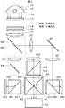
図1は、本発明の実施形態としての投射型映像表示装置の構成例であって、ライトバルブに反射型液晶パネルを用いた液晶プロジェクタ装置の場合の例を示す。 FIG. 1 is a configuration example of a projection type video display apparatus as an embodiment of the present invention, and shows an example of a liquid crystal projector apparatus using a reflection type liquid crystal panel as a light valve.
図1において、11は光源、12は放物反射面形状のリフレクタ、13、14はそれぞれ、インテグレータ光学系を構成する第1マルチレンズアレイ、第2マルチレンズアレイ、15はプリズムアレイから成る平板型偏光変換手段、16は集光レンズで、10はこれらから構成される照明光学系である。21、22はフィールドレンズ、23はリレーレンズ、18、19はダイクロイックミラー、20は、ダイクロイックミラー18、19から成る色分離手段、24は全反射ミラー、291、292、293はそれぞれ、S偏光光を透過させる入射側偏光板、301、302、303は、P偏光光を透過しS偏光光を反射することで偏光分離を行う偏光分離用構造体である偏光分離手段、411、412、413はP偏光光を透過させる出射側偏光板、401、402、403は、ライトバルブ(反射型ライトバルブ)としての反射型液晶パネル、42、43は、P偏光光とS偏光光を変換する1/2波長位相差板、44は色合成用のクロスダイクロイックプリズム、45は、色合成された光をスクリーン等に拡大投射する投射レンズユニットである。
In FIG. 1, 11 is a light source, 12 is a reflector having a parabolic reflecting surface shape, 13 and 14 are first multi-lens arrays and second multi-lens arrays constituting an integrator optical system, respectively, and 15 is a flat plate type comprising a prism array. Polarization conversion means, 16 is a condensing lens, and 10 is an illumination optical system composed of these. 21 and 22 are field lenses, 23 is a relay lens, 18 and 19 are dichroic mirrors, 20 is a color separation unit composed of
光源11から出射した光は、放物反射面形状のリフレクタ12で反射され、レンズアレイ方式のインテグレータ光学系に入射する。インテグレータ光学系は、リフレクタ12の出射開口と略同等サイズの矩形枠に設けられた矩形状の複数のレンズセルにより構成され、複数の2次光源像を形成するための第1レンズアレイ13と、同じく矩形状の複数のレンズセルにより構成され、前述の複数の2次光源像が形成される近傍に配置され、かつ反射型液晶パネル401、402、403に、第1レンズアレイ13の個々のレンズセル像を結像させる第2レンズアレイ14とから成る。インテグレータ光学系で複数光束に分割された各光束は、平板型偏光変換手段15で所定偏光方向(ここではS偏光光)に揃えられ、S偏光光に揃えられた各光束は、集光レンズ16により集光され、フィールドレンズ21、22により主光線が平行光とされた(テレセントリック化された)後、反射型液晶パネル401、402、403上に重畳して照射される。これにより、該反射型液晶パネル401、402、403には均一な光照射がなされる。なお、光源11、インテグレータ光学系、平板型偏光変換手段15、集光レンズ16は照明光学系を構成する。
The light emitted from the
集光レンズ16から出た光は、光軸に対し45°の角度で配置されたダイクロイックミラー18により、RG(赤色+緑色)光とB(青色)光に色分離され、RG光はダイクロイックミラー18を透過し、B光はダイクロイックミラー18を反射する。ダイクロイックミラー18を透過したRG光は、ダイクロイックミラー19によりR光とG光に色分離され、R光はダイクロイックミラー19を透過して反射型液晶パネル401に入射し、G光はダイクロイックミラー19を反射して、反射型液晶パネル402に入射する。一方、ダイクロイックミラー18を反射したB光は、リレーレンズ23を透過し、全反射ミラー24によりその光路を90°曲げられ、フィールドレンズ22で主光線が光軸に平行とされ、反射型液晶パネル403に入射する。なお、反射型液晶パネル403の光路長は他の2つの光路に比べて長いため、リレーレンズ23は他の2つの光路長より長い反射型液晶パネル403に照明光束を導く。
The light emitted from the
次に、各色光用の反射型液晶パネル401、402、403(以下、これらを総称して反射型液晶パネル40という)の手前に配置された各色光用の偏光分離手段301、302、303(以下、これらを総称して偏光分離手段30という)について説明する。
Next, polarization separation means 301, 302, 303 (for each color light) arranged in front of the reflection type
偏光分離手段30は、光の屈折率が1よりも大きい媒質中に偏光分離素子を配設した構成を有し、該偏光分離素子としては、ワイヤグリッド構造等の格子構造に基づく回折により光を偏光分離する偏光分離面を備え、該偏光分離面に接して空気層が形成された構成のものを用いる。該偏光分離素子では、前述のように、PBSプリズムに比べて偏光度が不足するため、偏光分離手段30の入射側に補助偏光子(S偏光光を透過)としての入射側偏光板291、292、293(以下、これらを総称して入射側偏光板29という)を設け、出射側に補助検光子(P偏光光を透過)としての出射側偏光板411、412、413(以下、これらを総称して出射側偏光板41という)を設ける。
The polarization separation means 30 has a configuration in which a polarization separation element is disposed in a medium having a light refractive index greater than 1, and the polarization separation element is configured to emit light by diffraction based on a lattice structure such as a wire grid structure. A structure having a polarization separation surface for separating polarization and having an air layer formed in contact with the polarization separation surface is used. As described above, since the polarization separation element has a degree of polarization that is insufficient as compared with the PBS prism, the incident-side
色分離手段20で色分離された各色光(S偏光光)は、対応する反射型液晶パネル40に向かうが、入射側偏光板29でS偏光光の偏光度が高められた後、偏光分離手段30により偏光分離されS偏光光のみが反射されて反射型液晶パネル40に略垂直に照射される。反射型液晶パネル40では、照射されたS偏光光は、画素毎に映像信号に応じて光強度変調され光学像を形成するとともに、偏光状態を変えられてP偏光光に変換される。光学像を形成しP偏光光に変換された状態で反射型液晶パネル40から反射される各色光は、再び偏光分離手段30に入射する。該P偏光光は、該偏光分離手段30の偏光分離素子で偏光分離され、該偏光分離手段30を透過する。偏光分離手段30を透過した該P偏光光は、出射側偏光板41で偏光度を増大され、さらに、クロスダイクロイックプリズム44で色合成される。
Each color light (S-polarized light) color-separated by the color separation means 20 goes to the corresponding reflective
反射型液晶パネル40は、駆動回路(図示なし)により映像信号に応じて駆動され、上記入射したS偏光光を画素毎に偏光方向を変えながら光強度変調し、映像信号に応じP偏光光の光学像を形成する。
The reflective
反射型液晶パネル40からの各色光の光学像のうち、R色光とB色光は1/2波長位相差板42、43でP偏光光がS偏光光に変換されて、クロスダイクロイックプリズム44で色合成されてカラーの光学像(画像)が形成され、投射レンズ45によりスクリーンなどに拡大投射される。なお、1/2波長位相差板42、43を配置せずに、全色光をP偏光光のままクロスダイクロイックプリズム44において色合成するようにしてもよい。
Of the optical images of each color light from the reflective
上記図1の構成において、光源11から投射レンズユニット45までの一連の光学系は、液晶プロジェクタ装置の照明光学系を含み構成される光学ユニットを形成している。
In the configuration of FIG. 1, a series of optical systems from the
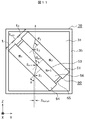
図2〜図3は、偏光分離手段30の第1の構成例の説明図である。図2は、偏光分離手段30の第1の構成例図、図3はその光線図である。本第1の構成例においては、偏光分離手段30を偏光分離手段30Aという。偏光分離手段30Aにおいて媒質中に設ける偏光分離素子には、空気層に接する偏光分離面がワイヤグリッド構造を備えたワイヤグリッド型偏光分離素子を用いる。
2 to 3 are explanatory diagrams of a first configuration example of the polarization separating means 30. FIG. FIG. 2 is a first structural example diagram of the polarization separating means 30, and FIG. 3 is a ray diagram thereof. In the first configuration example, the
図2において、偏光分離手段30Aは、外形形状が直方体であるガラスやプラスチックから成る透光性容器35と、その内部に充填された媒質としての液体31と、該液体31中に配設されたワイヤグリッド型偏光分離素子50とから成る。ワイヤグリッド型偏光分離素子50は、板厚t2が0.7×10⁻³mである透光性基板51と、その上に所定の周期間隔で形成された回折格子すなわち偏光分離面を形成した、例えばアルミニウムのワイヤグリッド(金属格子)52と、透光性基板51に対向して平行に配置され板厚t1が0.7×10⁻³mである透光性の平板54と、透光性基板51と平板54の周辺部側面を覆う側板55と、所定の間隔をあけて平行に配置された透光性基板51と平板54と側板55とで囲まれた空間内に空気が気密に充填されて形成された空気層56とから成る。偏光分離手段30Aの透光性容器35の1つの面(XY平面に平行)に反射型液晶パネル40が配設されており、ワイヤグリッド型偏光分離素子50は、反射型液晶パネル40から投射レンズ45に向かう光路上(Z軸方向)にθ°(ここでは45°)傾斜して配設されている。また、偏光分離手段30Aの透光性容器35の入射面35iには入射側偏光板29が、出射面には出射側偏光板41が設けられている。
In FIG. 2, the polarization separation means 30 </ b> A is disposed in the liquid 31, a
偏光分離手段30Aに入射する主光線L1は、先ず、入射側偏光板29で所定偏光方向(ここではS偏光光)の偏光度が高められ、偏光分離手段30Aに入射する。入射側偏光板29でS偏光度が高められた主光線L1のうち、P偏光光成分はワイヤグリッド型偏光分離素子50の偏光分離面を透過し、S偏光光成分は該偏光分離面で反射され、反射型液晶パネル40に入射する。反射型液晶パネル40では、S偏光光の入射光束を映像信号に応じて光強度変調してP偏光光の光学像を形成しZ軸方向に反射する。反射型液晶パネル40からのP偏光光の反射光は、ワイヤグリッド型偏光分離素子50を透過し、出射側偏光板41で検光されて投射レンズ45側に向かう。
The principal ray L1 incident on the polarization separation means 30A is first incident on the polarization separation means 30A after the polarization degree in a predetermined polarization direction (here, S-polarized light) is increased by the incident-side
なお、偏光分離手段30Aの入射側と出射側に設けた偏光板は、ワイヤグリッド型偏光分離素子50の偏光分離機能を補うためのものである。また、透光性基板51と平板54との間は空気で満たされ空気層56を形成している。該空気層56の厚さ(以下、「エア厚」という)が厚過ぎる場合は、反射型液晶パネル40からの反射光がワイヤグリッド型偏光分離素子50を透過する際に該空気層56で非点収差が発生する。このため、エア厚は適切な値とする必要がある。この点については、後述する。
The polarizing plates provided on the incident side and the outgoing side of the polarization separation means 30A are for supplementing the polarization separation function of the wire grid type
以上述べたように、上記ワイヤグリッド型偏光分離素子50は空気層56を有する構成のため、ワイヤグリッドの格子ピッチを、少なくとも空気中で用いる格子ピッチと同じとすることができる。このため、上記ワイヤグリッド型偏光分離素子50の製造が困難になるという問題はない。また、ワイヤグリッド型偏光分離素子50は、光の屈折率が空気よりも大きい液体31中に配設されているため、光路長を短くすることができ、投射レンズのバックフォーカスを短くして投射レンズを小型化することが可能となる。さらに、液体31で冷却することができ、投射性能の劣化や複屈折によるコントラスト低下を改善することができる。
As described above, the wire grid type
ワイヤグリッド型偏光分離素子50は、空気層56を備えているため、光の屈折率が大きい媒質と同屈折率が小さい媒質との境界で生じる全反射に対して注意する必要がある。以下、計算を容易とするために、平板54と液体31の光の屈折率は互いに略同じとする。例えば、液体31の光の屈折率が1.5である場合、空気層との間で全反射を起こす角度は、スネルの法則から41.8°(=sin−1(1/1.5))となる。ワイヤグリッド型偏光分離素子50に入射する光の光軸上のS偏光光のみならず、ワイヤグリッド型偏光分離素子50で透過すべきP偏光光も反射してしまう。偏光分離面で全反射が生じると消光比すなわちコントラストが劣化してしまうことがある。
Since the wire grid type
図3は、図2の偏光分離手段30Aにおける光線図である。 FIG. 3 is a ray diagram of the polarization separating means 30A shown in FIG.
図3において、53は,ワイヤグリッド型偏光分離素子50の偏光分離面(ワイヤグリッド構造が設けられ光を偏光分離する面)、Nは、媒質としての液体31における光の屈折率である。 In FIG. 3, 53 is a polarization separation surface of the wire grid type polarization separation element 50 (surface on which a wire grid structure is provided to separate and separate light), and N is a refractive index of light in the liquid 31 as a medium.
照明光学系から反射型液晶パネル40に入射して反射され、投射レンズユニットに入射する光束は、光軸に平行な平行光束の他、角度を有した光束もある。この角度を有する光束をF値に換算した値をFとすると、図3において、F値最大角の光線L2が、液体媒質と空気層との界面で全反射を起さないためには、入射面35iにおいて下記数2の関係を満足し、空気層56との界面で下記数3の関係を満足することが必要である。なお、θは光軸上の主光線L1の空気層界面、あるいは透光性の平板51、54での入射角であって、Z軸とワイヤグリッド型偏光分離素子とのなす角に等しい。
The luminous flux incident on the reflective
sinα=sin〔tan−1{1/(2F)}〕=Nsinβ …(数2)
Nsin(β+θ)<1 …(数3)
数2と数3とから下記数4が得られる。
sin α = sin [tan −1 {1 / (2F)}] = N sin β (Expression 2)
Nsin (β + θ) <1 (Equation 3)
The following equation 4 is obtained from the
θ<sin−1(1/N)
−sin−1[(1/N)sin〔tan−1{1/(2F)}〕]…(数4)
ただし、数4において、θ>0である。
θ <sin −1 (1 / N)
−sin −1 [(1 / N) sin [tan −1 {1 / (2F)}]] (Expression 4)
However, in Equation 4, θ> 0.
従って、媒質の光の屈折率Nが小さくて入射光線L2が上記数4を満足すれば、媒質とワイヤグリッド型偏光分離素子の空気層との界面では全反射が起きない。しかし、媒質の光の屈折率Nが大きく、上記数4を満足しない場合は全反射が起こり、偏光分離機能が劣化する。例えば、F=3、N=1.2の場合は、全反射が起きない入射角θは、数4から、48.6°未満の値となり、この結果、ワイヤグリッド型偏光分離素子を45°傾斜させても全反射は起きない。しかし、F=3、N=1.39であれば、全反射が起きない入射角θは39.2°未満の値となり、ワイヤグリッド型偏光分離素子を45°傾斜させた場合には全反射が起きる。なお、主光線の場合は、上記数4の右辺第2項がなくなるため、θは46°未満の値となり、偏光分離手段は、媒質とワイヤグリッド型偏光分離素子の空気層との界面で全反射は起きない。 Therefore, if the refractive index N of the light of the medium is small and the incident light beam L2 satisfies the above formula 4, total reflection does not occur at the interface between the medium and the air layer of the wire grid type polarization separation element. However, when the refractive index N of the light of the medium is large and the above formula 4 is not satisfied, total reflection occurs and the polarization separation function deteriorates. For example, in the case of F = 3 and N = 1.2, the incident angle θ at which total reflection does not occur is a value less than 48.6 ° from Equation 4, and as a result, the wire grid type polarization separation element is 45 °. Even if tilted, total reflection does not occur. However, when F = 3 and N = 1.39, the incident angle θ at which total reflection does not occur is less than 39.2 °, and total reflection occurs when the wire grid type polarization separation element is inclined 45 °. Happens. In the case of chief rays, since the second term on the right side of Equation 4 is eliminated, θ is a value less than 46 °, and the polarization separation means is entirely at the interface between the medium and the air layer of the wire grid type polarization separation element. There is no reflection.
図4〜図5は、偏光分離手段30の第2の構成例の説明図である。図4は、偏光分離手段30の第2の構成例図、図5はその光線図である。本第2の構成例においては、偏光分離手段30を偏光分離手段30Bという。偏光分離手段30Bにおいて媒質中に設ける偏光分離素子としては、上記第1の構成例の場合と同様、空気層に接する偏光分離面がワイヤグリッド構造を備えたワイヤグリッド型偏光分離素子50を用いる。本第2の構成例は、該ワイヤグリッド型偏光分離素子50がZ軸と成す角を、45°より所定角φだけ大きくし、主入射光線L3をY軸に対して2φ傾斜させ、全反射を回避できるようにした場合の例である。
4 to 5 are explanatory diagrams of a second configuration example of the polarization separating means 30. FIG. FIG. 4 is a diagram showing a second configuration example of the polarization separating means 30, and FIG. 5 is a ray diagram thereof. In the second configuration example, the
図4において、偏光分離手段30Bは、光の通る部分には透光性の窓37が設けられた金属容器36と、その内部に充填された媒質としての液体32と、液体32中に配設されたワイヤグリッド型偏光分離素子50とから成る。液体32としては、例えば、エチレングリコールとグリセリンの混合液であるGE55などを用いる。GE55の光の屈折率は1.45である。
In FIG. 4, the polarization separation means 30 </ b> B is disposed in the liquid 32, a
図5は、図4の偏光分離手段における光線図である。本図5では、入射側偏光板29、出射側偏光板41等の図示は省いてある。また、説明の便宜上、平板54と液体32の光の屈折率を略同じものとする。図5から明らかなように、ワイヤグリッド型偏光分離素子50は、Z軸に対して45°の傾斜位置から反時計方向に角度φだけずれた位置に配置されている。従って、ワイヤグリッド型偏光分離素子50で反射されたS偏光光がZ軸の負方向に向かうようにした場合、反射角は45°−φとなり、主光線L3のワイヤグリッド型偏光分離素子50への入射角も45°−φとなる。このとき、主光線L3がY軸と成す角は2φとなる。金属容器36の入射面36iはZ軸の負方向に対して2φ傾斜し、金属容器36の透光性の窓37に入射する主光線L3は入射面36iに垂直に入射する。
FIG. 5 is a ray diagram of the polarization separation means of FIG. In FIG. 5, the incident
このように構成された偏光分離手段30Bでは、主光線L3のワイヤグリッド型偏光分離素子50への入射角は45°−φとなるため、角度を持った光束(換算F値がFの光束)を考慮しても、空気層での全反射をなくすことができる。従って、偏光分離手段30Bに入射した入射光線のうちのS偏光光は、ワイヤグリッド型偏光分離素子50で反射して反射型液晶パネル40に入射し、光強度変調され光学像を形成するとともにP偏光光として該反射型液晶パネル40から反射される。該反射型液晶パネル40から出射されたP偏光光は、再び偏光分離手段30Bに入射し、偏光分離手段30B中のワイヤグリッド型偏光分離素子50を透過して、色合成用のクロスダイクロイックプリズム44側に出射される。クロスダイクロイックプリズム44で色合成された光はさらに、投射レンズユニット45側に出射される。
In the polarization separating means 30B configured in this way, the incident angle of the principal ray L3 to the wire grid type
従って、上記数4から算出するθを臨界入射角θmとすれば、上記角度φは次の数5を満たす必要がある。
Therefore, if θ calculated from the above equation 4 is the critical incident angle θ m , the angle φ needs to satisfy the
45−θm<φ …(数5)
例えば、媒質の光の屈折率Nを1.45、Fを3とすれば、数4から主光線の空気層界面での臨界入射角θmは37.1°となり、数5から、φは7.9°以上にする必要がある。φを7.9°以上とすれば、数4が満たされるため、空気層界面での全反射は生じない。
45−θ m <φ (Expression 5)
For example, if the refractive index N of the light of the medium is 1.45 and F is 3, the critical incident angle θ m at the air layer interface of the principal ray is 37.1 ° from Equation 4, and from
上記第2の構成例では、ワイヤグリッド型偏光分離素子50をZ軸に対し45°傾斜の位置から角度φだけ傾けて配置しているが、PBSプリズムの場合とは異なり、該ワイヤグリッド型偏光分離素子50の偏光分離特性の入射角に対する依存性が低いため、第1の構成の場合と同様、良好な偏光分離特性が得られる。
In the second configuration example, the wire grid type
図6は、偏光分離手段30の第3の構成例の説明図である。本第3の構成例においては、偏光分離手段30を偏光分離手段30Cという。偏光分離手段30Cにおいても媒質中に設ける偏光分離素子としては、上記第1、第2の構成例の場合と同様、空気層に接する偏光分離面がワイヤグリッド構造を備えたワイヤグリッド型偏光分離素子を用いる。本第3の構成例では、2つのプリズムの間にワイヤグリッド型偏光分離素子を配設する。 FIG. 6 is an explanatory diagram of a third configuration example of the polarization separation means 30. In the third configuration example, the polarization separation means 30 is referred to as polarization separation means 30C. Also in the polarization separation means 30C, the polarization separation element provided in the medium is a wire grid type polarization separation element in which the polarization separation surface in contact with the air layer has a wire grid structure as in the first and second configuration examples. Is used. In the third configuration example, a wire grid type polarization separation element is disposed between two prisms.
図6において、偏光分離手段30Cは、直角プリズム33と、これに対向するプリズム34と、直角プリズム33とプリズム34との間に配設されたワイヤグリッド型偏光分離素子60とから成る。そして、ワイヤグリッド型偏光分離素子60は、板厚が0.7×10⁻³mの透光性基板61と、その上に所定の周期間隔で形成された回折作用を有するすなわち偏光分離面を形成したワイヤグリッド(金属格子)62と、透光性基板61とプリズム34の周辺部側面を覆う側板65と、透光性基板61とプリズム34と側板65とで囲まれた空間内に空気が気密に充填されて形成された空気層66とから成る。プリズム34の、ワイヤグリッド型偏光分離素子60側面以外の一方の面341(XY平面に平行)に平行に、反射型液晶パネル40が配設されており、ワイヤグリッド型偏光分離素子60は、反射型液晶パネル40から投射レンズ45に向かう光路上(Z軸方向)に、上記第2の構成例の場合と同様に、Z軸に対して45°傾斜位置から反時計方向に角度φだけすれた位置に配置されている。また、プリズム34の入射面34iはZ軸の負方向に対して角度2φだけ傾斜しており、偏光分離手段30Cに入射する主光線L5はY軸に対して角度2φ傾斜している。従って、偏光分離手段30Cの入出射の光線図は、上記図5の場合と同様である。
In FIG. 6, the polarization separation means 30 </ b> C includes a right-
上記第3の構成例の偏光分離手段では、媒質がガラス例えばHOYA社のBSC7(商品名)であり、光の屈折率が1.52と、上記第2の構成例の液体媒質(例えば屈折率1.45)のそれよりも大きいため、45°傾斜位置からのずれ角度φを、液体媒質の場合よりも大きくする必要がある。例えば、ガラス媒質の屈折率Nを1.52、Fを3とすれば、数4から、主光線の空気層界面での臨海入射角θmは34.9°となる結果、角度φは、数5から、45°−34.9°=10.1°より大きくする必要があり、液体媒質の場合よりも大きい角度φが必要となる。
In the polarization separation means of the third configuration example, the medium is glass, for example, BSC7 (trade name) manufactured by HOYA, and the refractive index of light is 1.52, and the liquid medium (for example, refractive index) of the second configuration example is used. Since it is larger than that of 1.45), it is necessary to make the deviation angle φ from the 45 ° inclined position larger than in the case of the liquid medium. For example, if the refractive index N of the glass medium is 1.52 and F is 3, the seafront incident angle θ m at the air layer interface of the principal ray is 34.9 ° from Equation 4, and the angle φ is From
以上述べた偏光分離手段のワイヤグリッド型偏光分離素子は、空気層を備えているため、該空気層で発生する非点収差の影響を抑える必要がある。該非点収差の影響を抑えるには、該空気層の厚さを薄くすることが有効である。 Since the wire grid type polarization separation element of the polarization separation means described above includes an air layer, it is necessary to suppress the influence of astigmatism generated in the air layer. In order to suppress the influence of the astigmatism, it is effective to reduce the thickness of the air layer.
図7〜図9は、空気層を備えたワイヤグリッド型偏光分離素子を媒質中に配設した場合における空気層の厚さ(エア厚)と光束サイズ(スポットサイズ)の関係をシミュレーションにより求めた結果を示すグラフである。図10に、該シミュレーションの条件を示す。 7 to 9, the relationship between the air layer thickness (air thickness) and the light beam size (spot size) in the case where the wire grid type polarization separation element provided with the air layer is disposed in the medium is obtained by simulation. It is a graph which shows a result. FIG. 10 shows the simulation conditions.
図10(a)に示すように、0.8インチWIDEの反射型液晶パネル40上のスポット像を倍率約56倍の投射レンズユニット45で45インチのスクリーン90上に投射し、スクリーン90上の各点A〜Fでスポットサイズ比を求め、平均化する。スポットサイズの基準は、空気層の厚さが0.01×10⁻³mで、図10(b)に示すように、偏光分離手段30’の媒質中にワイヤグリッド型偏光分離素子50(60)を光軸に垂直となるように配設した場合のスポットサイズである。これを基準として各エア厚毎にスポットサイズ比を求める。各エア厚毎のスポットサイズは、図10(c)に示すように、偏光分離手段30の媒質中にワイヤグリッド型偏光分離素子50(60)を主光線の入射角が35°となるように傾斜させて配設し、求めた。そして、各エア厚で、投射レンズユニット45を構成する非球面レンズの2面の形状と、偏光分離手段30の媒質から投射レンズユニット45の1枚目のレンズまでの距離dとを変化させ、最適化してスポットサイズを求める。
As shown in FIG. 10A, a spot image on a 0.8-inch WIDE reflective
図7は、光の屈折率Nが1.3である偏光分離手段の液体媒質の場合、図8は、光の屈折率Nが1.45である液体媒質(例えばGE55)の場合、図9は、光の屈折率が1.52である媒質(例えばガラスBK7)の場合の、それぞれスポットサイズ比である。 FIG. 7 shows a case of a liquid medium of polarization separating means having a light refractive index N of 1.3, and FIG. 8 shows a case of a liquid medium having a light refractive index N of 1.45 (for example, GE55). Are spot size ratios in the case of a medium (for example, glass BK7) having a refractive index of light of 1.52.
図7では、空気層の厚さが約0.1〜0.15×10⁻³mのときに、スポットサイズ比が最小となり、また、図8では、空気層の厚さが約0.01×10⁻³m前後のときに、スポットサイズ比が最小となる。これは、図11に示すように、媒質より屈折率の低い空気層56が媒質より屈折率の高い透光性基板51と透光性の平板54の間にあり、これらにより生じる非点収差の方向が空気層と透光性基板51及び平板54では逆であるため、横収差が相殺され、所定の空気層の厚さでスポットサイズが最小になるためと考えられる。すなわち、空気層をはさんで両側に媒質より高い屈折率を有する平行平板(透光性基板も平行平板である)がある場合には、平行平板の板厚及び平行平板と媒質の光の屈折率差に対応した非点収差を最小にできる適切なエア厚が存在し、該適切なエア厚値にすることが望ましい。
In FIG. 7, when the thickness of the air layer is about 0.1 to 0.15 × 10 −3 m, the spot size ratio is minimized, and in FIG. 8, the thickness of the air layer is about 0.01. The spot size ratio is minimized when the distance is around × 10 −3 m. As shown in FIG. 11, the
これに対し、図9では、透光性基板51及び透光性の平板54の屈折率は媒質と同等であり、非点収差は空気層のみで生じるため、空気層の厚さを薄くするほど、非点収差は低減されることになる。透光性基板51及び透光性の平板54として、光の屈折率が媒質よりも高いものを使用した場合には、上記図7及び図8の場合と同様に、平行平板の板厚及び平行平板と媒質の光の屈折率差に対応した非点収差を最小にできる適切なエア厚があり、該適切なエア厚値にするのが望ましい。しかしながら、空気層の厚さを薄くし過ぎると干渉作用が生じるため、少なくとも約3/2λ(赤色λr=700×10−9m)である1×10−6m(ミクロン)以上であることが望ましい。
On the other hand, in FIG. 9, since the refractive index of the
上記本発明の実施形態によれば、上記ワイヤグリッド型偏光分離素子等格子構造に基づく回折により光を偏光分離する偏光分離素子を、光の屈折率が空気よりも大きい媒質中で用いた場合にも、偏光分離性の劣化を抑えることができる。このため、投射型映像表示装置において、偏光分離素子の温度上昇を抑えた状態で、非点収差を抑えて映像解像度を確保し、かつ明るさ及びコントラストを確保することができる。 According to the embodiment of the present invention, when the polarization separation element that separates light by diffraction based on the lattice structure such as the wire grid type polarization separation element is used in a medium in which the refractive index of light is larger than air. However, it is possible to suppress the deterioration of the polarization separation property. For this reason, in the projection type image display apparatus, it is possible to ensure image resolution, as well as brightness and contrast, while suppressing astigmatism while suppressing the temperature rise of the polarization separation element.
なお、上記実施形態では、偏光分離手段として、ワイヤグリッド型偏光分離素子を用いる構成としたが、本発明はこれに限定されるものではなく、例えば、透光性基板上に所定周期で光回折用の凹凸が形成されて成る偏光分離面を有した偏光分離素子を用いる構成などとしてもよい。また、ライトバルブは、反射型のライトバルブに限定されず、透過型のライトバルブであってもよい。また、該ライトバルブは、液晶パネル以外のものであってもよい。 In the above embodiment, the wire grid type polarization separation element is used as the polarization separation means. However, the present invention is not limited to this. For example, the light diffraction is performed on the translucent substrate at a predetermined period. For example, a configuration using a polarization separation element having a polarization separation surface formed with projections and depressions may be used. The light valve is not limited to a reflective light valve, and may be a transmissive light valve. The light valve may be other than a liquid crystal panel.
10…照明光学系、
11…光源、
12…リフレクタ、
13、14…マルチレンズアレイ、
15…平板型偏光変換手段、
16…集光レンズ、
21、22…フィールドレンズ、
23…リレーレンズ、
18、19…ダイクロイックミラー、
20…色分離手段、
24…全反射ミラー、
29、291、292、293…入射側偏光板、
30、301、302、303、30A、30B、30C…偏光分離手段、
31、32…液体、
33…直角プリズム、
34…プリズム、
35…透光性容器、
36…金属容器、
41、411、412、413…出射側偏光板、
40、401、402、403…反射型液晶パネル、
42、43…1/2波長位相差板、
44…クロスダイクロイックプリズム、
45…投射レンズユニット、
50、60…ワイヤグリッド型偏光分離素子、
51、61…透光性基板、
56、66…空気層。
10: Illumination optical system,
11 ... Light source,
12 ... Reflector,
13, 14 ... multi lens array,
15 ... Flat plate polarization conversion means,
16 ... Condensing lens,
21, 22 ... Field lens,
23 ... Relay lens,
18, 19 ... Dichroic mirror,
20 ... color separation means,
24 ... Total reflection mirror,
29, 291, 292, 293 ... incident side polarizing plate,
30, 301, 302, 303, 30A, 30B, 30C ... polarization separation means,
31, 32 ... Liquid,
33 ... right angle prism,
34 ... Prism,
35 ... translucent container,
36 ... Metal container,
41, 411, 412, 413... Exit side polarizing plate,
40, 401, 402, 403 ... reflective liquid crystal panel,
42, 43 ... 1/2 wavelength phase difference plate,
44. Cross dichroic prism,
45. Projection lens unit,
50, 60 ... wire grid type polarization separation element,
51, 61 ... translucent substrate,
56, 66 ... Air layer.
Claims (10)
格子構造に基づく回折により光を偏光分離する偏光分離面が、空気層を介して媒質中に形成され、上記ライトバルブに照射された光及び該ライトバルブで変調された光を偏光分離する偏光分離手段と、
上記偏光分離された光を色合成する色合成手段と、
上記色合成された光を拡大投射する投射レンズユニットと、
上記ライトバルブを駆動する駆動回路と、
を備えた構成を特徴とする投射型映像表示装置。 A projection-type image display device that converts light from a light source side into polarized light, irradiates a light valve, forms an optical image according to a video signal, and projects an enlarged image.
A polarization separation surface for polarizing and separating light by diffraction based on a grating structure is formed in a medium through an air layer, and polarization separation is performed to separate the light irradiated to the light valve and the light modulated by the light valve. Means,
Color synthesizing means for color synthesizing the polarized and separated light;
A projection lens unit for enlarging and projecting the color-synthesized light, and
A drive circuit for driving the light valve;
A projection-type image display device characterized by comprising a configuration.
光源側からの光の偏光方向を揃えP偏光光またはS偏光光を形成する偏光変換手段と、
上記偏光変換された偏光光を、R、G、Bの各色光に分離する分離手段と、
上記分離された各色光の偏光光が照射され映像信号に基づき該偏光光を変調するライトバルブと、
格子構造に基づく回折により光を偏光分離する偏光分離面が、空気層を介して媒質中に形成され、上記ライトバルブに照射された光及び該ライトバルブで変調された光を偏光分離する偏光分離手段と、
上記偏光分離された光を色合成する色合成手段と、
上記色合成された光を拡大投射する投射レンズユニットと、
上記ライトバルブを駆動する駆動回路と、
を備えた構成を特徴とする投射型映像表示装置。 A projection-type image display device that irradiates an image display element with light from a light source side, forms an optical image according to an image signal, and projects an enlarged image,
A polarization conversion means for aligning the polarization direction of light from the light source side to form P-polarized light or S-polarized light;
Separating means for separating the polarization-converted polarized light into R, G and B color lights;
A light valve that is irradiated with polarized light of each of the separated color lights and modulates the polarized light based on a video signal;
A polarization separation surface for polarizing and separating light by diffraction based on a grating structure is formed in a medium through an air layer, and polarization separation is performed to separate the light irradiated to the light valve and the light modulated by the light valve. Means,
Color synthesizing means for color synthesizing the polarized and separated light;
A projection lens unit for enlarging and projecting the color-synthesized light, and
A drive circuit for driving the light valve;
A projection-type image display device characterized by comprising a configuration.
0<θ<sin−1(1/N)
−sin−1[(1/N)sin〔tan−1{1/(2F)}〕]…(数1)
の範囲にある請求項1または請求項2に記載の投射型映像表示装置。 The F value of light modulated by the light valve and passing through the projection lens unit is F, the refractive index of light of the medium is N, the air layer of the polarization separation means of the principal ray emitted from the light valve, or When the incident angle to the light-transmitting flat plate forming the air layer is θ, the θ is
0 <θ <sin −1 (1 / N)
−sin −1 [(1 / N) sin [tan −1 {1 / (2F)}]] (Expression 1)
The projection-type image display device according to claim 1 or 2, wherein the projection-type image display device is in the range.
格子構造に基づく回折により光を偏光分離する偏光分離面が、空気層を介して媒質中に形成され、上記ライトバルブに照射された光及び該ライトバルブで変調された光を偏光分離する偏光分離手段と、
上記偏光分離された光を色合成する色合成手段と、
上記色合成された光を拡大投射する投射レンズユニットと、
を備えた構成を特徴とする光学ユニット。 An optical unit for a projection-type image display device that performs polarization conversion of light from a light source side, irradiates a light valve, forms an optical image according to a video signal, and projects an enlarged image.
A polarization separation surface for polarizing and separating light by diffraction based on a grating structure is formed in a medium through an air layer, and polarization separation is performed to separate the light irradiated to the light valve and the light modulated by the light valve. Means,
Color synthesizing means for color synthesizing the polarized and separated light;
A projection lens unit for enlarging and projecting the color-synthesized light, and
An optical unit characterized by comprising a structure.
光源側からの光の偏光方向を揃えP偏光光またはS偏光光を形成する偏光変換手段と、
上記偏光変換された偏光光を、R、G、Bの各色光に分離する分離手段と、
上記分離された各色光の偏光光が照射され映像信号に基づき該偏光光を変調するライトバルブと、
格子構造に基づく回折により光を偏光分離する偏光分離面が、空気層を介して媒質中に形成され、上記ライトバルブに照射された光及び該ライトバルブで変調された偏光光を偏光分離する偏光分離手段と、
上記偏光分離された光を色合成する色合成手段と、
上記色合成された光を拡大投射する投射レンズユニットと、
を備えた構成を特徴とする光学ユニット。 An optical unit for a projection-type image display device that irradiates an image display element with light from a light source side, forms an optical image according to an image signal, and projects an enlarged image.
A polarization conversion means for aligning the polarization direction of light from the light source side to form P-polarized light or S-polarized light;
Separating means for separating the polarization-converted polarized light into R, G and B color lights;
A light valve that is irradiated with polarized light of each of the separated color lights and modulates the polarized light based on a video signal;
Polarized light separating and polarizing the light by polarization based on the grating structure is formed in the medium through the air layer, and polarized light that separates the light irradiated to the light valve and the polarized light modulated by the light valve. Separating means;
Color synthesizing means for color synthesizing the polarized and separated light;
A projection lens unit for enlarging and projecting the color-synthesized light, and
An optical unit characterized by comprising a structure.
格子構造に基づく回折により光を偏光分離する偏光分離面が、空気層を介して媒質中に形成された構成を特徴とする偏光分離用構造体。 A polarization separation structure that separates polarized light from incident light,
A structure for polarization separation, characterized in that a polarization separation surface for polarizing and separating light by diffraction based on a grating structure is formed in a medium via an air layer.
The structure for polarization separation according to claim 9, wherein the medium is a light transmissive liquid, and the polarization separation surface is formed on a light transmissive flat plate.
Priority Applications (3)
| Application Number | Priority Date | Filing Date | Title |
|---|---|---|---|
| JP2004059569A JP4575682B2 (en) | 2004-03-03 | 2004-03-03 | Projection-type image display device and polarization separation structure |
| CNB2004100889873A CN100337143C (en) | 2004-03-03 | 2004-11-23 | Optical unit and projection-type image display apparatus using the same |
| US11/061,055 US7255444B2 (en) | 2004-03-03 | 2005-02-18 | Optical unit and projection-type image display apparatus using the same |
Applications Claiming Priority (1)
| Application Number | Priority Date | Filing Date | Title |
|---|---|---|---|
| JP2004059569A JP4575682B2 (en) | 2004-03-03 | 2004-03-03 | Projection-type image display device and polarization separation structure |
Publications (3)
| Publication Number | Publication Date |
|---|---|
| JP2005250057A true JP2005250057A (en) | 2005-09-15 |
| JP2005250057A5 JP2005250057A5 (en) | 2007-03-22 |
| JP4575682B2 JP4575682B2 (en) | 2010-11-04 |
Family
ID=35030598
Family Applications (1)
| Application Number | Title | Priority Date | Filing Date |
|---|---|---|---|
| JP2004059569A Expired - Fee Related JP4575682B2 (en) | 2004-03-03 | 2004-03-03 | Projection-type image display device and polarization separation structure |
Country Status (1)
| Country | Link |
|---|---|
| JP (1) | JP4575682B2 (en) |
Cited By (3)
| Publication number | Priority date | Publication date | Assignee | Title |
|---|---|---|---|---|
| JP2008021633A (en) * | 2006-07-14 | 2008-01-31 | Samsung Sdi Co Ltd | Organic light-emitting device |
| US8643793B2 (en) | 2011-03-14 | 2014-02-04 | Seiko Epson Corporation | Projector |
| CN114077143A (en) * | 2021-10-29 | 2022-02-22 | 歌尔光学科技有限公司 | Projection device, control method of projection device and projection system |
Citations (13)
| Publication number | Priority date | Publication date | Assignee | Title |
|---|---|---|---|---|
| JPH0527701U (en) * | 1991-09-13 | 1993-04-09 | パイオニア株式会社 | Projection display device |
| JPH05323118A (en) * | 1992-05-20 | 1993-12-07 | Matsushita Electric Ind Co Ltd | Polarizing device and projection type display device using same |
| JPH05323121A (en) * | 1992-05-22 | 1993-12-07 | Pioneer Electron Corp | Projection type display device |
| JPH06317771A (en) * | 1993-05-07 | 1994-11-15 | Victor Co Of Japan Ltd | Display device |
| JPH0868966A (en) * | 1994-08-30 | 1996-03-12 | Victor Co Of Japan Ltd | Display device formed by using polarization beam splitter |
| JPH10326080A (en) * | 1997-03-24 | 1998-12-08 | Sony Corp | Video display device and method |
| JPH11202132A (en) * | 1998-01-20 | 1999-07-30 | Fujitsu General Ltd | Polarizing prism and reflection type optical modulating projector |
| JPH11202432A (en) * | 1998-01-16 | 1999-07-30 | Sharp Corp | Projection type image display device |
| WO2001013162A1 (en) * | 1999-08-13 | 2001-02-22 | Seiko Epson Corporation | Polarized light illuminator and projection display |
| WO2002095496A1 (en) * | 2001-05-21 | 2002-11-28 | Moxtek | Image projection system with a polarizing beam splitter |
| JP2002365591A (en) * | 2001-06-04 | 2002-12-18 | Hitachi Ltd | Optical unit and video display device using the same |
| JP2003195223A (en) * | 2001-10-01 | 2003-07-09 | Sony Corp | Prism, projection device and optical component |
| JP2005250054A (en) * | 2004-03-03 | 2005-09-15 | Hitachi Ltd | Projection type image display apparatus and optical unit used for the same |
-
2004
- 2004-03-03 JP JP2004059569A patent/JP4575682B2/en not_active Expired - Fee Related
Patent Citations (13)
| Publication number | Priority date | Publication date | Assignee | Title |
|---|---|---|---|---|
| JPH0527701U (en) * | 1991-09-13 | 1993-04-09 | パイオニア株式会社 | Projection display device |
| JPH05323118A (en) * | 1992-05-20 | 1993-12-07 | Matsushita Electric Ind Co Ltd | Polarizing device and projection type display device using same |
| JPH05323121A (en) * | 1992-05-22 | 1993-12-07 | Pioneer Electron Corp | Projection type display device |
| JPH06317771A (en) * | 1993-05-07 | 1994-11-15 | Victor Co Of Japan Ltd | Display device |
| JPH0868966A (en) * | 1994-08-30 | 1996-03-12 | Victor Co Of Japan Ltd | Display device formed by using polarization beam splitter |
| JPH10326080A (en) * | 1997-03-24 | 1998-12-08 | Sony Corp | Video display device and method |
| JPH11202432A (en) * | 1998-01-16 | 1999-07-30 | Sharp Corp | Projection type image display device |
| JPH11202132A (en) * | 1998-01-20 | 1999-07-30 | Fujitsu General Ltd | Polarizing prism and reflection type optical modulating projector |
| WO2001013162A1 (en) * | 1999-08-13 | 2001-02-22 | Seiko Epson Corporation | Polarized light illuminator and projection display |
| WO2002095496A1 (en) * | 2001-05-21 | 2002-11-28 | Moxtek | Image projection system with a polarizing beam splitter |
| JP2002365591A (en) * | 2001-06-04 | 2002-12-18 | Hitachi Ltd | Optical unit and video display device using the same |
| JP2003195223A (en) * | 2001-10-01 | 2003-07-09 | Sony Corp | Prism, projection device and optical component |
| JP2005250054A (en) * | 2004-03-03 | 2005-09-15 | Hitachi Ltd | Projection type image display apparatus and optical unit used for the same |
Cited By (5)
| Publication number | Priority date | Publication date | Assignee | Title |
|---|---|---|---|---|
| JP2008021633A (en) * | 2006-07-14 | 2008-01-31 | Samsung Sdi Co Ltd | Organic light-emitting device |
| US7947973B2 (en) | 2006-07-14 | 2011-05-24 | Samsung Mobile Display Co., Ltd. | Organic light-emitting device |
| JP4695616B2 (en) * | 2006-07-14 | 2011-06-08 | 三星モバイルディスプレイ株式會社 | Organic light emitting device |
| US8643793B2 (en) | 2011-03-14 | 2014-02-04 | Seiko Epson Corporation | Projector |
| CN114077143A (en) * | 2021-10-29 | 2022-02-22 | 歌尔光学科技有限公司 | Projection device, control method of projection device and projection system |
Also Published As
| Publication number | Publication date |
|---|---|
| JP4575682B2 (en) | 2010-11-04 |
Similar Documents
| Publication | Publication Date | Title |
|---|---|---|
| US7255444B2 (en) | Optical unit and projection-type image display apparatus using the same | |
| JP4652110B2 (en) | Projection-type image display device | |
| US7502078B2 (en) | Projection type display apparatus with means for supplying an air cooling stream to a gap between a light receiving surface of a prism and a third surface of a closed triangular prismatic housing | |
| JP4935089B2 (en) | Projection-type image display device | |
| JP2007011248A (en) | Projection type display apparatus | |
| JP4880957B2 (en) | Illumination optical system and projection display device using the same | |
| JP2006145644A (en) | Polarization splitter and projection display apparatus using the same | |
| JP2006276826A (en) | Reflection type projection display apparatus | |
| US7354162B2 (en) | Projector | |
| JP2004078159A (en) | Projection display device | |
| US7472995B2 (en) | Wavelength-selective polarization conversion element, projection displaying optical system and image projection apparatus | |
| JP2007226092A (en) | Manufacturing method of optical element, manufacturing method of projector, the optical element, and the projector | |
| JP2002182195A (en) | Projection type display | |
| JP4258293B2 (en) | Projection-type image display device | |
| JP3951897B2 (en) | Polarization conversion unit and projector using the same | |
| JP4539319B2 (en) | Projection display | |
| JP2003131212A (en) | Projection type display device | |
| JP4575682B2 (en) | Projection-type image display device and polarization separation structure | |
| JP4444745B2 (en) | Polarization separation element and image projection apparatus | |
| JP2001083604A (en) | Luminous flux compressing means, optical engine and video display device using the same | |
| JP2007279763A (en) | Projection type video display apparatus | |
| JP4939070B2 (en) | Illumination optical system and image projection apparatus | |
| JP3659209B2 (en) | Optical unit and image display device using the same | |
| JP2005250054A (en) | Projection type image display apparatus and optical unit used for the same | |
| JP2768345B2 (en) | LCD projector |
Legal Events
| Date | Code | Title | Description |
|---|---|---|---|
| A521 | Written amendment |
Free format text: JAPANESE INTERMEDIATE CODE: A523 Effective date: 20070206 |
|
| A621 | Written request for application examination |
Free format text: JAPANESE INTERMEDIATE CODE: A621 Effective date: 20070206 |
|
| RD02 | Notification of acceptance of power of attorney |
Free format text: JAPANESE INTERMEDIATE CODE: A7422 Effective date: 20070206 |
|
| A977 | Report on retrieval |
Free format text: JAPANESE INTERMEDIATE CODE: A971007 Effective date: 20100311 |
|
| A131 | Notification of reasons for refusal |
Free format text: JAPANESE INTERMEDIATE CODE: A131 Effective date: 20100323 |
|
| A521 | Written amendment |
Free format text: JAPANESE INTERMEDIATE CODE: A523 Effective date: 20100520 |
|
| TRDD | Decision of grant or rejection written | ||
| A01 | Written decision to grant a patent or to grant a registration (utility model) |
Free format text: JAPANESE INTERMEDIATE CODE: A01 Effective date: 20100803 |
|
| A01 | Written decision to grant a patent or to grant a registration (utility model) |
Free format text: JAPANESE INTERMEDIATE CODE: A01 |
|
| A61 | First payment of annual fees (during grant procedure) |
Free format text: JAPANESE INTERMEDIATE CODE: A61 Effective date: 20100820 |
|
| R150 | Certificate of patent or registration of utility model |
Free format text: JAPANESE INTERMEDIATE CODE: R150 |
|
| FPAY | Renewal fee payment (event date is renewal date of database) |
Free format text: PAYMENT UNTIL: 20130827 Year of fee payment: 3 |
|
| S111 | Request for change of ownership or part of ownership |
Free format text: JAPANESE INTERMEDIATE CODE: R313111 |
|
| R350 | Written notification of registration of transfer |
Free format text: JAPANESE INTERMEDIATE CODE: R350 |
|
| S111 | Request for change of ownership or part of ownership |
Free format text: JAPANESE INTERMEDIATE CODE: R313111 |
|
| R350 | Written notification of registration of transfer |
Free format text: JAPANESE INTERMEDIATE CODE: R350 |
|
| LAPS | Cancellation because of no payment of annual fees |