JP2005249471A - Pressure sensor and method for manufacturing the same - Google Patents
Pressure sensor and method for manufacturing the same Download PDFInfo
- Publication number
- JP2005249471A JP2005249471A JP2004057644A JP2004057644A JP2005249471A JP 2005249471 A JP2005249471 A JP 2005249471A JP 2004057644 A JP2004057644 A JP 2004057644A JP 2004057644 A JP2004057644 A JP 2004057644A JP 2005249471 A JP2005249471 A JP 2005249471A
- Authority
- JP
- Japan
- Prior art keywords
- substrate
- housing
- spring
- metal
- circuit
- Prior art date
- Legal status (The legal status is an assumption and is not a legal conclusion. Google has not performed a legal analysis and makes no representation as to the accuracy of the status listed.)
- Withdrawn
Links
Images


Abstract
Description
本発明は、圧力検出部が形成されたダイヤフラムを有するステムを圧力導入可能なハウジングにネジ、かしめ、溶接等の方法で固定してなる圧力センサおよびその製造方法に関する。 The present invention relates to a pressure sensor formed by fixing a stem having a diaphragm in which a pressure detection unit is formed to a housing capable of introducing pressure by a method such as screwing, caulking, or welding, and a manufacturing method thereof.
従来より、圧力センサ内部の構造を簡略化し、小型な圧力センサを実現できる構造が提案されている(例えば、特許文献1参照)。図5に、従来の圧力センサの概略断面図を示す。この図に示されるように、圧力センサは、ハウジングJ1と、六角ケーシングJ2と、機器コネクタJ3とを備えて構成されている。 Conventionally, a structure capable of simplifying the structure inside the pressure sensor and realizing a small pressure sensor has been proposed (see, for example, Patent Document 1). FIG. 5 shows a schematic sectional view of a conventional pressure sensor. As shown in this figure, the pressure sensor includes a housing J1, a hexagon casing J2, and a device connector J3.
ハウジングJ1は中空形状の金属で構成され、被測定体に設置されることでボディアースとしての役割を果たすものである。このハウジングJ1の一端側には、金属で構成される六角ケーシングJ2が固定されている。ハウジングJ1には被測定体から圧力を導入する圧力導入孔J4が設けられており、この圧力導入孔J4の終端部にダイヤフラムを備えた圧力測定セルJ5が配置されている。この圧力測定セルJ5上には、集積回路を有する基板J6が備えられており、基板J6の集積回路は裏面に設けられたコンタクト面J7を介して圧力測定セルJ5と電気的に接続されている。また、基板J6の集積回路においてグランドとされる電位が、基板J6に設置された導電性接着剤J8を介してハウジングJ1の一部J11に電気的に接続されている。 The housing J1 is made of a hollow metal, and plays a role as a body ground by being installed on a measurement object. A hexagon casing J2 made of metal is fixed to one end side of the housing J1. The housing J1 is provided with a pressure introduction hole J4 for introducing pressure from the measurement object, and a pressure measurement cell J5 having a diaphragm is disposed at the end of the pressure introduction hole J4. A substrate J6 having an integrated circuit is provided on the pressure measurement cell J5, and the integrated circuit of the substrate J6 is electrically connected to the pressure measurement cell J5 through a contact surface J7 provided on the back surface. . In addition, a potential that is grounded in the integrated circuit of the substrate J6 is electrically connected to a part J11 of the housing J1 through a conductive adhesive J8 installed on the substrate J6.
上記のように、ハウジングJ1と基板J6とは、導電性接着剤J8を介して電気的に接続されている。具体的には、基板J6の集積回路から基板J6の裏面に配線が延設され、その配線が基板J6の裏面に設けられた電極部(図示しない)に接続されている。そして、その電極部に導電性接着剤J8、例えば銀ペーストが塗布されており、基板J6がハウジングJ1の一部J11に接着されている。このようにして、基板J6の集積回路とハウジングJ1との電気的導通状態が図られ、集積回路の所定電位がハウジングJ1に電気的に接続されることとなる。
しかしながら、ハウジングJ1と基板J6の回路との電気的導通を図るために、基板J6の裏面に導電性接着剤J8を塗布する工程、ハウジングJ1に対する基板J6の位置決めを行い導電性接着剤J8の加熱硬化する工程が必要になっている。 However, in order to achieve electrical continuity between the housing J1 and the circuit of the substrate J6, the step of applying the conductive adhesive J8 to the back surface of the substrate J6, positioning the substrate J6 with respect to the housing J1, and heating the conductive adhesive J8 A process of curing is required.
このように、2段階の工程が必要になっているのは、導電性接着剤J8を介して基板J6とハウジングJ1とを電気的に接続しているからであり、これが工程数を増やしている原因になっている。すなわち、導電性接着剤J8を基板J6の裏面に塗布し、さらに基板J8をハウジングJ1に設置して加熱しなければ、導電性接着剤J8を溶かして基板J6をハウジングJ1に接着することができない。このように、基板J6とハウジングJ1とを電気的に接続する従来の方法では、基板J6をハウジングJ1に固定および電気的に接続するための工程が煩雑になっている。 The reason why the two-step process is necessary is that the substrate J6 and the housing J1 are electrically connected via the conductive adhesive J8, which increases the number of processes. It is the cause. That is, unless the conductive adhesive J8 is applied to the back surface of the substrate J6, and the substrate J8 is further placed on the housing J1 and heated, the conductive adhesive J8 cannot be melted to bond the substrate J6 to the housing J1. . Thus, in the conventional method for electrically connecting the substrate J6 and the housing J1, the process for fixing and electrically connecting the substrate J6 to the housing J1 is complicated.
本発明は、上記点に鑑み、基板の回路とハウジングとを電気的に接続する圧力センサにおいて、基板を容易にハウジングに固定でき、かつ、基板の回路とハウジングとの電気的導通を図ることができる圧力センサおよびその製造方法を提供することを目的とする。 In view of the above points, the present invention can easily fix a substrate to the housing in a pressure sensor that electrically connects the circuit of the substrate and the housing, and can achieve electrical continuity between the circuit of the substrate and the housing. An object of the present invention is to provide a pressure sensor that can be used and a method for manufacturing the same.
上記目的を達成するため、請求項1に記載の発明では、中空形状の一端側に圧力導入孔(13)を有し、所定の電位とされる部位に接続される金属ハウジング(10)と、中空筒形状であって、この中空筒形状の軸の一端側に金属ハウジングに導入された圧力によって変形可能なダイヤフラム(22)を有し、軸の他端側に圧力導入孔と連通する通路(23)を有するステム(20)と、ダイヤフラム上に設けられ、ダイヤフラムの変形に応じた電気信号を出力する検出部(24)と、裏面(35)にバネ部(36)を有すると共に電気信号を受け取り、この電気信号に応じた出力信号を作成する回路を有する基板(30)と、出力信号を外部に出力するターミナル(50)と、を備え、金属ハウジングの他端側の内壁面(15)には、その内壁面が凹んだ凹部(16)が形成されており、バネ部は、金属部材で構成されると共に、回路と電気的に接続される曲げ部(36b)と、金属ハウジングの凹部に当接する引っ掛け部(36a)とを有し、金属ハウジングの凹部が、バネ部の弾性力によってバネ部の引っ掛け部に押さえつけられていることにより、回路がバネ部および金属ハウジングを通じて所定の電位に接続されるようになっていることを特徴としている。 To achieve the above object, according to the first aspect of the present invention, a metal housing (10) having a pressure introduction hole (13) on one end side of a hollow shape and connected to a portion having a predetermined potential; A hollow cylindrical shape having a diaphragm (22) deformable by pressure introduced into the metal housing on one end side of the hollow cylindrical shaft, and a passage communicating with the pressure introduction hole on the other end side of the shaft ( 23), a stem (20) provided on the diaphragm, a detection unit (24) for outputting an electric signal corresponding to the deformation of the diaphragm, and a spring part (36) on the back surface (35) and an electric signal. A substrate (30) having a circuit for receiving and generating an output signal corresponding to the electrical signal, and a terminal (50) for outputting the output signal to the outside, an inner wall surface (15) on the other end side of the metal housing The A recessed portion (16) having a recessed wall surface is formed, the spring portion is made of a metal member, a bent portion (36b) electrically connected to the circuit, and a hook portion that contacts the recessed portion of the metal housing (36a), and the concave portion of the metal housing is pressed against the hook portion of the spring portion by the elastic force of the spring portion, so that the circuit is connected to a predetermined potential through the spring portion and the metal housing. It is characterized by becoming.
このように、バネ部の引っ掛け部をハウジングの凹部に当接したときに、引っ掛け部がバネ部の弾性力によってハウジングの凹部を押さえつけることで、引っ掛け部をハウジングの凹部に確実に固定することができる。したがって、バネ部の引っ掛け部をハウジングの凹部にはめ込むだけなので、バネ部を介して基板をハウジングに容易に固定する構造とすることができる。 As described above, when the hook portion of the spring portion comes into contact with the concave portion of the housing, the hook portion presses the concave portion of the housing by the elastic force of the spring portion, so that the hook portion can be securely fixed to the concave portion of the housing. it can. Accordingly, since the hook portion of the spring portion is merely fitted into the recess portion of the housing, the substrate can be easily fixed to the housing via the spring portion.
また、各バネ部は、基板の回路と電気的に接続されており、バネ部の引っ掛け部がハウジングの凹部にバネ部のバネ性によって密着していることから、バネ部を介して基板の回路とハウジングとを電気的に接続することができる。 Each spring part is electrically connected to the circuit of the board, and the hook part of the spring part is in close contact with the concave part of the housing due to the spring property of the spring part. And the housing can be electrically connected.
請求項2に記載の発明では、圧力導入孔(13)を有し、所定の電位とされる部位に設置される金属ハウジング(10)と、中空筒形状であって、この中空筒形状の軸の一端側に金属ハウジングに導入された圧力によって変形可能なダイヤフラム(22)を有し、軸の他端側に圧力導入孔と連通する通路(23)を有すると共に、金属ハウジングに直接固定される金属ステム(20)と、ダイヤフラム上に設けられ、ダイヤフラムの変形に応じた電気信号を出力する検出部(24)と、裏面(35)にバネ部(36)を有すると共に電気信号を受け取り、この電気信号に応じた出力信号を作成する回路を有する基板(30)と、出力信号を外部に出力するターミナル(50)と、を備え、金属ステムの外壁面においては、その外壁面が凹んだ凹部(25)が形成されており、バネ部は、金属部材で構成されると共に、回路と電気的に接続される曲げ部(36b)と、金属ステムの凹部に当接する引っ掛け部(36a)とを有し、金属ステムの凹部が、バネ部の弾性力によってバネ部の引っ掛け部に押さえつけられていることにより、回路が前記バネ部、金属ステムおよび金属ハウジングを通じて所定の電位に接続されるようになっていることを特徴としている。 In the second aspect of the present invention, the metal housing (10) which has the pressure introduction hole (13) and is installed at a predetermined electric potential and the hollow cylindrical shape, the hollow cylindrical shaft A diaphragm (22) that can be deformed by pressure introduced into the metal housing is provided at one end of the shaft, and a passage (23) that communicates with the pressure introduction hole is provided at the other end of the shaft, and is directly fixed to the metal housing. A metal stem (20), a detector (24) provided on the diaphragm and outputting an electrical signal corresponding to the deformation of the diaphragm, and a spring (36) on the back surface (35) and receiving the electrical signal, A substrate (30) having a circuit for generating an output signal corresponding to an electrical signal and a terminal (50) for outputting the output signal to the outside are provided, and the outer wall surface of the metal stem is recessed. The spring part is made of a metal member, and a bent part (36b) that is electrically connected to the circuit, and a hook part (36a) that contacts the concave part of the metal stem. And the concave portion of the metal stem is pressed against the hook portion of the spring portion by the elastic force of the spring portion, so that the circuit is connected to a predetermined potential through the spring portion, the metal stem and the metal housing. It is characterized by becoming.
このように、バネ部の引っ掛け部をステムの凹部に当接したときに、引っ掛け部がバネ部の弾性力によって金属ステムの凹部を押し込むことになる。これにより、引っ掛け部が金属ステムの凹部を確実に固定することになるので、基板を金属ハウジングに固定する構造とすることができる。また、バネ部の引っ掛け部を金属ステムの凹部にはめ込むだけなので、バネ部を介して基板を金属ハウジングに容易に固定することができる。 As described above, when the hook portion of the spring portion comes into contact with the concave portion of the stem, the hook portion pushes the concave portion of the metal stem by the elastic force of the spring portion. As a result, the hook portion reliably fixes the concave portion of the metal stem, so that the substrate can be fixed to the metal housing. In addition, since the hook portion of the spring portion is simply fitted into the concave portion of the metal stem, the substrate can be easily fixed to the metal housing via the spring portion.
さらに、バネ部は、基板の回路と電気的に接続されており、バネ部の引っ掛け部が金属ステムの凹部にバネ部の弾性力によって密着していることから、バネ部を介して基板の回路を金属ステムに電気的に接続することができる。さらに、金属ステムが直接金属ハウジングに設置されている。すなわち、金属ステムと金属ハウジングとが電気的に接続されていることから、バネ部および金属ステムを介して基板の回路と金属ハウジングとを電気的に接続することができる。 Furthermore, since the spring portion is electrically connected to the circuit of the substrate, and the hook portion of the spring portion is in close contact with the recess of the metal stem by the elastic force of the spring portion, the circuit of the substrate is interposed via the spring portion. Can be electrically connected to the metal stem. In addition, a metal stem is installed directly on the metal housing. That is, since the metal stem and the metal housing are electrically connected, the circuit of the substrate and the metal housing can be electrically connected via the spring portion and the metal stem.
請求項3に記載の発明では、凹部および引っ掛け部は、湾曲形状で構成されていることを特徴としている。
The invention according to
このように、引っ掛け部の形状を湾曲形状とし、その引っ掛け部を固定する凹部の形状を引っ掛け部と同じ湾曲形状とすることで、引っ掛け部の凹部に対する密着面積を確保することができる構造とすることができる。 Thus, the shape of the hook portion is a curved shape, and the shape of the concave portion that fixes the hook portion is the same curved shape as the hook portion, so that the contact area of the hook portion with the concave portion can be secured. be able to.
請求項4に記載の発明では、中空形状の一端側に圧力導入孔(13)を有し、所定の電位とされる部位に接続される金属ハウジング(10)と、中空筒形状であって、この中空筒形状の軸の一端側に金属ハウジングに導入された圧力によって変形可能なダイヤフラム(22)を有し、軸の他端側に圧力導入孔と連通する通路(23)を有するステム(20)と、ダイヤフラム上に設けられ、ダイヤフラムの変形に応じた電気信号を出力する検出部(24)と、裏面(35)にバネ部(36)を有すると共に電気信号を受け取り、この電気信号に応じた出力信号を作成する回路を有する基板(30)と、出力信号を外部に出力するターミナル(50)と、を備える圧力センサの製造方法であって、金属ハウジングとして、その他端側の内壁面(15)が凹んだ凹部(16)を有するものを用意する工程と、金属部材であって、回路と電気的に接続する曲げ部(36b)と、金属ハウジングの凹部に当接する引っ掛け部(36a)とを有するバネ部(36)を用意する工程と、バネ部において、曲げ部を基板の裏面の所望の位置に接合する工程と、基板を金属ハウジングの他端側から一端側に差し込むと共に、バネ部の弾性力によって引っ掛け部を凹部に押しつける工程と、を有することを特徴としている。 In the invention according to claim 4, the metal housing (10) which has a pressure introduction hole (13) on one end side of the hollow shape and is connected to a portion which is set to a predetermined potential, and has a hollow cylindrical shape, A stem (20) having a diaphragm (22) deformable by pressure introduced into the metal housing on one end side of the hollow cylindrical shaft and a passage (23) communicating with the pressure introducing hole on the other end side of the shaft. ) And a detector (24) provided on the diaphragm for outputting an electric signal corresponding to the deformation of the diaphragm, and a spring part (36) on the back surface (35) and receiving the electric signal, and according to the electric signal. The pressure sensor includes a substrate (30) having a circuit for generating an output signal, and a terminal (50) for outputting the output signal to the outside. 5) preparing a step having a recessed portion (16) having a recess, a bent portion (36b) which is a metal member and is electrically connected to the circuit, and a hook portion (36a) contacting the recessed portion of the metal housing A step of preparing a spring portion (36) having the following: a step of joining the bent portion to a desired position on the back surface of the substrate in the spring portion, and inserting the substrate from the other end side to the one end side of the metal housing; And a step of pressing the hook portion against the concave portion by the elastic force of the portion.
このように、バネ部を介して基板をハウジングに固定することができる。すなわち、バネ部の引っ掛け部をハウジングの凹部にバネ部の弾性力によって押さえつけるだけであるので、容易に基板をハウジングに固定することができる。また、バネ部は金属部材でできているので、基板の回路とハウジングとをバネ部を介して電気的に接続することができる。 In this way, the substrate can be fixed to the housing via the spring portion. That is, since the hook portion of the spring portion is only pressed against the concave portion of the housing by the elastic force of the spring portion, the substrate can be easily fixed to the housing. Moreover, since the spring part is made of a metal member, the circuit of the substrate and the housing can be electrically connected via the spring part.
請求項5に記載の発明では、圧力導入孔(13)を有し、所定の電位とされる部位に設置される金属ハウジング(10)と、中空筒形状であって、この中空筒形状の軸の一端側に金属ハウジングに導入された圧力によって変形可能なダイヤフラム(22)を有し、軸の他端側に圧力導入孔と連通する通路(23)を有すると共に、金属ハウジングに直接固定される金属ステム(20)と、ダイヤフラム上に設けられ、ダイヤフラムの変形に応じた電気信号を出力する検出部(24)と、裏面(35)にバネ部(36)を有すると共に電気信号を受け取り、この電気信号に応じた出力信号を作成する回路を有する基板(30)と、出力信号を外部に出力するターミナル(50)と、を備える圧力センサの製造方法であって、金属ステムとして、その外壁面が凹んだ凹部(25)を有するものを用意する工程と、金属部材であって、回路と電気的に接続する曲げ部(36b)と、金属ステムの凹部に当接する引っ掛け部(36a)とを有するバネ部(36)を用意する工程と、バネ部において、曲げ部を基板の裏面の所望の位置に接合する工程と、基板を金属ハウジングにおいて圧力導入孔が形成される側とは反対側から差し込むと共に、バネ部の弾性力によって引っ掛け部を金属ステムの凹部に押しつける工程と、を有することを特徴としている。 In the invention according to claim 5, there is provided a metal housing (10) having a pressure introduction hole (13) and installed at a predetermined electric potential, a hollow cylindrical shape, and the hollow cylindrical shaft A diaphragm (22) that can be deformed by pressure introduced into the metal housing is provided at one end of the shaft, and a passage (23) that communicates with the pressure introduction hole is provided at the other end of the shaft, and is directly fixed to the metal housing. A metal stem (20), a detector (24) provided on the diaphragm and outputting an electrical signal corresponding to the deformation of the diaphragm, and a spring (36) on the back surface (35) and receiving the electrical signal, A pressure sensor manufacturing method comprising a substrate (30) having a circuit for generating an output signal corresponding to an electric signal, and a terminal (50) for outputting the output signal to the outside, wherein the metal stem is A step having a recessed portion (25) whose outer wall surface is recessed, a bent portion (36b) that is a metal member and is electrically connected to the circuit, and a hook portion (36a) that contacts the recessed portion of the metal stem. The step of preparing a spring portion (36) having the following structure: the step of joining the bent portion to a desired position on the back surface of the substrate in the spring portion, and the side where the pressure introduction hole is formed in the metal housing A step of inserting from the opposite side and pressing the hook portion against the concave portion of the metal stem by the elastic force of the spring portion.
このように、バネ部を金属ステムに固定することにより、基板を金属ハウジングに固定することができる。すなわち、バネ部の引っ掛け部を金属ステムの凹部にバネ部の弾性力によって押さえつけるだけであるので、容易に基板を金属ハウジングに固定することができる。また、バネ部は金属部材でできており、金属ステムが直接金属ハウジングに固定されていることから、基板の回路と金属ハウジングとをバネ部および金属ステムを介して電気的に接続することができる。 Thus, by fixing the spring portion to the metal stem, the substrate can be fixed to the metal housing. That is, since the hook portion of the spring portion is only pressed against the concave portion of the metal stem by the elastic force of the spring portion, the substrate can be easily fixed to the metal housing. Further, since the spring portion is made of a metal member and the metal stem is directly fixed to the metal housing, the circuit of the board and the metal housing can be electrically connected via the spring portion and the metal stem. .
請求項6に記載の発明では、凹部および引っ掛け部は、湾曲形状で構成されていることを特徴としている。 The invention according to claim 6 is characterized in that the concave portion and the hooking portion are formed in a curved shape.
このように、引っ掛け部の形状を湾曲形状とし、その引っ掛け部を固定する凹部の形状を引っ掛け部と同じ湾曲形状とすることで、引っ掛け部の凹部に対する密着面積を確保することができる。これにより、引っ掛け部を凹部により確実に固定できる。したがって、基板をより確実にハウジングに固定できる。 In this way, by making the shape of the hook part a curved shape and making the shape of the concave part for fixing the hook part the same curved shape as the hook part, the contact area of the hook part with the concave part can be ensured. Thereby, a hook part can be reliably fixed by a recessed part. Therefore, the substrate can be more securely fixed to the housing.
なお、上記各手段の括弧内の符号は、後述する実施形態に記載の具体的手段との対応関係を示すものである。 In addition, the code | symbol in the bracket | parenthesis of each said means shows the correspondence with the specific means as described in embodiment mentioned later.
(第1実施形態)
以下、本発明の第1実施形態について図を参照して説明する。本実施形態で示される圧力センサは、振動を受ける環境となる場所に用いられ、例えば車両のエンジンルーム等に設置されるものである。
(First embodiment)
Hereinafter, a first embodiment of the present invention will be described with reference to the drawings. The pressure sensor shown in the present embodiment is used in a place where vibration is received, and is installed in an engine room of a vehicle, for example.
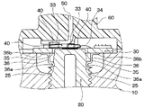
図1は、本実施形態における圧力センサ100の概略断面図である。この図に示されるように、圧力センサ100は、ハウジング10と、ステム20と、基板30と、バネターミナル40と、ターミナル50と、コネクタケース60とを備えて構成されている。
FIG. 1 is a schematic cross-sectional view of a
ハウジング10は、切削や冷間鍛造等により加工された中空形状の金属製のケースであり、その一端側の外周面には、被測定体にネジ結合可能なネジ部11が形成されている。ハウジング10の一端側には、ハウジング10の一端に形成された開口部12からハウジング10の他端側に延びる孔、すなわち圧力導入孔13が形成されており、この圧力導入孔13が圧力導入通路としての役割を果たす。また、ハウジング10は、ボディアースとしての役割を果たすものである。なお、このハウジング10は、本発明の金属ハウジングに相当する。
The
ステム20は、中空円筒形状に加工された金属製の部材であり、ステム20の外周部に設けられた雄ねじ部21が、ハウジング10の圧力導入孔13に形成された雌ねじ部14にネジ止めされてハウジング10内に収納されている。このステム20は、その軸の一端側にハウジング10に導入された圧力によって変形可能な薄肉状のダイヤフラム22を有し、軸の他端側にダイヤフラム22に繋がる通路23を有する。なお、このステム20は、本発明の金属ステムに相当する。
The
そして、通路23とハウジング10の圧力導入孔13とが連通された状態にされ、被測定体の圧力が圧力導入孔13からダイヤフラム22に伝えられるようになっている。
The
また、このステム20のダイヤフラム22上には、単結晶Si(シリコン)からなる圧力検出用のセンサチップ24が、低融点ガラスにより接合固定されている。このセンサチップ24は集積回路を有し、ステム20内部に導入された圧力によってダイヤフラム22が変形したとき、この変形に応じた抵抗値の変化を電気信号に変換して出力する検出部(歪みゲージ)として機能するものである。
On the
具体的には、ステム20内に導入された圧力によりダイヤフラム22が変形すると、これに応じてダイヤフラム22上に設置された歪みゲージが変形する。このとき、この変形によって歪みゲージを構成する素子の断面積が減少するので、歪みゲージの抵抗値が変化する。したがって、この抵抗値の変化を検出することにより歪みゲージに加えられた応力、すなわちステム20内に導入された圧力を検出することができる。そして、これらダイヤフラム22およびセンサチップ24が、圧力センサ100の基本性能を左右する。
Specifically, when the
基板30は、センサチップ24で検出された信号を外部出力するための信号に変換する機能を有するものである。具体的には、基板30は、センサチップ24から入力する信号を増幅するICチップ31と、圧力センサ100から出力される信号を圧力センサの仕様範囲内に調整するためのICチップ32と、圧力センサ100に入力するノイズを除去するためのチップコンデンサ33と、信号を処理する回路および配線パターンを備えたものである。センサチップ24と基板30とはワイヤ34でボンディングされて電気的に接続され、センサチップ24の信号が基板30に配置された回路および各ICチップ31、32に入力されるようになっている。
The
また、この基板30の裏面35にはバネ部36が設置されている。バネ部36は、基板30の回路とハウジング10とを電気的に接続するものであり、一枚の金属板で構成されている。そして、このバネ部36がハウジング10の内壁面15に設けられた凹部16に固定されることで、基板30がハウジング10に固定される。このバネ部36については、後で詳しく説明する。
A
なお、センサチップ24からの信号をワイヤ34で基板30に入力するために、センサチップ24の表面と基板30の表面との高さがほぼ等しくなるように基板30がハウジング10に設置される。
In order to input a signal from the
バネターミナル40は、基板30の回路とターミナル50とを電気的に接続するものであり、一枚の金属板の両側が折り曲げられてバネ状とされたものである。また、このバネターミナル40は、例えばリン青銅で形成されており、導電接着剤で基板30の電極が配置された位置に直接接着されている。そして、バネターミナル40のバネとされる部分がターミナル50に当接されることにより、基板30の回路とターミナル50との間で電気的な接続が可能になる。
The
また、このバネターミナル40は、本実施形態の圧力センサ100に用いられるターミナル50の数が後述するように3本であることから、3つのバネターミナル40が基板に設置されることとなる。そして、各バネターミナル40が各ターミナル50に電気的に接続されている。
Further, since the number of
ターミナル50は、L字状の棒状部材で構成されるものであり、コネクタケース60に設置されている。また、ターミナル50の下端部は平面形状になっており、上記バネターミナル40のバネとされる部分がこの下端部に当接するようになっている。本実施形態では、圧力センサ100を稼働するための電源用および接地用、そして信号出力用の3本のターミナル50がコネクタケース60に設置されている。そして、ターミナル50の先端部分が図示しない外部コネクタに接続されることで、自動車のECU等へ配線部材を介して電気的に接続される。
The terminal 50 is composed of an L-shaped rod-shaped member, and is installed in the
コネクタケース60は、圧力センサ100で検出された圧力値の信号を外部に出力するためのコネクタをなすものであり、樹脂等により形成されたものである。このコネクタケース60は、Oリング70を介してハウジング10の他端側にはめ込まれた状態で、ハウジング10の他端がコネクタケース60を押さえるようかしめ固定される。これにより、コネクタケース60はハウジング10と一体化してパッケージを構成し、該パッケージ内部のセンサチップ24、基板30、電気的接続部等を湿気・機械的外力より保護するようになっている。
The
次に、上記バネ部36について図2を参照して説明する。図2は、図1におけるバネ部36近傍を拡大した図である。
Next, the
図1および図2に示されるように、バネ部36は、基板30の裏面35に複数個設置されている。本実施形態では、少なくとも3つのバネ部36が基板30の裏面35に設置されることが望ましい。具体的には、3つのバネ部36は、基板30の裏面35の外縁部において、ハウジング10と基板30との組み付け中心軸を中心とした任意の半径を有する円の周方向にそれぞれ等間隔で接合される。
As shown in FIGS. 1 and 2, a plurality of
上述のように、各バネ部36は、一枚の金属板で構成されている。具体的には、金属板がプレス加工されて、金属板の一端側に引っ掛け部36a、他端側に曲げ部36bが設けられた構造になっている。本実施形態では、図2に示されるように、バネ部35の引っ掛け部36aは、湾曲形状、すなわち弓形状になっている。また、曲げ部36bは、金属板の他端側を折り曲げた形状になっている。
As described above, each
本実施形態では、バネ部36を構成する金属板の厚みは0.2〜0.5mmである。また、金属板には、導電性およびバネ性を有する材質のものが採用され、例えばリン青銅、ベリリウム銅、チタン銅等が用いられる。
In this embodiment, the thickness of the metal plate which comprises the
上記の構成を有するバネ部36は、基板30の裏面35に設置される。具体的には、図2に示されるように、バネ部36において、バネ部36の引っ掛け部36aをハウジング10の内壁面15に向けた状態で曲げ部36bを基板30の裏面35の所望の位置に設置する。この所望の位置には、基板30の回路と電気的に接続された図示しない電極が配置されており、この電極上にバネ部36の曲げ部36bが配置されるようになっている。そして、例えばはんだリフローによってバネ部36の曲げ部36bが基板30の裏面35の電極に電気的に接合される。
The
一方、ハウジング10の他端側の内壁面15には、その内壁面15の一部が凹んだ凹部16が設けられている。また、この凹部16は、基板30がハウジング10に設置されたときに、引っ掛け部36aがハウジング10の内壁面15に当接する位置に設けられている。
On the other hand, the
そして、基板30は次のようにハウジング10に設置される。すなわち、基板30をハウジングの他端側からハウジングに挿入すると、バネ部36の引っ掛け部36aがハウジング10の内壁面15の凹部16に当接する。このとき、バネ部36の引っ掛け部36aがハウジング10の凹部16によってステム20側に押されるため、バネ部36の有するバネ性、すなわちバネの弾性力によってバネ部36の引っ掛け部36aがハウジング10の凹部16を押しつけることとなる。
And the board |
このようにして、バネ部36の引っ掛け部36aがハウジング10の凹部16に固定され、基板30がハウジング10に設置される。また、バネ部36の引っ掛け部36aがハウジング10の凹部16を保持することで密着する。これにより、基板30の回路とハウジング10とがバネ部36を介して電気的に接続される。
In this manner, the
上記の構成を有する圧力センサ100では、圧力導入孔13から導入された圧力によってダイヤフラム22が歪むので、その歪みに応じた抵抗値を示す電気信号が基板30に出力される。そして、この電気信号が基板30の回路で出力信号に変換され、この出力信号が基板30の回路からバネターミナル40を介してターミナル50に出力されて、圧力が検出されるようになっている。
In the
また、基板30の回路においてグランドとされる電位がバネ部36を介してハウジング10と電気的に接続される。つまり、回路内のグランド電位を常に被測定体と同じ電位にすることができる。
Further, a potential that is grounded in the circuit of the
例えば圧力センサ100のターミナル50からノイズが入力する場合がある。このような場合に備えて、基板30の回路に配置されたグランド配線にチップコンデンサ33を接続しておき、そのチップコンデンサ33をバネ部36に電気的に接続しておく。これにより、基板30の回路に入力したノイズを、チップコンデンサ33およびバネ部36を介してハウジング10に出力することができる。また、基板30の回路のグランド電位とバネ部36とをチップコンデンサ33を介して電気的に接続することで、基板30の回路内のノイズをバネ部36およびハウジング10を介して被測定体に出力することができる。
For example, noise may be input from the
上記のように、バネ部36を介して基板30をハウジング10に固定する構造では、バネ部36の引っ掛け部36aをハウジング10の凹部16に挿入したときに、引っ掛け部36aがバネ部36のバネ性によってハウジング10の凹部16を押し込むことで、引っ掛け部36aをハウジング10の凹部16に確実に固定することができる。したがって、バネ部36の引っ掛け部36aをハウジング10の凹部16にはめ込むだけなので、バネ部36を介して基板30をハウジング10に容易に固定することができる。
As described above, in the structure in which the
また、各バネ部36は、基板30内に設けられた回路と電気的に接続されており、バネ部36の引っ掛け部36aがハウジング10の凹部16にバネ部36のバネ性によって密着していることから、バネ部36を介して基板30の回路とハウジング10とを電気的に接続することができる。
Each
本実施形態では、バネ部36の引っ掛け部36aおよびハウジング10の凹部16の形状を共通の湾曲形状としている。このように、引っ掛け部36aを固定する凹部16の形状を引っ掛け部36aと同じ湾曲形状とすることで、引っ掛け部36aの凹部16に対する当接面積を確保することができる。これにより、引っ掛け部36aを凹部16により確実に固定できる。したがって、基板30をより確実にハウジング10に固定できる。
In the present embodiment, the shape of the
(第2実施形態)
本実施形態では、第1実施形態と異なる部分についてのみ説明する。本実施形態では、バネ部の引っ掛け部がステムに形成された凹部に固定されていることが第1実施形態と異なる。なお、本実施形態では、上記第1実施形態と同じ構造のバネ部が用いられる。
(Second Embodiment)
In the present embodiment, only different parts from the first embodiment will be described. This embodiment is different from the first embodiment in that the hook portion of the spring portion is fixed to a concave portion formed in the stem. In the present embodiment, a spring portion having the same structure as that of the first embodiment is used.
図3は、本実施形態におけるバネ部36近傍を拡大した図である。この図に示されるように、ステム20の外壁面には、その外壁面の一部が凹んだ凹部25が形成されている。また、バネ部36においては、バネ部36の引っ掛け部36aがステム20側を向くように、バネ部36の曲げ部36bが基板30の裏面35の所望の位置に設置される。
FIG. 3 is an enlarged view of the vicinity of the
上記のようにバネ部36が基板30の裏面35に設置され、ステム20の外壁面に凹部25が形成された状態で、基板30は次のようにハウジングに固定される。すなわち、基板30をハウジング10に設置すると、バネ部35の引っ掛け部36aがステム20の凹部25に挿入される。このとき、バネ部36のバネ性によって引っ掛け部36aがステム20の凹部25を押さえつけることとなる。これにより、基板30をハウジング10に設置および固定できる。
In the state where the
このように、バネ部36の引っ掛け部36aをステム20に形成された凹部25に固定したとしても、基板30をハウジング10に固定することができる。また、基板30の回路をバネ部36およびステム20を介してハウジング10に電気的に接続することができる。このように、バネ部36をステム20に固定することによっても、第1実施形態と同様に、容易に基板30をハウジング10に固定でき、かつ、基板30の回路とハウジング10との電気的導通を図ることができる。
Thus, even if the
(他の実施形態)
バネ部36において、基板30と接合される曲げ部36bの形状は第1および第2実施形態の形状に限るものではない。図4は、バネ部36の曲げ部36bの一例を示した図である。この図に示されるように、バネ部36の曲げ部36bの先端部分の一部が折り曲げられて配線部36cが形成されている。そして、あらかじめ基板30の表面から裏面30に貫通する穴Hを形成しておき、この穴Hにバネ部36の配線部36cを挿入してバネ部36を基板30に設置する。このようにすることで、基板30の回路から基板30の裏面35に配線を配置する必要が無くなる。このように、バネ部36に配線の一部となる配線部36cを設けることもできる。同様に、引っ掛け部36aの形状も、第1および第2実施形態に限るものではない。
(Other embodiments)
In the
また、上記第1および第2実施形態では、バネ部36の数を3つとしていたが、バネ部36はこの数に限定されるものではない。
In the first and second embodiments, the number of
上記第1および第2実施形態では、はんだリフローによりバネ部36の曲げ部36bを基板30の裏面35に接合していたが、ろう材、例えば銀ろうによってバネ部36の曲げ部36bを基板30の裏面35に接合するようにしても良い。
In the first and second embodiments, the
10…ハウジング、20…ステム、30…基板、36…バネ部、
40…バネターミナル、50…ターミナル、60…コネクタケース。
DESCRIPTION OF
40 ... spring terminal, 50 ... terminal, 60 ... connector case.
Claims (6)
中空筒形状であって、この中空筒形状の軸の一端側に前記金属ハウジングに導入された圧力によって変形可能なダイヤフラム(22)を有し、前記軸の他端側に前記圧力導入孔と連通する通路(23)を有するステム(20)と、
前記ダイヤフラム上に設けられ、前記ダイヤフラムの変形に応じた電気信号を出力する検出部(24)と、
裏面(35)にバネ部(36)を有すると共に前記電気信号を受け取り、この電気信号に応じた出力信号を作成する回路を有する基板(30)と、
前記出力信号を外部に出力するターミナル(50)と、を備え、
前記金属ハウジングの他端側の内壁面(15)には、その内壁面が凹んだ凹部(16)が形成されており、
前記バネ部は、金属部材で構成されると共に、前記回路と電気的に接続される曲げ部(36b)と、前記金属ハウジングの前記凹部に当接する引っ掛け部(36a)とを有し、
前記金属ハウジングの前記凹部が、前記バネ部の弾性力によって前記バネ部の前記引っ掛け部に押さえつけられていることにより、前記回路が前記バネ部および前記金属ハウジングを通じて前記所定の電位に接続されるようになっていることを特徴とする圧力センサ。 A metal housing (10) having a pressure introduction hole (13) on one end side of the hollow shape and connected to a portion to be set at a predetermined potential;
A hollow cylindrical shape having a diaphragm (22) deformable by pressure introduced into the metal housing on one end side of the hollow cylindrical shaft, and communicating with the pressure introducing hole on the other end side of the shaft. A stem (20) having a passage (23) for
A detector (24) provided on the diaphragm and outputting an electrical signal corresponding to the deformation of the diaphragm;
A substrate (30) having a spring part (36) on the back surface (35) and having a circuit for receiving the electrical signal and creating an output signal in accordance with the electrical signal;
A terminal (50) for outputting the output signal to the outside,
The inner wall surface (15) on the other end side of the metal housing is formed with a recess (16) whose inner wall surface is recessed,
The spring portion is made of a metal member, and has a bent portion (36b) electrically connected to the circuit, and a hook portion (36a) that contacts the concave portion of the metal housing,
The concave portion of the metal housing is pressed against the hook portion of the spring portion by the elastic force of the spring portion, so that the circuit is connected to the predetermined potential through the spring portion and the metal housing. A pressure sensor characterized by
中空筒形状であって、この中空筒形状の軸の一端側に前記金属ハウジングに導入された圧力によって変形可能なダイヤフラム(22)を有し、前記軸の他端側に前記圧力導入孔と連通する通路(23)を有すると共に、前記金属ハウジングに直接固定される金属ステム(20)と、
前記ダイヤフラム上に設けられ、前記ダイヤフラムの変形に応じた電気信号を出力する検出部(24)と、
裏面(35)にバネ部(36)を有すると共に前記電気信号を受け取り、この電気信号に応じた出力信号を作成する回路を有する基板(30)と、
前記出力信号を外部に出力するターミナル(50)と、を備え、
前記金属ステムの外壁面においては、その外壁面が凹んだ凹部(25)が形成されており、
前記バネ部は、金属部材で構成されると共に、前記回路と電気的に接続される曲げ部(36b)と、前記金属ステムの前記凹部に当接する引っ掛け部(36a)とを有し、
前記金属ステムの前記凹部が、前記バネ部の弾性力によって前記バネ部の前記引っ掛け部に押さえつけられていることにより、前記回路が前記バネ部、前記金属ステムおよび前記金属ハウジングを通じて前記所定の電位に接続されるようになっていることを特徴とする圧力センサ。 A metal housing (10) which has a pressure introduction hole (13) and which is installed at a portion to be a predetermined potential;
A hollow cylindrical shape having a diaphragm (22) deformable by pressure introduced into the metal housing on one end side of the hollow cylindrical shaft, and communicating with the pressure introducing hole on the other end side of the shaft. A metal stem (20) having a passage (23) to be fixed and fixed directly to the metal housing;
A detector (24) provided on the diaphragm and outputting an electrical signal corresponding to the deformation of the diaphragm;
A substrate (30) having a spring part (36) on the back surface (35) and having a circuit for receiving the electrical signal and creating an output signal in accordance with the electrical signal;
A terminal (50) for outputting the output signal to the outside,
In the outer wall surface of the metal stem, a recess (25) in which the outer wall surface is recessed is formed,
The spring portion is formed of a metal member, and has a bent portion (36b) electrically connected to the circuit, and a hook portion (36a) that contacts the concave portion of the metal stem,
The concave portion of the metal stem is pressed against the hook portion of the spring portion by the elastic force of the spring portion, so that the circuit is brought to the predetermined potential through the spring portion, the metal stem, and the metal housing. A pressure sensor characterized by being connected.
中空筒形状であって、この中空筒形状の軸の一端側に前記金属ハウジングに導入された圧力によって変形可能なダイヤフラム(22)を有し、前記軸の他端側に前記圧力導入孔と連通する通路(23)を有するステム(20)と、
前記ダイヤフラム上に設けられ、前記ダイヤフラムの変形に応じた電気信号を出力する検出部(24)と、
裏面(35)にバネ部(36)を有すると共に前記電気信号を受け取り、この電気信号に応じた出力信号を作成する回路を有する基板(30)と、
前記出力信号を外部に出力するターミナル(50)と、を備える圧力センサの製造方法であって、
前記金属ハウジングとして、その他端側の内壁面(15)が凹んだ凹部(16)を有するものを用意する工程と、
金属部材であって、前記回路と電気的に接続する曲げ部(36b)と、前記金属ハウジングの前記凹部に当接する引っ掛け部(36a)とを有するバネ部(36)を用意する工程と、
前記バネ部において、前記曲げ部を前記基板の前記裏面の所望の位置に接合する工程と、
前記基板を前記金属ハウジングの前記他端側から前記一端側に差し込むと共に、前記バネ部の弾性力によって前記引っ掛け部を前記凹部に押しつける工程と、を有することを特徴とする圧力センサの製造方法。 A metal housing (10) having a pressure introduction hole (13) on one end side of the hollow shape and connected to a portion to be set at a predetermined potential;
A hollow cylindrical shape having a diaphragm (22) deformable by pressure introduced into the metal housing on one end side of the hollow cylindrical shaft, and communicating with the pressure introducing hole on the other end side of the shaft. A stem (20) having a passage (23) for
A detector (24) provided on the diaphragm and outputting an electrical signal corresponding to the deformation of the diaphragm;
A substrate (30) having a spring part (36) on the back surface (35) and having a circuit for receiving the electrical signal and creating an output signal in accordance with the electrical signal;
A terminal (50) for outputting the output signal to the outside, comprising:
Preparing the metal housing having a recess (16) with a recessed inner wall surface (15) on the other end side;
Preparing a spring part (36) which is a metal member and has a bent part (36b) electrically connected to the circuit and a hook part (36a) contacting the concave part of the metal housing;
In the spring portion, the step of joining the bent portion to a desired position on the back surface of the substrate;
A method of manufacturing a pressure sensor, comprising: inserting the substrate from the other end side of the metal housing to the one end side, and pressing the hook portion against the concave portion by an elastic force of the spring portion.
中空筒形状であって、この中空筒形状の軸の一端側に前記金属ハウジングに導入された圧力によって変形可能なダイヤフラム(22)を有し、前記軸の他端側に前記圧力導入孔と連通する通路(23)を有すると共に、前記金属ハウジングに直接固定される金属ステム(20)と、
前記ダイヤフラム上に設けられ、前記ダイヤフラムの変形に応じた電気信号を出力する検出部(24)と、
裏面(35)にバネ部(36)を有すると共に前記電気信号を受け取り、この電気信号に応じた出力信号を作成する回路を有する基板(30)と、
前記出力信号を外部に出力するターミナル(50)と、を備える圧力センサの製造方法であって、
前記金属ステムとして、その外壁面が凹んだ凹部(25)を有するものを用意する工程と、
金属部材であって、前記回路と電気的に接続する曲げ部(36b)と、前記金属ステムの前記凹部に当接する引っ掛け部(36a)とを有するバネ部(36)を用意する工程と、
前記バネ部において、前記曲げ部を前記基板の前記裏面の所望の位置に接合する工程と、
前記基板を前記金属ハウジングにおいて前記圧力導入孔が形成される側とは反対側から差し込むと共に、前記バネ部の弾性力によって前記引っ掛け部を前記金属ステムの前記凹部に押しつける工程と、を有することを特徴とする圧力センサの製造方法。 A metal housing (10) which has a pressure introduction hole (13) and which is installed at a portion to be a predetermined potential;
A hollow cylindrical shape having a diaphragm (22) deformable by pressure introduced into the metal housing on one end side of the hollow cylindrical shaft, and communicating with the pressure introducing hole on the other end side of the shaft. A metal stem (20) having a passage (23) to be fixed and fixed directly to the metal housing;
A detector (24) provided on the diaphragm and outputting an electrical signal corresponding to the deformation of the diaphragm;
A substrate (30) having a spring part (36) on the back surface (35) and having a circuit for receiving the electrical signal and creating an output signal in accordance with the electrical signal;
A terminal (50) for outputting the output signal to the outside, comprising:
Preparing a metal stem having a recess (25) whose outer wall surface is recessed;
Preparing a spring part (36) which is a metal member and has a bent part (36b) electrically connected to the circuit and a hook part (36a) contacting the concave part of the metal stem;
In the spring portion, the step of joining the bent portion to a desired position on the back surface of the substrate;
Inserting the substrate from the side opposite to the side where the pressure introduction hole is formed in the metal housing, and pressing the hooking portion against the concave portion of the metal stem by the elastic force of the spring portion. A method for manufacturing a pressure sensor.
Priority Applications (1)
| Application Number | Priority Date | Filing Date | Title |
|---|---|---|---|
| JP2004057644A JP2005249471A (en) | 2004-03-02 | 2004-03-02 | Pressure sensor and method for manufacturing the same |
Applications Claiming Priority (1)
| Application Number | Priority Date | Filing Date | Title |
|---|---|---|---|
| JP2004057644A JP2005249471A (en) | 2004-03-02 | 2004-03-02 | Pressure sensor and method for manufacturing the same |
Publications (1)
| Publication Number | Publication Date |
|---|---|
| JP2005249471A true JP2005249471A (en) | 2005-09-15 |
Family
ID=35030089
Family Applications (1)
| Application Number | Title | Priority Date | Filing Date |
|---|---|---|---|
| JP2004057644A Withdrawn JP2005249471A (en) | 2004-03-02 | 2004-03-02 | Pressure sensor and method for manufacturing the same |
Country Status (1)
| Country | Link |
|---|---|
| JP (1) | JP2005249471A (en) |
Cited By (2)
| Publication number | Priority date | Publication date | Assignee | Title |
|---|---|---|---|---|
| JP2013257237A (en) * | 2012-06-13 | 2013-12-26 | Denso Corp | Physical quantity detector |
| CN109990988A (en) * | 2017-12-29 | 2019-07-09 | 上海共联通信信息发展有限公司 | A kind of 4G wireless base station device board performance testing device |
-
2004
- 2004-03-02 JP JP2004057644A patent/JP2005249471A/en not_active Withdrawn
Cited By (3)
| Publication number | Priority date | Publication date | Assignee | Title |
|---|---|---|---|---|
| JP2013257237A (en) * | 2012-06-13 | 2013-12-26 | Denso Corp | Physical quantity detector |
| CN109990988A (en) * | 2017-12-29 | 2019-07-09 | 上海共联通信信息发展有限公司 | A kind of 4G wireless base station device board performance testing device |
| CN109990988B (en) * | 2017-12-29 | 2023-11-07 | 上海共联通信信息发展有限公司 | Board card performance testing device for 4G wireless base station equipment |
Similar Documents
| Publication | Publication Date | Title |
|---|---|---|
| EP1800098B1 (en) | System and method for pressure measurement | |
| JP4075776B2 (en) | Physical quantity sensor and pressure sensor | |
| US7114396B2 (en) | Pressure sensor | |
| EP1970686B1 (en) | Pressure sensor and manufacturing method of said sensor | |
| WO2013137432A1 (en) | Internal combustion engine fitted with combustion pressure detection device, and combustion pressure detection device | |
| US20050202729A1 (en) | Contact structure for connector array and electronic appliance having the same | |
| US20090095059A1 (en) | Pressure sensor and structure for attachment of pressure sensor | |
| JP2006250614A (en) | Pressure detector | |
| JP4118990B2 (en) | Pressure sensor | |
| US6619132B2 (en) | Sensor including a circuit lead frame and a terminal lead frame formed by a metal plate | |
| JP2009085723A (en) | Pressure detector and manufacturing method of same | |
| JP4534894B2 (en) | Pressure detection device | |
| JP2008185349A (en) | Pressure sensor | |
| JP2002333377A (en) | Pressure sensor | |
| JP2005249471A (en) | Pressure sensor and method for manufacturing the same | |
| JP4595747B2 (en) | Pressure sensor | |
| JP2002013997A (en) | Pressure sensor | |
| JP2008185334A (en) | Pressure sensor | |
| JP2008008829A (en) | Pressure sensor | |
| JP5893920B2 (en) | Detection system and detection device | |
| JP6554979B2 (en) | Pressure sensor | |
| JP2005172761A (en) | Pressure sensor | |
| JP2005351789A (en) | Manufacturing method for pressure detector | |
| JP2013096805A (en) | Dynamic quantity sensor | |
| JP4223273B2 (en) | Pressure sensor |
Legal Events
| Date | Code | Title | Description |
|---|---|---|---|
| A300 | Withdrawal of application because of no request for examination |
Free format text: JAPANESE INTERMEDIATE CODE: A300 Effective date: 20070605 |