JP2005248564A - Strut - Google Patents
Strut Download PDFInfo
- Publication number
- JP2005248564A JP2005248564A JP2004060622A JP2004060622A JP2005248564A JP 2005248564 A JP2005248564 A JP 2005248564A JP 2004060622 A JP2004060622 A JP 2004060622A JP 2004060622 A JP2004060622 A JP 2004060622A JP 2005248564 A JP2005248564 A JP 2005248564A
- Authority
- JP
- Japan
- Prior art keywords
- main body
- ground
- head
- column
- column main
- Prior art date
- Legal status (The legal status is an assumption and is not a legal conclusion. Google has not performed a legal analysis and makes no representation as to the accuracy of the status listed.)
- Granted
Links
- 238000012856 packing Methods 0.000 claims description 8
- 230000002093 peripheral effect Effects 0.000 claims description 7
- 239000000463 material Substances 0.000 claims description 5
- 230000000630 rising effect Effects 0.000 claims description 4
- 230000001174 ascending effect Effects 0.000 claims 1
- 239000004576 sand Substances 0.000 description 14
- 239000000428 dust Substances 0.000 description 13
- 238000000034 method Methods 0.000 description 4
- 239000002184 metal Substances 0.000 description 2
- 229920003002 synthetic resin Polymers 0.000 description 2
- 239000000057 synthetic resin Substances 0.000 description 2
- JOYRKODLDBILNP-UHFFFAOYSA-N Ethyl urethane Chemical compound CCOC(N)=O JOYRKODLDBILNP-UHFFFAOYSA-N 0.000 description 1
- 238000010586 diagram Methods 0.000 description 1
- 239000002994 raw material Substances 0.000 description 1
- 230000000717 retained effect Effects 0.000 description 1
Images
Landscapes
- Refuge Islands, Traffic Blockers, Or Guard Fence (AREA)
- Fencing (AREA)
Abstract
Description
本発明は、車止め等に使用する支柱に関するものである。 The present invention relates to a column used for a vehicle stop or the like.
従来、公園の入り口等に設置される車止めに使用される支柱として、支柱本体が地盤表面に対して出没可能なように昇降されるものがある。このような支柱は、近年バリアフリー等に対応すべく、支柱本体を埋没させたとき、支柱上の通行をより円滑に行うことができるように、支柱本体が地盤表面から突出しないことが求められている。かかる要求に対応するものとしては、図8、図9に示した構造を有するものが知られている。なお、図8は、支柱本体が地盤から突出した状態を示し、図9は、支柱本体が地盤内に埋没された状態を示したものである。 2. Description of the Related Art Conventionally, as a column used for a car stop installed at an entrance of a park or the like, there is a column that is lifted and lowered so that a column main body can appear and disappear from a ground surface. In order to cope with barrier-free etc. in recent years, such a column is required to prevent the column body from protruding from the ground surface so that when the column body is buried, the passage on the column can be performed more smoothly. ing. In order to meet such demands, those having the structures shown in FIGS. 8 and 9 are known. FIG. 8 shows a state in which the column main body protrudes from the ground, and FIG. 9 shows a state in which the column main body is buried in the ground.
この支柱1は、柱状に形成された支柱本体110と、埋設筒120と、案内筒130と、支持部材140とを備えている。
The
支柱本体110は、地盤Jに対して出没可能とすべく昇降可能に構成されているものであり、支柱頭部111から下端部112に至るまで、略同じ断面形状を有する筒状に形成され、支柱本体110の下部には、軸方向と垂直をなす方向に突出する突起113が形成されている。
The column
埋設筒120は、略同じ断面形状を有する筒状に形成されるとともに、その上端には、案内筒130を保持すべく内周側に向かって突出した案内筒保持部125が形成され、下部にはビス153を挿入するためのビス孔126が形成されている。そして、埋設筒120の全部分は、地盤J内に埋没される状態で地盤J内に埋設されている。
The buried
案内筒130は、埋設筒120内に挿入されるとともに支柱本体110に外嵌する本体部131と、本体部131の上端の形成されてボルト151により埋設筒120の案内筒保持部125上に固定される鍔部133とを備え、鍔部133の上面が地盤Jと略同じ高さとなる状態で地盤J内に埋設されている。
The
本体部131の下端には、前記突起113が入り込む案内溝135が形成され、この案内溝135は、本体部131の下端部分から軸方向に対して延設される縦溝部135aと、縦溝部135aの略先端部分から周方向に対して延設される横溝部135bと、横溝部135bの略先端部分から軸方向に対して延設される終端溝135cとを備えている。
A guide groove 135 into which the
支持部材140は、支柱本体110の下端部112が支持部材140の上端に当接することにより、支柱本体110が際限なく下降することを阻止するものであって、上端が閉口した筒状に形成されるともに、側面上部にビス153を挿入するためのビス孔141が形成され、埋設筒120の下部に挿入されている。そして、ビス孔126、141にビス153が挿入されることにより、支持部材140は埋設筒120に対し固定されている。
The
支柱1を構成する素材としては、一定の強度を保ちつつも全体の重量を軽量化すべく、支柱本体110、支持部材140、ボルト151、及び、ビス153には金属が使用され、埋設筒120には合成樹脂が使用されている。
As a material constituting the
また、支柱本体110を地盤J表面から突出させた状態で固定する場合、図8に図示したとおり、支柱本体110に備えられた突起113を、案内溝135の終端溝135cに係止させることにより行う。
Further, when the column
支柱本体110を、地盤Jの表面から突出した状態で固定された状態から、支柱本体110を地盤J内に埋没させる場合、以下の手順で行う。まず、支柱本体110を若干上昇させることにより突起113を終端溝135c内で上方にスライドさせる。次に、支柱本体110を回転させることにより縦溝部135aが配置されている方向に向けて突起113を横溝部135b内でスライドさせる。最後に、支柱本体110を下降させ、突起113を縦溝部135a内をスライドさせ、突起113を案内溝135から抜き出し、支柱本体110の下端部112を支持部材140の上端に当接させることにより、支柱本体110の支柱頭部111の上端が地盤J表面と略同じ高さとなる状態で、支柱本体110を地盤J内に埋没させる(図9参照)。
When the column
また、支柱本体110を、地盤J内に埋没させた状態から、支柱本体110が地盤Jの表面から突出した状態で固定された状態にする場合、以下の手順で行う。まず、支柱本体110を上昇させ、支柱本体110の突起113を縦溝部135a内で上方にスライドさせる。次に、支柱本体110を周方向に回転させ、終端溝135cが配置されている方向に向けて突起113を横溝部135b内でスライドさせる。最後に支柱本体110を若干下降させることで突起113を終端溝135cに入り込ませることにより、支柱本体110を地盤Jの表面から突出した状態で固定する。
Further, when the column
このような構成を採ると、支柱本体110は、地盤J内に完全に埋没させることが出来るため、支柱本体110を埋没させた際に地盤Jから突出する部分が存在せず、自動車、人などの通行をスムーズに行わせることが可能となる。
If such a configuration is adopted, the column
もっとも、支柱本体110を地盤J内に埋没させて、支柱本体110の下端部112を140の上端に当接させた場合において、この支柱1上を自動車、人等が通過する際、支柱本体110には上からの荷重が付加され、これに伴い支持部材140上にも上からの荷重が付加されることになる。かかる場合、支持部材140は埋設筒120に対しビス153によって固定されていることから、支柱本体110に付加される荷重は、支持部材140を介してビス153に伝達されることになり、結局はビス孔126、141に応力集中をもたらすことになる。さらに、支持部材140及びビス153は前述のとおり金属で形成されているのに対し、埋設筒120は前述のとおり合成樹脂で形成されているため、埋設筒120は、支持部材140及びビス153と比較して強度が低い。したがって、前述のような荷重が繰り返し付加されることにより埋設筒120のビス孔126が下に向かって拡がり、それに伴い、支持部材140が徐々に沈み込み、支柱本体110も徐々に沈み込む可能性が想定される。
However, when the column
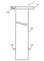
そこで、このような沈み込みを防止すべく、図10、図11に示した構造が考えられる(例えば、特許文献1)。図10は、支柱本体が地盤から突出した状態を示し、図11は、支柱本体が地盤内に埋没された状態を示したものである。 Therefore, in order to prevent such sinking, the structures shown in FIGS. 10 and 11 can be considered (for example, Patent Document 1). FIG. 10 shows a state in which the column main body protrudes from the ground, and FIG. 11 shows a state in which the column main body is buried in the ground.
なお、以下の説明において、前述の支柱1と同一の構成を有する部分については、同一符号を付するのみとし、その詳細な説明は省略する。
In addition, in the following description, about the part which has the same structure as the above-mentioned support |
この支柱1は、柱状に形成された支柱本体110と、埋設筒120と、案内筒130とを備えており、前記支持部材140は備えていない。
The
支柱本体110の頭部に供えられた支柱頭部111は、軸方向に対して垂直方向に突出する形状に形成されている。
The
埋設筒120の上端には、埋設筒120の本体部121の内径より大径であり、支柱頭部111を収納するための空間である頭部収納部123が形成されており、案内筒保持部125は形成されていない。
At the upper end of the buried
案内筒130は、前述のとおり、案内溝135を有する本体部131と鍔部133とを備えており、鍔部133は、頭部収納部123の底面123a上にボルト151によって固定されている。
As described above, the
支柱本体110を、地盤Jの表面から突出した状態で固定された状態から、支柱本体110を地盤J内に埋没させる場合、以下の手順で行う。まず、支柱本体110を若干上昇させることにより突起113を終端溝135c内で上方にスライドさせる。次に、支柱本体110を回転させることにより縦溝部135aが配置されている方向に向けて突起113を横溝部135b内でスライドさせる。最後に支柱本体110を下降させ、突起113を縦溝部135a内をスライドさせ、突起113を案内溝135から抜き出し、支柱本体110の支柱頭部111の下面を埋設筒120の頭部収納部123の底面123aに当接させ、支柱頭部111を頭部収納部123内に収納させることにより、支柱本体110全体を地盤J内に埋没させる(図11参照)。
When the column
なお、支柱本体110を地盤J内に埋没させた状態から、支柱本体110が地盤Jの表面から突出した状態で固定された状態にする手順は、前述の支柱1の場合と同一であるため、その説明を省略する。
In addition, since the procedure in which the column
かかる構成を採ると、支柱本体110の下降は、支柱頭部111の下面が頭部収納部123の底面123aに対し当接、すなわち面接触することにより阻止されるため、既述の従来技術のように、上からの荷重により、応力集中を起こすことがない。したがって、上からの荷重が繰り返し付加されることにより、支柱本体110が徐々に沈み込んでいくといった事態を避けることができ、前述の課題を解消することが可能となる。また、支柱本体110は、地盤J内に完全に埋没させることが出来るため、既述の従来技術と同様、支柱本体110を埋没させた際に地盤Jから突出する部分が存在せず、自動車、人などの通行をスムーズに行わせることが可能である。
しかしながら、前記の構造を採れば、図10のように、支柱本体110が地盤Jの表面から突出している場合、頭部収納部123が地盤Jの表面に対して凹む状態で外部空間に対して露出することになるため、砂、ゴミ等が頭部収納部123内に入り込みやすい。また、頭部収納部123内に砂、ゴミ等が入り込んだ場合、これらを除去しないと支柱頭部111を123内に円滑に収納することが困難となるが、頭部収納部123が地盤Jの表面に対して凹んでいるため、砂、ゴミ等を除去するのに手間がかかる。
However, if the above structure is adopted, as shown in FIG. 10, when the column
そこで、本発明は、支柱本体110が地盤Jの表面から露出している状態において、地盤Jから凹んだ部分に、砂、ゴミ等が入り込むことを阻止することにより、支柱本体110を地盤J内に円滑に埋没させることができる支柱を提供することを目的とする。
Therefore, the present invention prevents the sand
請求項1記載の発明は、地盤に対して出没可能とすべく昇降可能に構成された柱状の支柱本体と、全部分が地盤中に埋設され、前記支柱本体を収納する埋設筒とを有する支柱であって、前記支柱本体には、この支柱本体の軸方向に対して垂直方向に突出する頭部が備えられ、前記埋設筒の上端には、前記頭部を収納する頭部収納部が備えられ、前記頭部収納部の上方には、前記支柱本体が前記地盤から突出している際に、少なくとも一部分が前記地盤と同じ高さ又はそれ以上の高さに配置されて前記頭部収納部を隠蔽する隠蔽部材が備えられたことを特徴とする。
The invention according to
請求項2記載の発明は、請求項1記載の支柱において、前記隠蔽部材は、前記支柱本体が昇降するに伴って昇降するように構成されることにより、前記支柱本体の頭部が前記頭部収納部に収納されている際には、前記頭部の下面と前記頭部収納部の底面との間に配置される状態で、前記頭部収納部内に収納され、前記支柱本体が前記地盤から突出している際には、少なくとも一部分が前記地盤と同じ高さ又はそれ以上の高さに配置され、前記頭部収納部を隠蔽するように構成されたことを特徴とする。 According to a second aspect of the present invention, in the column according to the first aspect, the concealing member is configured to move up and down as the column main body moves up and down. When stored in the storage unit, the storage unit is stored in the head storage unit in a state of being disposed between the lower surface of the head unit and the bottom surface of the head storage unit, and the column main body is separated from the ground. When projecting, at least a portion is arranged at the same height as or higher than the ground, and is configured to conceal the head storage portion.
請求項3記載の発明は、請求項1又は2記載の支柱において、前記隠蔽部材は、前記支柱本体に外嵌する外嵌部と、この外嵌部の上端に形成された鍔部とを備え、この鍔部は、前記地盤と同じ高さ又はそれ以上の高さに配置された際、前記頭部収納部を隠蔽する形状に形成されたことを特徴とする。 According to a third aspect of the present invention, in the support column according to the first or second aspect, the concealing member includes an outer fitting portion that is fitted onto the column main body, and a flange portion that is formed at an upper end of the outer fitting portion. The saddle portion is characterized in that it is formed in a shape that conceals the head storage portion when it is disposed at the same height as or higher than the ground.
請求項4記載の発明は、請求項2又は3のいずれかに記載の支柱において、前記支柱本体には、この支柱本体が上昇する際、支柱本体が上昇端に達する前の所定上昇位置で前記隠蔽部材に係止して前記隠蔽部材を上昇させる係止部を備えたことを特徴とする。 According to a fourth aspect of the present invention, in the column according to any one of the second or third aspect, the column main body has a predetermined rising position before the column main body reaches the rising end when the column main body is raised. A locking portion that locks the concealing member to raise the concealing member is provided.
請求項5記載の発明は、請求項4記載の支柱において、前記係止部は、前記支柱本体に突起が形成されることにより構成されたことを特徴とする。 According to a fifth aspect of the present invention, in the support column according to the fourth aspect, the locking portion is configured by forming a protrusion on the main column body.
請求項6記載の発明は、請求項1〜5のいずれかに記載の支柱において、前記支柱本体の頭部の周縁部には、弾性力を有する素材で形成されたパッキン部材が備えられていることを特徴とする。
The invention according to claim 6 is the support according to any one of
請求項1記載の発明によれば、前記支柱本体の頭部を収納する頭部収納部は、前記支柱本体が前記地盤から突出している際には、前記隠蔽部材により隠蔽されているため、前記頭部収納部は、外部空間に対して直接露出することがなく、前記頭部収納部に、砂、ゴミ等が直接的に入り込むことが阻止される。 According to the first aspect of the present invention, the head storage portion that stores the head of the column main body is concealed by the concealing member when the column main body protrudes from the ground. The head storage portion is not directly exposed to the external space, and sand, dust and the like are prevented from directly entering the head storage portion.
さらに、前記隠蔽部材は、支柱本体が前記地盤から突出している際には、少なくとも一部分が前記地盤と同じ高さ又はそれ以上の高さに配置されているため、外部空間に露出している部分には、地盤表面に対して凹んだ部分が存在しないことになり、従来技術の構成と異なり、凹んだ部分に砂、ゴミ等が入り込むことがない。 Further, the concealing member is a portion exposed to the external space because at least a part of the concealing member is disposed at the same height as or higher than the ground when the column main body protrudes from the ground. Therefore, unlike the structure of the prior art, sand, dust or the like does not enter the recessed portion.
したがって、前記支柱本体を地盤内に埋没させる際、従来のように凹んだ部分に砂、ゴミ等を除去するのに手間を掛ける必要がなく、前記支柱本体を円滑に埋没させることが可能となる。 Therefore, when the column main body is buried in the ground, it is not necessary to take time and effort to remove sand, dust, etc. in the recessed portion as in the prior art, and the column main body can be buried smoothly. .
請求項2記載の発明によれば、前記隠蔽部材は、前記支柱本体の頭部が前記頭部収納部に収納されている際には、前記頭部の下面と前記頭部収納部の底面との間に配置された状態で前記頭部収納部内に収納されるため、前記頭部を頭部収納部に収納する際の障害とならない。また、前記支柱本体が前記地盤から突出している際には、少なくとも一部分が前記地盤と同じ高さ又はそれ以上の高さに配置されているため、前述のとおり、地盤表面に対して凹んでいる部分に、砂、ゴミ等が入り込むことがなく、前記支柱本体を円滑に埋没させることが可能となる。したがって、前記支柱本体をより円滑に地盤内に埋没させることが可能となる。 According to invention of Claim 2, when the head of the said support | pillar main body is accommodated in the said head accommodating part, the said concealing member is the bottom face of the said head, and the bottom face of the said head accommodating part. Since it is stored in the head storage part in a state of being disposed between the heads, it does not become an obstacle when the head is stored in the head storage part. In addition, when the column main body protrudes from the ground, at least a portion is disposed at the same height as or higher than the ground, and as described above, it is recessed with respect to the ground surface. It is possible to smoothly bury the column main body without sand, dust or the like entering the portion. Therefore, it becomes possible to bury the column main body more smoothly in the ground.
請求項3記載の発明によれば、前記支柱本体に外嵌する外嵌部と、この外嵌部の上端に形成された鍔部とを備えるように前記隠蔽部材を構成し、前記地盤と同じ高さ又はそれ以上の高さに配置された際、前記頭部収納部を隠蔽する形状に前記鍔部を形成するのみで、前記隠蔽部材を構成することが可能となるため、前記隠蔽部材の構成を簡素化することが可能となる。 According to invention of Claim 3, the said concealment member is comprised so that it may be provided with the external fitting part externally fitted to the said support | pillar main body, and the collar part formed in the upper end of this external fitting part, The same as the said ground Since the concealment member can be configured only by forming the collar portion in a shape concealing the head storage portion when arranged at a height or higher, the concealment member The configuration can be simplified.
請求項4記載の発明によれば、前記支柱本体に係止部を備えるだけで、支柱本体を上昇させるのに伴い前記隠蔽部材を上昇させることが可能となるため、支柱全体の構成を簡素化することが可能となる。 According to the fourth aspect of the present invention, the concealing member can be lifted as the column main body is raised only by providing the column main body with a locking portion, so that the configuration of the entire column is simplified. It becomes possible to do.
より具体的には、例えば請求項5のように前記支柱本体に突起を設けるのみで前記係止部を構成することが出来るため、支柱全体の構成を簡素化することが可能となる。 More specifically, for example, as described in claim 5, since the locking portion can be configured only by providing a protrusion on the column main body, the configuration of the entire column can be simplified.
請求項6記載の発明によれば、前記支柱本体の頭部の周縁部には、弾性力を有する素材で形成されたパッキン部材が備えられているため、前記頭部が前記頭部収納部内に収納されているときにおいて前記頭部で頭部収納部を完全に密閉することが出来、前記頭部収納部内に砂、ゴミ等が入り込むことを阻止することが可能となる。 According to invention of Claim 6, since the packing member formed with the raw material which has elastic force is provided in the peripheral part of the head of the said support | pillar main body, the said head is in the said head accommodating part. When the head is stored, the head storage portion can be completely sealed by the head, and sand, dust, etc. can be prevented from entering the head storage portion.
本発明の実施の形態につき、図1〜図7を用いて説明する。 An embodiment of the present invention will be described with reference to FIGS.
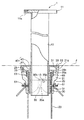
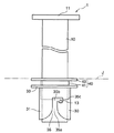
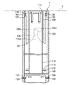
図1は、本実施形態の支柱において、支柱本体が地盤に対して突出した状態を示したものである。 FIG. 1 shows a state in which the column main body protrudes from the ground in the column according to this embodiment.
この支柱1は、図1に示すとおり、柱状に形成された支柱本体10と、埋設筒20と、案内筒30と、隠蔽部材40と、側面保護部材50とを備えている。
As shown in FIG. 1, the
支柱本体10は、地盤Jに対して出没可能とすべく昇降可能に構成されているものであり、図1、図3に示すとおり、支柱本体10の頭部に形成された支柱頭部11と、支柱本体10の下部において支柱本体10から軸方向と直角をなす方向に突出する突起13とを備えている。
The column
支柱頭部11は、この支柱本体10の軸方向に対して垂直方向に突出する状態で形成され、その上端の一部、周縁、及び、下端には、ゴム、ウレタン等のように弾力性を有する素材で形成されたパッキン部材11aが備えられている。
The
突起13は、支柱本体10の周縁に二箇所配置され、これらの突起13は、相互に対向するように配置されている。
The
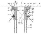
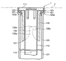
埋設筒20は、図1に示すとおり、その全部分が地盤J内に埋設され、本体部21と、本体部21より下部に配置された円筒部23とを備えている。本体部21の上端には、本体部21のその他の内径及び円筒部23の内径より大径となる頭部収納部25が形成されており、この頭部収納部25には、支柱頭部111が収納可能となっている。なお、本体部21及び円筒部23は、いずれもその内径は略同じ大きさであり、さらに、両部材は、ボルト61により一体となる状態で接続されている。
As shown in FIG. 1, the buried
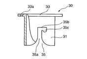
案内筒30は、図1、図3に示すとおり、埋設筒20の本体部21に挿入されるとともに、支柱本体10に外嵌する本体部31と、本体部31の上端に形成され、ボルト61を挿入するためのボルト穴33aを備えた鍔部33とを備えている。
As shown in FIGS. 1 and 3, the
本体部31の下端には、前記突起13が入り込む案内溝35が二箇所に形成されている。この案内溝35は、本体部31の下端部分から軸方向に対して延設される縦溝部35aと、縦溝部35aの略先端部分から周方向に対して延設される横溝部35bと、横溝部35bの略先端部分から軸方向に対して延設される終端溝35cとを、各々備えており、案内溝35同士は略対向する位置関係となっている。
At the lower end of the
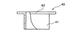
隠蔽部材40は、図1、図4に示すとおり、筒状に形成された本体部41(外嵌部に相当。)と、この本体部41の上端に形成された鍔部43とを備えている。
As shown in FIGS. 1 and 4, the concealing
本体部41は、その内周が支柱本体10の外周より若干大きい径に形成されるとともに、その外周は、本体部21及び円筒部23の内周より若干小さい径に形成されている。
The
鍔部43は、その外周が、側面保護部材50の本体部51(後述)の内周に略接触する形状に形成されている。
The outer periphery of the
側面保護部材50は、筒状に形成され、頭部収納部25の側面25bに配置される本体部51と、その上端に形成され、本体部21の上端21aに配置される鍔部53とを備えている。
The side
以下、図1及び図5を用いて、支柱本体10が地盤Jの表面から突出している状態についての各部材の配置状況につき説明する。
Hereinafter, with reference to FIG. 1 and FIG. 5, an arrangement state of each member in a state in which the column
支柱本体10は、突起13が、案内筒30の終端溝35cの下端に係止することにより、下方に移動することが阻止された状態で、案内筒30に対し固定されている。
The column
案内筒30は、前記本体部31が、埋設筒20の本体部21及び円筒部23の内周に配置され、前記鍔部33が、頭部収納部25の底面25aに接触した状態で配置されている。また、鍔部33は、ボルト穴33aに挿入されたボルト61により、頭部収納部25の底面25aに固定されている。
The
隠蔽部材40は、前記本体部41が支柱本体10に外嵌した状態で、埋設筒20内に配置されるとともに、鍔部43が案内筒30の鍔部33の上面に配置された状態で埋設筒20内に配置される。
The concealing
本体部41は、鍔部43が、案内筒30の鍔部33の上面に略接触する高さと地盤Jの表面と略同じ高さに位置する高さとの間を移動可能とする状態で、本体部21及び円筒部23の内周に挿入されている。
The
また、本体部41の下端部は支柱本体10の突起13に係止されており、この突起13により、隠蔽部材40の鍔部43は、地盤Jの表面と略同じ高さに位置する状態に保持されている。
Further, the lower end portion of the
そして、前述のとおり、鍔部43は、その外周が側面保護部材50の本体部51(後述)の内周に略接触する形状に形成されているため、頭部収納部25は、鍔部43によって外部空間から隠蔽されている。
And as above-mentioned, since the outer periphery of the
以下、支柱本体10が地盤Jの表面から突出している状態から支柱本体10の全体を地盤J内に埋没させる状態にするための動作につき説明する。
Hereinafter, an operation for changing the column
まず、支柱本体10を若干上昇させることにより突起13を終端溝35c内で上方にスライドさせる。これに伴い、隠蔽部材40は若干上昇する。
First, the column
次に、支柱本体10を回転させることにより縦溝部35aが配置されている方向に向けて突起13を横溝部35b内でスライドさせる。
Next, by rotating the column
さらに支柱本体10を下降させることにより、突起13を縦溝部35a内をスライドさせ、隠蔽部材40を、鍔部43が案内筒30の鍔部33に当接する位置まで下降させる。またさらに、支柱本体10の下降を継続させることにより、突起13を案内溝35から抜き出し、支柱本体10の支柱頭部11を埋設筒20の頭部収納部25内に収納することにより、支柱本体10全体を地盤J内に埋没させる。
Further, by lowering the column
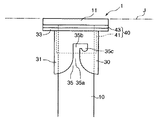
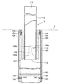
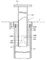
かかる状態では、支柱頭部11及び隠蔽部材40は、図6、図7に示すように、支柱頭部11は、パッキン部材11a下端が隠蔽部材40の鍔部43に接触し、その周縁が側面保護部材50の本体部51に接触する状態で配置されている。そして、かかる状態で配置されることにより、頭部収納部25は、支柱頭部11によって隠蔽されている。また、隠蔽部材40は、その鍔部43の下面が案内筒30の鍔部33の上面に接触する状態で配置されている。
In this state, as shown in FIGS. 6 and 7, the
さらに、支柱本体10が地盤J内に埋没させた状態から、支柱本体10が地盤Jの表面から突出した状態にするための動作につき説明する。
Furthermore, an operation for changing the column
まず、支柱本体10を上昇させ、支柱本体10の突起13を案内溝35の縦溝部35aに嵌め込み、縦溝部35a内で突起13を上方にスライドさせ、突起13を隠蔽部材40の本体部41の下端に係止させる。さらに、横溝部35bが形成されている高さ(上昇端に相当。)に突起13が位置する高さまで、支柱本体10の上昇を継続することにより、隠蔽部材40を上昇させる。
First, the column
次に、支柱本体10を周方向に回転させ、終端溝35cが配置されている方向に向けて突起13を横溝部35b内でスライドさせる。最後に支柱本体10を若干下降させることにより突起13を終端溝35cに入り込ませることにより、支柱本体10を地盤Jの表面から突出した状態で固定する。なお、かかる動作により隠蔽部材40は若干下降する。
Next, the column
以上の構成を採れば、支柱本体10が地盤Jの表面から突出した状態においては、支柱本体10の支柱頭部11を収納する頭部収納部25は、隠蔽部材40の鍔部43により隠蔽されているため、頭部収納部25は、外部空間に対して直接露出することがなく、頭部収納部25に、砂、ゴミ等が直接的に入り込むことが阻止される。さらに、隠蔽部材40の鍔部43は、地盤Jの表面と略同じ高さに配置されているため、外部空間に露出する部分には、地盤Jの表面に対して凹んだ部分が存在しないことになり、従来技術の構成と異なり、凹んだ部分に砂、ゴミ等が入り込むことがない。
With the above configuration, in a state where the column
したがって、支柱本体10を地盤J内部に埋没させる際、従来のように凹んだ部分に砂、ゴミ等を除去するのに手間を掛ける必要がなく、支柱本体10を円滑に埋没させることが可能となる。
Therefore, when the column
さらに、隠蔽部材40は、支柱本体10の支柱頭部11が頭部収納部25に収納されている際には、支柱頭部11の下面と頭部収納部25の底面との間に配置された状態で頭部収納部25内に収納されるため、支柱頭部11を頭部収納部25内に収納する際の障害とならない。したがって、支柱本体10をより円滑に地盤J内に埋没させることが可能となる。
Further, the concealing
また、隠蔽部材40を、支柱本体10に外嵌する本体部41と、この本体部41の上端に形成された鍔部43とを備えるように構成し、鍔部43を、外周が側面保護部材50の本体部51の内周に略接触する形状に形成することのみで、鍔部43を地盤と同じ高さに配置した際には、頭部収納部25を隠蔽することが可能となるため、隠蔽部材40の構成を簡素化することが可能となる。
Further, the concealing
さらに、支柱本体10に突起13を備えるだけで、支柱本体10を上昇させるのに伴い隠蔽部材40を上昇させることが可能となるため、支柱1の構成を簡素化することが可能となる。
Furthermore, since the concealing
また、支柱本体10の支柱頭部11の下端及び周縁には、弾性力を有する素材で形成されたパッキン部材11aが備えられているため、支柱頭部11が頭部収納部25内に収納されているときにおいて、支柱頭部11で頭部収納部25を完全に密閉することが出来、頭部収納部25内に砂、ゴミ等が入り込むことを阻止することが可能となる。
In addition, since the packing
さらに、支柱本体10が地盤J表面から突出した状態においては、支柱頭部11にパッキン部材11aが備えられていることから、人等が誤って支柱頭部11に接触した場合においても、その衝撃を和らげることが可能となる。
Further, in the state where the column
なお、隠蔽部材40の鍔部43は、支柱本体10を地盤J表面から突出させた状態において、必ずしも地盤Jと略同じ高さに配置する必要はない。たとえば、隠蔽部材40に、鍔部43の外周部分から下方に延びる補助部を形成し、鍔部43を地盤Jの表面より若干上方に配置し、側面保護部材50の本体部51の内周面と前記補助部とを接触させることにより、外部空間に対して露出する部分に、地盤Jの表面に対して凹んだ部分が存在しないように支柱1を構成することが可能である。
In addition, the
また、本体部21と円筒部23とは、別々の部材で構成する必要はなく、初めから一体となるように形成してもよい。
Further, the
1 支柱
10 支柱本体
11a パッキン部材
11 支柱頭部
13 突起
20 埋設筒
21a 上端
21 本体部
23 円筒部
25 頭部収納部
25a 底面
40 隠蔽部材
41 本体部(外嵌部)
43 鍔部
DESCRIPTION OF
43
Claims (6)
前記支柱本体には、この支柱本体の軸方向に対して垂直方向に突出する頭部が備えられ、
前記埋設筒の上端には、前記頭部を収納する頭部収納部が備えられ、
前記頭部収納部の上方には、前記支柱本体が前記地盤から突出している際に、少なくとも一部分が前記地盤と同じ高さ又はそれ以上の高さに配置されて前記頭部収納部を隠蔽する隠蔽部材が備えられた
ことを特徴とする支柱。 A columnar columnar body configured to be movable up and down to be able to appear and disappear with respect to the ground, and a column having an embedded cylinder in which all parts are embedded in the ground and store the columnar body,
The column main body is provided with a head protruding in a direction perpendicular to the axial direction of the column main body,
At the upper end of the buried cylinder, a head storage part for storing the head is provided,
Above the head storage part, when the column main body protrudes from the ground, at least a part thereof is arranged at the same height as or higher than the ground to conceal the head storage part. A support column provided with a concealing member.
前記隠蔽部材は、前記支柱本体が昇降するに伴って昇降するように構成されることにより、
前記支柱本体の頭部が前記頭部収納部に収納されている際には、前記頭部の下面と前記頭部収納部の底面との間に配置される状態で、前記頭部収納部内に収納され、
前記支柱本体が前記地盤から突出している際には、少なくとも一部分が前記地盤と同じ高さ又はそれ以上の高さに配置され、前記頭部収納部を隠蔽するように構成された
ことを特徴とする支柱。 The strut according to claim 1,
The concealing member is configured to move up and down as the column main body moves up and down,
When the head of the column main body is stored in the head storage, the head is stored in the head storage in a state of being arranged between the lower surface of the head and the bottom of the head storage. Stowed,
When the column main body protrudes from the ground, at least a portion is arranged at the same height as or higher than the ground, and is configured to conceal the head storage portion. Prop to do.
前記隠蔽部材は、前記支柱本体に外嵌する外嵌部と、この外嵌部の上端に形成された鍔部とを備え、
この鍔部は、前記地盤と同じ高さ又はそれ以上の高さに配置された際、前記頭部収納部を隠蔽する形状に形成された
ことを特徴とする支柱。 The strut according to claim 1 or 2,
The concealing member includes an outer fitting portion that is fitted onto the column main body, and a flange portion that is formed at the upper end of the outer fitting portion,
The strut is formed in a shape that conceals the head storage portion when it is disposed at the same height as or higher than the ground.
前記支柱本体には、この支柱本体が上昇する際、支柱本体が上昇端に達する前の所定上昇位置で前記隠蔽部材に係止して前記隠蔽部材を上昇させる係止部を備えた
ことを特徴とする支柱。 In the support | pillar in any one of Claim 2 or 3,
The support body is provided with an engaging portion that engages the concealing member and raises the concealing member at a predetermined ascending position before the prop body reaches the rising end when the support body rises. The prop.
前記係止部は、前記支柱本体に突起が形成されることにより構成された
ことを特徴とする支柱。 The strut according to claim 4,
The said locking part was comprised by forming a protrusion in the said support | pillar main body. The support | pillar characterized by the above-mentioned.
前記支柱本体の頭部の周縁部には、弾性力を有する素材で形成されたパッキン部材が備えられている
ことを特徴とする支柱。 In the support | pillar in any one of Claims 1-5,
A support column comprising a packing member formed of a material having elasticity in a peripheral portion of a head portion of the support column main body.
Priority Applications (1)
| Application Number | Priority Date | Filing Date | Title |
|---|---|---|---|
| JP2004060622A JP4262617B2 (en) | 2004-03-04 | 2004-03-04 | Prop |
Applications Claiming Priority (1)
| Application Number | Priority Date | Filing Date | Title |
|---|---|---|---|
| JP2004060622A JP4262617B2 (en) | 2004-03-04 | 2004-03-04 | Prop |
Publications (2)
| Publication Number | Publication Date |
|---|---|
| JP2005248564A true JP2005248564A (en) | 2005-09-15 |
| JP4262617B2 JP4262617B2 (en) | 2009-05-13 |
Family
ID=35029307
Family Applications (1)
| Application Number | Title | Priority Date | Filing Date |
|---|---|---|---|
| JP2004060622A Expired - Fee Related JP4262617B2 (en) | 2004-03-04 | 2004-03-04 | Prop |
Country Status (1)
| Country | Link |
|---|---|
| JP (1) | JP4262617B2 (en) |
Cited By (3)
| Publication number | Priority date | Publication date | Assignee | Title |
|---|---|---|---|---|
| JP2013127166A (en) * | 2011-12-19 | 2013-06-27 | Sekisui Jushi Co Ltd | Installation structure of elastic columnar body |
| KR101314909B1 (en) | 2012-12-10 | 2013-10-04 | 박재선 | Fence for transport rail of coal storage yard |
| CN104878710A (en) * | 2015-06-26 | 2015-09-02 | 盐城工学院 | Guide rod device used for preventing collision at traffic intersection |
Families Citing this family (1)
| Publication number | Priority date | Publication date | Assignee | Title |
|---|---|---|---|---|
| CN109372326A (en) * | 2018-12-13 | 2019-02-22 | 国网黑龙江省电力有限公司检修公司 | Outdoor deep buried hydraulic lift safety fence pole and its arrangement method |
-
2004
- 2004-03-04 JP JP2004060622A patent/JP4262617B2/en not_active Expired - Fee Related
Cited By (4)
| Publication number | Priority date | Publication date | Assignee | Title |
|---|---|---|---|---|
| JP2013127166A (en) * | 2011-12-19 | 2013-06-27 | Sekisui Jushi Co Ltd | Installation structure of elastic columnar body |
| KR101314909B1 (en) | 2012-12-10 | 2013-10-04 | 박재선 | Fence for transport rail of coal storage yard |
| CN104878710A (en) * | 2015-06-26 | 2015-09-02 | 盐城工学院 | Guide rod device used for preventing collision at traffic intersection |
| CN104878710B (en) * | 2015-06-26 | 2017-03-15 | 盐城工学院 | The guide rod device that collides is prevented for traffic intersection |
Also Published As
| Publication number | Publication date |
|---|---|
| JP4262617B2 (en) | 2009-05-13 |
Similar Documents
| Publication | Publication Date | Title |
|---|---|---|
| US10451131B2 (en) | Shock-absorbing device | |
| JP4262617B2 (en) | Prop | |
| US20140203583A1 (en) | Vehicle door beltline molding | |
| JP4097622B2 (en) | Intrusion control device | |
| JP4365400B2 (en) | Auxiliary contact unit of magnetic contactor | |
| JP5182785B2 (en) | Pump container | |
| JP2007014395A (en) | Adjustable shock cushion cane | |
| US8047341B2 (en) | Cylinder apparatus | |
| JP2008148931A (en) | Bathtub installation structure and method for repairing devices on lower side of bathtub | |
| KR200384373Y1 (en) | Auto Locking Apparatus for Container of Trailer | |
| CN107444304A (en) | A kind of automobile protective box structure | |
| JP2006138075A (en) | Nosing member | |
| KR102843591B1 (en) | Console device | |
| JP3977709B2 (en) | Prop support device | |
| JP2009214970A (en) | Lift for vehicle maintenance | |
| JP4048381B2 (en) | Retractable entry prevention device | |
| CN2707826Y (en) | Anti-theft well head device and its unlocking tool | |
| JP2005226368A (en) | Top-railed sliding door device | |
| KR100552272B1 (en) | Manual winding pop-up monitor for car | |
| JPS6361532B2 (en) | ||
| KR102634402B1 (en) | Run up type swing out door retainer structures | |
| JP4809009B2 (en) | Suspension lower swing device | |
| JPH0316376Y2 (en) | ||
| KR200303407Y1 (en) | Case for spare key of car | |
| KR20250116481A (en) | Foundation cover device for ground equipment for distribution |
Legal Events
| Date | Code | Title | Description |
|---|---|---|---|
| A621 | Written request for application examination |
Free format text: JAPANESE INTERMEDIATE CODE: A621 Effective date: 20070115 |
|
| A131 | Notification of reasons for refusal |
Free format text: JAPANESE INTERMEDIATE CODE: A131 Effective date: 20081111 |
|
| A521 | Written amendment |
Free format text: JAPANESE INTERMEDIATE CODE: A523 Effective date: 20090108 |
|
| TRDD | Decision of grant or rejection written | ||
| A01 | Written decision to grant a patent or to grant a registration (utility model) |
Free format text: JAPANESE INTERMEDIATE CODE: A01 Effective date: 20090203 |
|
| A01 | Written decision to grant a patent or to grant a registration (utility model) |
Free format text: JAPANESE INTERMEDIATE CODE: A01 |
|
| A61 | First payment of annual fees (during grant procedure) |
Free format text: JAPANESE INTERMEDIATE CODE: A61 Effective date: 20090209 |
|
| FPAY | Renewal fee payment (event date is renewal date of database) |
Free format text: PAYMENT UNTIL: 20120220 Year of fee payment: 3 |
|
| R150 | Certificate of patent or registration of utility model |
Free format text: JAPANESE INTERMEDIATE CODE: R150 |
|
| FPAY | Renewal fee payment (event date is renewal date of database) |
Free format text: PAYMENT UNTIL: 20130220 Year of fee payment: 4 |
|
| FPAY | Renewal fee payment (event date is renewal date of database) |
Free format text: PAYMENT UNTIL: 20140220 Year of fee payment: 5 |
|
| R250 | Receipt of annual fees |
Free format text: JAPANESE INTERMEDIATE CODE: R250 |
|
| R250 | Receipt of annual fees |
Free format text: JAPANESE INTERMEDIATE CODE: R250 |
|
| R250 | Receipt of annual fees |
Free format text: JAPANESE INTERMEDIATE CODE: R250 |
|
| R250 | Receipt of annual fees |
Free format text: JAPANESE INTERMEDIATE CODE: R250 |
|
| LAPS | Cancellation because of no payment of annual fees |