JP2005248043A - Composition for antireflection film and coating method using the same - Google Patents
Composition for antireflection film and coating method using the same Download PDFInfo
- Publication number
- JP2005248043A JP2005248043A JP2004061566A JP2004061566A JP2005248043A JP 2005248043 A JP2005248043 A JP 2005248043A JP 2004061566 A JP2004061566 A JP 2004061566A JP 2004061566 A JP2004061566 A JP 2004061566A JP 2005248043 A JP2005248043 A JP 2005248043A
- Authority
- JP
- Japan
- Prior art keywords
- coating
- composition
- substrate
- solvent
- thin film
- Prior art date
- Legal status (The legal status is an assumption and is not a legal conclusion. Google has not performed a legal analysis and makes no representation as to the accuracy of the status listed.)
- Withdrawn
Links
Images
Landscapes
- Application Of Or Painting With Fluid Materials (AREA)
- Paints Or Removers (AREA)
Abstract
Description
本発明は、ダイコート法を用いて基板上に反射防止膜を形成する際に使用する反射防止膜用組成物及び該反射防止用組成物を用いた塗工方法に関する。 The present invention relates to an antireflection film composition used when an antireflection film is formed on a substrate using a die coating method, and a coating method using the antireflection composition.
近年、細隙を有したノズルを用いて、毛細管現象を利用したダイコート法による成膜方法が検討されている。この成膜方法では、塗工時にノズルをシート状または板状の基板近傍に位置させ、ノズルに設けられた細隙から塗工液を基板に接液させるとともに、ノズルと基板との間に間隙(以下、塗工ギャップと記す)を形成しながら基板表面に塗工液を塗工するものである(特許文献1参照)。
近年、反射防止膜を形成させる基板は、ガラス基板に代わり、プラスチック等の樹脂基板が多くなっている。このような樹脂基板は軽量化や取り扱いの容易さ等、ガラス基板に対して有利な点が多いが、樹脂の特性上、ガラス基板に比べ基板の厚さムラが発生しやすい。このためノズルと基板との間の塗工ギャップが狭いとノズルが基板に接触しやすくなり、塗工に影響を及ぼしてしまう。また、ノズルと基板との接触を避けるために塗工ギャップを広くすることも可能であるが、塗工ギャップが広いと塗工液の接液状態が切れやすくなる。このため、塗工ギャップを広くしつつ塗工速度を上げることは困難であった。
本発明は、上記従来技術の問題点に鑑み、塗工速度を抑えることなく塗工ギャップを広げることもできる反射防止膜用組成物及び該組成物を用いた塗工方法を提供することを技術課題とする。
In recent years, as a substrate on which an antireflection film is formed, a resin substrate such as a plastic is increasing instead of a glass substrate. Although such a resin substrate has many advantages over the glass substrate such as weight reduction and ease of handling, the thickness of the substrate is more likely to be uneven than the glass substrate due to the characteristics of the resin. For this reason, when the coating gap between the nozzle and the substrate is narrow, the nozzle easily comes into contact with the substrate, which affects the coating. Further, it is possible to widen the coating gap in order to avoid contact between the nozzle and the substrate. However, if the coating gap is wide, the liquid contact state of the coating liquid tends to be cut off. For this reason, it has been difficult to increase the coating speed while widening the coating gap.
In view of the above-mentioned problems of the prior art, the present invention provides a composition for an antireflection film that can widen a coating gap without suppressing a coating speed, and a coating method using the composition. Let it be an issue.
(1) ダイコート法を用いて塗工ギャップを400μm以上且つ塗工速度3m/min以上の塗工速度にて薄膜を形成するのに適した反射防止膜用組成物において、該反射防止膜用組成物は少なくともUV硬化樹脂と、金属酸化物と、硬化剤と、1種類以上の溶媒とを含有するとともに、該含有している1種類以上からなる溶媒の20℃における蒸気圧が0.3kPa以上3.5kPa以下、且つ前記含有している溶媒の20℃における粘度が0.3mPa・s以上2.6mPa・s以下であることを特徴とする。
(2) (1)の反射防止膜用組成物において、前記溶媒は極性溶媒であることを特徴とする。
(3) (2)の反射防止用組成物において、前記溶媒はアルコール類またはケトン類、またはエステル類であることを特徴とする。
(4) (3)の反射防止膜用組成物において、前記UV硬化樹脂としてジペンタエリスリトールヘキサアクリレートを用いることを特徴とする。
(5) 塗工ノズルと基板との間に間隙を有しつつ該塗工ノズル先端から出る塗工液を基板に接液させた状態にて相対的に基板を移動させることによって基板上に薄膜を形成する塗工方法おいて、塗工速度を1m/min以上5m/min以下とするとともに塗工時における前記間隙を400μm以上600μm以下として前記基板に塗工を行う場合に、該塗工時に用いる前記塗工液に含有する溶媒の蒸気圧を0.3kPa以上3.5kPa以下、且つ溶媒の粘度を0.5mPa・s以上2.5mPa・s以下とすることを特徴とする。
(1) An antireflection film composition suitable for forming a thin film using a die coating method at a coating gap of 400 μm or more and a coating speed of 3 m / min or more. The product contains at least a UV curable resin, a metal oxide, a curing agent, and one or more types of solvent, and the vapor pressure at 20 ° C. of the solvent including the one or more types is 0.3 kPa or higher. The viscosity at 20 ° C. of the contained solvent is not less than 3.5 kPa and not more than 2.6 mPa · s.
(2) In the composition for antireflection film of (1), the solvent is a polar solvent.
(3) In the antireflective composition of (2), the solvent is an alcohol, a ketone, or an ester.
(4) The antireflective film composition according to (3), wherein dipentaerythritol hexaacrylate is used as the UV curable resin.
(5) A thin film is formed on the substrate by moving the substrate relatively with the coating liquid coming out from the tip of the coating nozzle in contact with the substrate while having a gap between the coating nozzle and the substrate. In the coating method for forming the substrate, when the coating speed is 1 m / min or more and 5 m / min or less and the gap is 400 μm or more and 600 μm or less during coating, The vapor pressure of the solvent contained in the coating solution used is 0.3 kPa to 3.5 kPa, and the viscosity of the solvent is 0.5 mPa · s to 2.5 mPa · s.
本発明によれば、塗工装置と基板との接触を抑制するとともに塗工速度を抑えることなく反射防止膜を基板に形成することができる。 ADVANTAGE OF THE INVENTION According to this invention, an antireflection film can be formed in a board | substrate, without suppressing a contact with a coating apparatus and a board | substrate, and suppressing a coating speed.
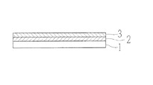
本発明の実施の形態について図面を基に説明する。図1は本実施の形態で示すダイコート法を用いた塗工装置により製造される光学薄膜付透明基板の概略構成を示す図である。図1に示す光学薄膜付透明基板は、2層の薄膜層から構成され反射防止効果を有するものである。 Embodiments of the present invention will be described with reference to the drawings. FIG. 1 is a diagram showing a schematic configuration of a transparent substrate with an optical thin film manufactured by a coating apparatus using a die coating method shown in the present embodiment. The transparent substrate with an optical thin film shown in FIG. 1 is composed of two thin film layers and has an antireflection effect.
1は透明の基板(基材)である。使用する基板の屈折率は1.48〜1.70程度のものを使用する。具体的に、基板材料としてはガラス、プラスチック(例えば、ポリカーボネイト樹脂、ポリエステル樹脂、ポリウレタン樹脂、アクリル樹脂等)が用いられ、光学的に透明であれば特に限定されない。なお、ここで言う基板とは、板状の基板以外にもシート状の基材も含むものとしている。
2は基板1上に積層され、基板1の屈折率よりも高い屈折率をもつ第1薄膜層である。第1薄膜層2に使用される材料は、使用する基板1に応じて適宜選択されるが、屈折率1.50〜2.50程度の範囲のものが使用される。具体的に第1薄膜層2の主成分には、ZrO2(屈折率1.9)や、TiO2(屈折率2.2)等の金属酸化物が挙げられる。また、第1薄膜層2の膜厚は、所望する反射防止効果が得られるために必要な膜厚であればよい。例えばλ=500nm〜600nm程度の波長において反射率が最小になるように膜厚を設定する場合には、光学膜厚(nd)は好ましくは100nm〜200nm程度、さらに好ましくは、125nm〜200nm程度であれば良い。
3は第1薄膜層2上に積層され、第1薄膜層2の屈折率よりも低い屈折率をもつ第2薄膜層である。第2薄膜層3に使用される材料は、屈折率1.35〜1.60程度の範囲のものが使用される。具体的に第2薄膜層3の主成分にはSiO2(屈折率1.46)等の金属酸化物が挙げられる。また、第2薄膜層3の膜厚は、所望する反射防止効果が得られるために必要な膜厚であればよい。例えば500nm〜600nm程度の波長において反射率が最小になるように膜厚を設定する場合には、光学膜厚(nd)は好ましくは100nm〜200nm程度、さらに好ましくは、100nm〜150nm程度であれば良い。
また、本実施形態では、基板上に2層の薄膜を形成して反射防止効果を得るものとしているが、これに限るものではなく、所望する光学特性が得られるように適宜積層する薄膜層の数を決定すればよい。また、基板上に形成する膜厚は上記に示した膜厚に限るものではなく、所望する光学特性に応じて適宜決定すればよい。
Reference numeral 3 denotes a second thin film layer which is laminated on the first
In this embodiment, two layers of thin films are formed on the substrate to obtain an antireflection effect. However, the present invention is not limited to this, and thin film layers that are appropriately stacked so as to obtain desired optical characteristics can be obtained. What is necessary is just to determine a number. Further, the film thickness formed on the substrate is not limited to the above-described film thickness, and may be appropriately determined according to desired optical characteristics.
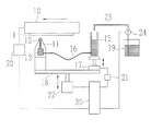
図2は本実施の形態で用いる反射防止膜用組成物を塗工液として用いた塗工装置を側方から見たときの概略図を示す。
10は下面に複数の吸引孔を有した移動台であり、この吸引孔からの吸引によって基板1を移動台10の下面に保持するようになっている。移動台10はモータ等からなる駆動手段20によって、塗工装置の前後方向(紙面右から左)に駆動可能となっている。11は塗工ノズルであり、基板1の横幅と同じか、それよりも長く塗工装置の左右方向に延びている。塗工ノズル11の先端には、ノズル11内部に向かって形成されている細隙12が設けられており、後述する反射防止膜用組成物(以下、塗工液と記す)が、この細隙12を経て基板1に塗工されるようになっている。13は細隙12に繋がる液溜部である。
FIG. 2 is a schematic view of a coating apparatus using the composition for an antireflective film used in the present embodiment as a coating liquid, when viewed from the side.
図2に示す15は、液溜部13に供給管16を介して塗工液を供給する液供給部である。液供給部15は、駆動手段21によって上下動する載置台17上に固定保持されている。また、塗工ノズル11及び液供給部15を載置する載置台17は、駆動手段22によって上下動する台18上に固定保持されている。
図2に示す19は塗工液を貯蔵する液貯蔵部である。液貯蔵部19には液供給部15に塗工液を送るための供給管23が接続されており、ポンプ24の駆動により液貯蔵部19内に貯蔵された塗工液が液供給部15に送られるようになっている。なお、液供給部15内の塗工液の量は、液供給部15に溜まっている塗工液の液面高さを検出する図示なきセンサによって検出され、この検出結果に基に液貯蔵部19から塗工液の供給が行われるため、常に基準量以上の液量が確保される。
30は塗工装置の駆動制御を行う制御部であり、駆動手段20〜22、ポンプ24等が接続されている。
次に、本実施形態で用いる反射防止膜用組成物について説明する。
本実施形態における反射防止膜用組成物は、UV(紫外線)硬化樹脂、金属酸化物、硬化剤(重合開始剤)、溶媒からなる。UV硬化樹脂としては、その化学構造に架橋点を複数有する樹脂が用いられ、例えば多官能アクリレート、多官能メタクリレートや多官能ウレタンアクリレート等が好適に用いられる。具体的に多官能アクリレートとしては、ジペンタエリスリトールヘキサアクリレート(DPHA)、ペンタエリスリトールテトラアクリレートやペンタエリスリトールトリアクリレート等が挙げられる。また、多官能メタクリレートとしては、トリメチロールプロパントリメタクリレート、グリセリンジメタクリレート、等が挙げられる。また、多官能ウレタンアクリレートとしては、ヘ゜ンタエリストリールトリアクリレートトリレンシ゛イソシアネートウレタンホ゜リマーや、ヘ゜ンタエリストリールトリアクリレートイソホロンシ゛イソシアネートウレタンホ゜リマー等が挙げられる。また、この他にもグリシジルメタクリレート等の単官能モノマーを適宜加えても良い。単官能モノマーは反応性希釈剤として用いられる。このようなUV硬化樹脂は反射防止膜用組成物全体において、好ましくは0.1重量%以上10.0重量%以下、さらに好ましくは0.5重量%以上5.0重量%以下程度、配合することができる。
Next, the antireflection film composition used in the present embodiment will be described.
The composition for an antireflective film in this embodiment comprises a UV (ultraviolet) curable resin, a metal oxide, a curing agent (polymerization initiator), and a solvent. As the UV curable resin, a resin having a plurality of crosslinking points in its chemical structure is used. For example, polyfunctional acrylate, polyfunctional methacrylate, polyfunctional urethane acrylate, or the like is preferably used. Specific examples of the polyfunctional acrylate include dipentaerythritol hexaacrylate (DPHA), pentaerythritol tetraacrylate, and pentaerythritol triacrylate. Examples of the polyfunctional methacrylate include trimethylolpropane trimethacrylate, glycerin dimethacrylate, and the like. Examples of the polyfunctional urethane acrylates include hexane ester reel triacrylate tri-isocyanate urethane polymer, hexane ester reel triacrylate isophorone isocyanate urethane polymer, and the like. In addition, a monofunctional monomer such as glycidyl methacrylate may be added as appropriate. Monofunctional monomers are used as reactive diluents. Such a UV curable resin is preferably blended in an amount of 0.1% by weight or more and 10.0% by weight or less, more preferably 0.5% by weight or more and 5.0% by weight or less in the entire composition for antireflection film. be able to.
また、屈折率調整剤として用いる金属酸化物は、高屈折率用材料としてはTiO2ゾルやZrO2スラリー(その他として、ITO、ATO、ZnO、SnO2、CeOの各スラリー)を用いることができる。また、低屈折率用材料としては、SiO2ゾルを用いることができる。このような金属酸化物は、反射防止膜用組成物全体において、好ましくは0.5重量%以上10.0重量%以下、さらに好ましくは1.0重量%以上5.0重量%以下程度配合することができる。金属酸化物の含有量をこのような範囲内にすることにより、膜設計時に設定した各薄膜層の屈折率にすることができる。
硬化剤(重合開始剤)としては、アミノケトン系の光重合開始剤を好適に用いることができる。具体的には2-メチル-1[4-(メチルチオ)フェニル]-2-モルフォリノフ゜ロハ゜ン-1-オン等を挙げることができる。なお硬化剤は、UV硬化樹脂を完全に重合、硬化させることができるだけの量が配合されていればよい。
As the metal oxide used as the refractive index adjusting agent, TiO 2 sol and ZrO 2 slurry (in addition, ITO, ATO, ZnO, SnO 2 , and CeO slurries) can be used as the high refractive index material. . As the low refractive index material, SiO 2 sol can be used. Such a metal oxide is preferably blended in an amount of about 0.5 wt% to 10.0 wt%, more preferably about 1.0 wt% to 5.0 wt% in the entire composition for an antireflection film. be able to. By setting the content of the metal oxide within such a range, the refractive index of each thin film layer set at the time of film design can be obtained.
As the curing agent (polymerization initiator), an aminoketone-based photopolymerization initiator can be suitably used. Specific examples include 2-methyl-1 [4- (methylthio) phenyl] -2-morpholinofluoro-1-one. In addition, the hardening | curing agent should just contain the quantity which can fully superpose | polymerize and harden UV curable resin.
本実施形態の反射防止膜用組成物に用いる溶媒は、基板上に塗膜後、蒸発させて除去することになる。このため、生産効率の観点からはできるだけ早く除去するためには、溶媒の蒸気圧が高い(言い換えると沸点は低い)方が好ましい。しかしながら本発明者らは、溶媒の蒸気圧が高すぎると、塗工が不安定になり、また、溶媒の蒸気圧が低い場合には、塗工は安定して行うことができるが、乾燥ムラが顕著になることを見出した。本発明者らは鋭意研究の結果、本実施形態の反射防止膜用組成物(塗工液)に用いる溶媒の蒸気圧は、好ましくは0.3kPa以上3.5kPa以下、さらに好ましくは0.5kPa以上3.0kPa以下であることが判明した。溶媒の蒸気圧が0.3kPa未満の場合、溶媒の除去に時間がかかるとともに、乾燥ムラが生じる。また、溶媒の蒸気圧が3.5kPaを超えると、塗工時に流れ方向に沿ってスジが発生し易くなる。 The solvent used in the composition for an antireflective film of this embodiment is removed by evaporation after coating on the substrate. For this reason, from the viewpoint of production efficiency, in order to remove as soon as possible, it is preferable that the vapor pressure of the solvent is high (in other words, the boiling point is low). However, the present inventors have found that when the vapor pressure of the solvent is too high, the coating becomes unstable, and when the vapor pressure of the solvent is low, the coating can be performed stably, but the drying unevenness Was found to be prominent. As a result of intensive studies, the inventors of the present invention preferably have a vapor pressure of the solvent used for the composition for antireflection film (coating liquid) of the present embodiment of 0.3 kPa to 3.5 kPa, more preferably 0.5 kPa. It was found to be 3.0 kPa or less. When the vapor pressure of the solvent is less than 0.3 kPa, it takes time to remove the solvent and uneven drying occurs. If the vapor pressure of the solvent exceeds 3.5 kPa, streaks are likely to occur along the flow direction during coating.
また、溶媒の粘度は、20℃において好ましくは0.3mPa・s以上2.6mPa・s以下であり、さらに好ましくは0.5mPa・s以上2.5mPa・s以下である。溶媒の粘度が2.6mPa・sを超えると、塗工ノズルの細隙12を塗工液が毛細管現象によって昇り難くなり、塗工ギャップを400μm以上600μm以下程度、塗工速度を3m/min以上5m/min以下として塗工を行った場合に、塗工液が基板の移動に追従できず、途中で切れてしまう可能性がある。
具体的には、例えば極性溶媒としては、n−ブタノール、イソブタノール、イソプロピルアルコール、エチルセロソルブ等のアルコール類、メチルイソブチルケトン(MIBK)等のケトン類、フ゜ロヒ゜レンク゛リコールモノメチルエーテル等のエーテル類、酢酸ブチル等のエステル類、非極性溶媒としてはトルエン、キシレン等を好適に用いることができる。
Further, the viscosity of the solvent at 20 ° C. is preferably 0.3 mPa · s or more and 2.6 mPa · s or less, more preferably 0.5 mPa · s or more and 2.5 mPa · s or less. When the viscosity of the solvent exceeds 2.6 mPa · s, it becomes difficult for the coating liquid to rise due to the capillary phenomenon in the
Specifically, for example, polar solvents include alcohols such as n-butanol, isobutanol, isopropyl alcohol, ethyl cellosolve, ketones such as methyl isobutyl ketone (MIBK), ethers such as fluoropolyethylene monomethyl ether, butyl acetate As the esters and the nonpolar solvent, toluene, xylene and the like can be preferably used.
このような溶媒を用いて上述した蒸気圧及び粘度の範囲内となるように、溶媒を単体または混合して用いればよい。なお、上述した溶媒以外の溶媒であっても、単体または2種類以上を混合することにより、混合溶媒の蒸気圧及び粘度が上述した範囲であれば好適に用いることができる。このような溶媒は、反射防止膜用組成物全体に対して、好ましくは80重量%以上99.9重量%以下、さらに好ましくは90重量%以上99重量%以下である。 Using such a solvent, the solvent may be used alone or in combination so as to be within the above-described vapor pressure and viscosity ranges. In addition, even if it is a solvent other than the solvent mentioned above, it can use suitably, if the vapor pressure and viscosity of a mixed solvent are the ranges mentioned above by mixing a single type or two or more types. Such a solvent is preferably 80% by weight or more and 99.9% by weight or less, more preferably 90% by weight or more and 99% by weight or less, with respect to the entire composition for an antireflection film.
上述した材料を用いて反射防止膜用組成物を得る場合には、所定量の溶媒中にUV硬化樹脂を適量入れて所定時間攪拌し、得られた混合液中にさらに硬化剤を適量入れた後、所定時間攪拌する。この混合液にさらに金属酸化物(ゾルまたはスラリー)を適量を入れ攪拌した後、ろ過(例えば、0.5μmのガラスフィルタ)をして粒径の大きなものを除外することにより、反射防止膜用組成物の完成となる。 In the case of obtaining an antireflection film composition using the above-mentioned materials, an appropriate amount of UV curable resin was put in a predetermined amount of solvent and stirred for a predetermined time, and an appropriate amount of a curing agent was further added to the obtained mixed liquid. Then, the mixture is stirred for a predetermined time. An appropriate amount of a metal oxide (sol or slurry) is added to this mixed solution and stirred, and then filtered (for example, a 0.5 μm glass filter) to exclude large-diameter particles. The product is completed.
次に、前述した塗工装置及び反射防止膜用組成物(塗工液)を用いて基板に薄膜を形成する方法を以下に説明する。
基板1は予め超音波等を用いてドライクリーニングが行われ、表面の塵等が取り除かれた後、移動台10の吸引により、塗工予定面が下側に向いた状態にて移動台10に固定保持される。制御部30は、塗工ノズル11の先端と液供給部15の液面とが所定の位置関係となるように駆動手段21、22を駆動させて載置台14及び17を上下動させる。塗工時における塗工ノズル11の先端の高さ位置に対して、液供給部15の液面高さが若干低くなるように、載置台14及び載置台17の高さ位置を調整することにより、塗工ノズル11の液溜部13内の塗工液は、毛細管現象によって細隙11を通り、塗工ノズル11の先端まで上昇する。
Next, a method for forming a thin film on a substrate using the coating apparatus and the antireflection film composition (coating liquid) described above will be described below.
The
次に、制御部30は駆動手段22を駆動させて台18を上昇させ、塗工ノズル11と液供給部15とを一体的に上昇させる。制御部30は移動台10に吸着されている基板1の下面(塗工開始位置)に塗工ノズル11の先端に表れている塗工液を接液させた後、所望する膜厚が得られるように基板1の塗工面と塗工ノズル11先端との間隔(塗工ギャップ)を調整する。本実施形態では塗工ギャップを400μm以上600μm以下程度にする。この程度の塗工ギャップを有していれば、基板1の肉厚精度のバラツキによる基板1と塗工ノズル11との接触を避けることができる。
Next, the
基板1下面への塗工液の接液後、制御部30は駆動手段20を用いて移動台10を塗工開始位置から塗工終了位置へ移動させる。このときの塗工速度は、例えば3.0m/min以上5.0m/minの範囲で、所望する薄膜の膜厚が得られる塗工速度に設定する。塗工速度が3.0m/min未満(例えば1m/min)であっても良いが、生産効率は低下する。また、5.0m/minより速い速度の場合、本実施形態で設定する塗工ギャップの範囲では、塗工液が液切れすることなく追従するのが困難となる。
After the coating liquid contacts the lower surface of the
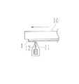
図4に示すように、移動台10が所定速度(例えば3m/min)で移動することにより、塗工ノズル11の先端の塗工液は、基板1の下面に所定の厚さをもって塗工されることとなる。なお、基板1に塗工される塗工液は、細隙12の形状によって生じる毛細管現象によって液溜部13から塗工ノズル11先端に常に一定量が供給され、液溜部13は液供給部15から塗工液が供給管16を介して常に供給されている。
As shown in FIG. 4, when the movable table 10 moves at a predetermined speed (for example, 3 m / min), the coating liquid at the tip of the
塗工開始位置から塗工終了位置まで移動台10が移動したら、制御部30は駆動手段22を用いて台18を下降させて基材1の下面から塗工液を離液させる。塗工液の離液後、基板1を図示なき減圧機内に入れ、所定時間減圧することにより、塗工液に用いた溶媒を完全に蒸発(除去)させる。溶媒除去後、基材1表面に紫外線を所定時間照射し、塗膜を硬化処理して、第1薄膜層の形成完了となる。基板1上に第1薄膜層を形成後、塗工液を第2薄膜層(低屈折率層)用の塗工液に変えて同様の操作を行い、第2薄膜層を形成し、反射防止膜を基板1上に形成する。
When the moving table 10 moves from the coating start position to the coating end position, the
次に、具体的な実施例等について以下に説明する。
実施例1〜10、比較例1〜6では、高屈折率用の反射防止膜用組成物(塗工液)について示す。
Next, specific examples and the like will be described below.
Examples 1 to 10 and Comparative Examples 1 to 6 show the antireflective film composition (coating liquid) for high refractive index.
<実施例1>
実施例1に用いる塗工液は、溶媒としてn−ブタノールを全体の76.5重量%、及びメチルイソブチルケトン(MIBK)を全体の20重量%とし、UV硬化樹脂であるジペンタエリスリトールヘキサアクリレート(DPHA)を全体の0.78重量%、及びグリシジルメタクリレートを全体の0.09重量%、硬化剤であるイルガキュア907(チハ゛ スヘ゜シャルティ ケミカルス゛(株)製 含有量5重量%-イソフ゜ロヒ゜ルアルコール溶液)を0.04重量%、ZrO2スラリ−を2.59重量%として、十分に攪拌し、高屈折率用の塗工液とした。
得られた塗工液を図2に示した塗工装置の液貯蔵部19に入れた後、ポンプ24、供給管23を用いて液貯蔵部19から液供給部15に所定量入れる。なお、液供給部15に入れられた塗工液は、供給管16を介して塗工ノズル11の液溜部13に供給される。
図2に示した塗工装置において、塗工速度3.5m/min、塗工ギャップは500μmとなるように調節し、前述した塗工方法にてプラスチック基板に塗工を行った。塗工の際に塗工ノズル11と基板1との接触や、塗工液が塗工中に液切れすることはなかった。塗工済の基板を減圧機に入れ、20秒かけて10Paまで減圧して溶媒を除去した。溶媒除去後、基材を減圧機から取り出し、紫外線照射を行って硬化処理した。
得られた薄膜付基板を(株)島津製作所製 分光光度計 UV-2400PCにて測定し、得られたピーク波長より光学膜厚を求めたところ、nd=190nmとなり、所望する膜厚が得られていた。また、厚さムラや乾燥ムラ等による外観不良は見当たらなかった。以上の結果を表1に示す。表1では、基板1上に形成された薄膜を目視にて観察し、乾燥ムラ等による外観不良がなければ○、外観不良が生じていれば×とした。また、塗工開始から塗工終了まで液が途中で切れずに追従できていれば○、液切れが生じていれば×とした。なお、表1中の組成物における各材料の数値はすべて重量%、また、表1中の蒸気圧及び粘度は、溶媒の添加比率を基に20℃における混合溶媒の粘度の値(ただし、少数点以下第3位を四捨五入)を表している。
<Example 1>
The coating liquid used in Example 1 is composed of 76.5% by weight of n-butanol as a solvent and 20% by weight of methyl isobutyl ketone (MIBK), and dipentaerythritol hexaacrylate (DPHA), which is a UV curable resin. 0.78% by weight of total, 0.09% by weight of glycidyl methacrylate, 0.04% by weight of Irgacure 907 (a content of 5% by weight from Chiba Specialty Chemicals Co., Ltd.), a ZrO 2 slurry Was 2.59% by weight and sufficiently stirred to obtain a coating solution for high refractive index.
After the obtained coating liquid is put into the
In the coating apparatus shown in FIG. 2, the coating speed was adjusted to 3.5 m / min and the coating gap was adjusted to 500 μm, and coating was performed on the plastic substrate by the coating method described above. During coating, contact between the coating
The obtained substrate with a thin film was measured with a spectrophotometer UV-2400PC manufactured by Shimadzu Corporation. When the optical film thickness was determined from the obtained peak wavelength, nd = 190 nm was obtained, and the desired film thickness was obtained. It was. Further, no appearance defect due to thickness unevenness, drying unevenness or the like was found. The results are shown in Table 1. In Table 1, the thin film formed on the
<実施例2>
実施例1の組成に対し、溶媒をn−ブタノール66.5重量%、メチルイソブチルケトン(MIBK)を30重量%とした以外は、全て実施例1と同条件とし、高屈折率用の反射防止膜用組成物を得た。得られた反射防止膜用組成物を用いて、実施例1同様の条件にて基板1上に高屈折率を有する薄膜を形成した。得られた薄膜の光学膜厚ndを実施例1同様に求めたところ190nmであり、所望する膜厚が得られていた。また、液切れ、外観不良は見当たらなかった。以上の結果を表1に示す。
<Example 2>
Except for the composition of Example 1, the solvent was 66.5% by weight and methyl isobutyl ketone (MIBK) was 30% by weight. A composition was obtained. A thin film having a high refractive index was formed on the
<実施例3>
実施例1の組成に対し、溶媒をn−ブタノール46.5重量%、メチルイソブチルケトン(MIBK)50重量%とした以外は、全て実施例1と同条件とし、高屈折率用の反射防止膜用組成物を得た。得られた反射防止膜用組成物を用いて、実施例1同様の条件にて基板1上に高屈折率を有する薄膜を形成した。得られた薄膜の光学膜厚ndを実施例1同様に求めたところ190nmであり、所望する膜厚が得られていた。また、液切れ、外観不良は見当たらなかった。以上の結果を表1に示す。
<Example 3>
The composition for Example 1 was the same as Example 1 except that the solvent was 46.5% by weight of n-butanol and 50% by weight of methyl isobutyl ketone (MIBK). I got a thing. A thin film having a high refractive index was formed on the
<実施例4>
実施例1の組成に対し、溶媒をメチルイソブチルケトン(MIBK)96.5重量%とした以外は、全て実施例1と同条件とし、高屈折率用の反射防止膜用組成物を得た。得られた反射防止膜用組成物を用いて、実施例1同様の条件にて基板1上に高屈折率を有する薄膜を形成した。得られた薄膜の光学膜厚ndを実施例1同様に求めたところ190nmであり、所望する膜厚が得られていた。また、液切れ、外観不良は見当たらなかった。以上の結果を表1に示す。
<Example 4>
The antireflective film composition for high refractive index was obtained under the same conditions as in Example 1 except that the solvent was changed to 96.5% by weight of methyl isobutyl ketone (MIBK) with respect to the composition of Example 1. A thin film having a high refractive index was formed on the
<実施例5>
実施例1の組成に対し、溶媒をn−ブタノール76.5重量%、酢酸ブチル20重量%とした以外は、全て実施例1と同条件とし、高屈折率用の反射防止膜用組成物を得た。得られた反射防止膜用組成物を用いて、実施例1同様の条件にて基板1上に高屈折率を有する薄膜を形成した。得られた薄膜の光学膜厚ndを実施例1同様に求めたところ190nmであり、所望する膜厚が得られていた。また、液切れ、外観不良は見当たらなかった。以上の結果を表1に示す。
<Example 5>
The composition for Example 1 was the same as Example 1 except that the solvent was changed to 76.5% by weight of n-butanol and 20% by weight of butyl acetate, and an antireflective film composition for high refractive index was obtained. . A thin film having a high refractive index was formed on the
<実施例6>
実施例1の組成に対し、溶媒をn−ブタノール46.5重量%、酢酸ブチル50重量%とした以外は、全て実施例1と同条件とし、高屈折率用の反射防止膜用組成物を得た。得られた反射防止膜用組成物を用いて、実施例1同様の条件にて基板1上に高屈折率を有する薄膜を形成した。得られた薄膜の光学膜厚ndを実施例1同様に求めたところ190nmであり、所望する膜厚が得られていた。また、液切れ、外観不良は見当たらなかった。以上の結果を表1に示す。
<Example 6>
The composition for Example 1 was the same as Example 1 except that the solvent was 46.5% by weight of n-butanol and 50% by weight of butyl acetate, and an antireflective film composition for high refractive index was obtained. . A thin film having a high refractive index was formed on the
<実施例7>
実施例1の組成に対し、溶媒を酢酸ブチル96.5重量%とした以外は、全て実施例1と同条件とし、高屈折率用の反射防止膜用組成物を得た。得られた反射防止膜用組成物を用いて、実施例1同様の条件にて基板1上に高屈折率を有する薄膜を形成した。得られた薄膜の光学膜厚ndを実施例1同様に求めたところ190nmであり、所望する膜厚が得られていた。また、液切れ、外観不良は見当たらなかった。以上の結果を表1に示す。
<Example 7>
The antireflective film composition for high refractive index was obtained under the same conditions as in Example 1 except that the solvent was 96.5% by weight with respect to the composition of Example 1. A thin film having a high refractive index was formed on the
<実施例8>
実施例1の組成に対し、溶媒をn−ブタノール46.5重量%、フ゜ロヒ゜レンク゛リコールモノメチルエーテル50重量%とした以外は、全て実施例1と同条件とし、高屈折率用の反射防止膜用組成物を得た。得られた反射防止膜用組成物を用いて、実施例1同様の条件にて基板1上に高屈折率を有する薄膜を形成した。得られた薄膜の光学膜厚ndを実施例1同様に求めたところ190nmであり、所望する膜厚が得られていた。また、液切れ、外観不良は見当たらなかった。以上の結果を表1に示す。
<Example 8>
The antireflective coating composition for high refractive index was the same as in Example 1, except that the solvent was 46.5% by weight of n-butanol and 50% by weight of fluoropolyethylene monomethyl ether with respect to the composition of Example 1. Obtained. A thin film having a high refractive index was formed on the
<実施例9>
実施例1の組成に対し、溶媒をn−ブタノール46.5重量%、トルエン50重量%とした以外は、全て実施例1と同条件とし、高屈折率用の反射防止膜用組成物を得た。得られた反射防止膜用組成物を用いて、実施例1同様の条件にて基板1上に高屈折率を有する薄膜を形成した。得られた薄膜の光学膜厚ndを実施例1同様に求めたところ190nmであり、所望する膜厚が得られていた。また、液切れ、外観不良は見当たらなかった。以上の結果を表1に示す。
<Example 9>
The composition for Example 1 was the same as Example 1 except that the solvent was changed to 46.5% by weight of n-butanol and 50% by weight of toluene to obtain a composition for an antireflective film for high refractive index. A thin film having a high refractive index was formed on the
<実施例10>
実施例1の組成に対し、溶媒をn−ブタノール46.5重量%、キシレン50重量%とした以外は、全て実施例1と同条件とし、高屈折率用の反射防止膜用組成物を得た。得られた反射防止膜用組成物を用いて、実施例1同様の条件にて基板1上に高屈折率を有する薄膜を形成した。得られた薄膜の光学膜厚ndを実施例1同様に求めたところ190nmであり、所望する膜厚が得られていた。また、液切れ、外観不良は見当たらなかった。以上の結果を表1に示す。
<Example 10>
The antireflective film composition for high refractive index was obtained under the same conditions as in Example 1 except that the solvent was changed to 46.5% by weight of n-butanol and 50% by weight of xylene with respect to the composition of Example 1. A thin film having a high refractive index was formed on the
<比較例1>
実施例1の組成に対し、溶媒をn−ブタノール96.5重量%とした以外は、全て実施例1と同条件とし、高屈折率用の反射防止膜用組成物を得た。得られた反射防止膜用組成物を用いて、実施例1同様の条件にて基板1上に高屈折率を有する薄膜を形成した。得られた薄膜の光学膜厚ndを実施例1同様に求めたところ190nmであり、所望する膜厚が得られていた。また、乾燥ムラ等による外観不良は見当たらなかったものの、液切れが発生した。以上の結果を表1に示す。
<Comparative Example 1>
The composition for Example 1 was the same as Example 1 except that the solvent was 96.5% by weight of n-butanol, and an antireflective film composition for high refractive index was obtained. A thin film having a high refractive index was formed on the
<比較例2>
実施例1の組成に対し、溶媒をn−ブタノール86.5重量%、メチルイソブチルケトン(MIBK)を10重量%とした以外は、全て実施例1と同条件とし、高屈折率用の反射防止膜用組成物を得た。得られた反射防止膜用組成物を用いて、実施例1同様の条件にて基板1上に高屈折率を有する薄膜を形成した。得られた薄膜の光学膜厚ndを実施例1同様に求めたところ190nmであり、所望する膜厚が得られていた。また、乾燥ムラ等による外観不良は見当たらなかったものの、液切れが発生した。以上の結果を表1に示す。
<Comparative example 2>
For the antireflective film for high refractive index except that the composition of Example 1 is 86.5% by weight of n-butanol and 10% by weight of methyl isobutyl ketone (MIBK). A composition was obtained. A thin film having a high refractive index was formed on the
<比較例3>
実施例1の組成に対し、溶媒をn−ブタノール86.5重量%、酢酸ブチル10重量%とした以外は、全て実施例1と同条件とし、高屈折率用の反射防止膜用組成物を得た。得られた反射防止膜用組成物を用いて、実施例1同様の条件にて基板1上に高屈折率を有する薄膜を形成した。得られた薄膜の光学膜厚ndを実施例1同様に求めたところ190nmであり、所望する膜厚が得られていた。また、乾燥ムラ等による外観不良は見当たらなかったものの、液切れが発生した。以上の結果を表1に示す。
<Comparative Example 3>
The composition for Example 1 was the same as that of Example 1 except that the solvent was changed to 86.5% by weight of n-butanol and 10% by weight of butyl acetate, and an antireflective film composition for high refractive index was obtained. . A thin film having a high refractive index was formed on the
<比較例4>
実施例1の組成に対し、溶媒をn−ブタノール46.5重量%、ジアセトンアルコール50重量%とした以外は、全て実施例1と同条件とし、高屈折率用の反射防止膜用組成物を得た。得られた反射防止膜用組成物を用いて、実施例1同様の条件にて基板1上に高屈折率を有する薄膜を形成した。得られた薄膜の光学膜厚ndを実施例1同様に求めたところ190nmであり、所望する膜厚が得られていた。しかしながら、乾燥ムラおよび液切れが発生した。以上の結果を表1に示す。
<Comparative example 4>
The composition for Example 1 was the same as Example 1 except that the solvent was changed to 46.5% by weight of n-butanol and 50% by weight of diacetone alcohol, and an antireflective film composition for high refractive index was obtained. It was. A thin film having a high refractive index was formed on the
<比較例5>
実施例1の組成に対し、溶媒をn−ブタノール46.5重量%、イソプロピルアルコール(IPA)50重量%とした以外は、全て実施例1と同条件とし、高屈折率用の反射防止膜用組成物を得た。得られた反射防止膜用組成物を用いて、実施例1同様の条件にて基板1上に高屈折率を有する薄膜を形成した。得られた薄膜の光学膜厚ndを実施例1同様に求めたところ190nmであり、所望する膜厚が得られていた。また、乾燥ムラ等による外観不良は見当たらなかったものの、液切れが発生した。以上の結果を表1に示す。
<Comparative Example 5>
The composition for Example 1 was the same as Example 1 except that the solvent was 46.5% by weight of n-butanol and 50% by weight of isopropyl alcohol (IPA). Got. A thin film having a high refractive index was formed on the
<比較例6>
実施例1の組成に対し、溶媒をn−ブタノール46.5重量%、メタノール50重量%とした以外は、全て実施例1と同条件とし、高屈折率用の反射防止膜用組成物を得た。得られた反射防止膜用組成物を用いて、実施例1同様の条件にて基板1上に高屈折率を有する薄膜を形成した。得られた薄膜の光学膜厚ndを実施例1同様に求めたところ190nmであり、所望する膜厚が得られていた。また、液切れは発生しなかったものの乾燥ムラ等による外観不良が発生した。以上の結果を表1に示す。
<Comparative Example 6>
The composition of Example 1 was the same as Example 1 except that the solvent was 46.5% by weight of n-butanol and 50% by weight of methanol, and an antireflective film composition for high refractive index was obtained. A thin film having a high refractive index was formed on the

次に、低屈折率用の反射防止膜用組成物の実施例等として、実施例11〜実施例20、及び比較例7〜比較例12を以下に挙げる。 Next, Examples 11 to 20 and Comparative Examples 7 to 12 are listed below as examples of the antireflective film composition for low refractive index.
<実施例11>
実施例7に用いる塗工液は、溶媒としてn−ブタノールを全体の77重量%、及びメチルイソブチルケトン(MIBK)を全体の20重量%とし、UV硬化樹脂であるジペンタエリスリトールヘキサアクリレート(DPHA)を全体の1.32重量%、及びグリシジルメタクリレートを全体の0.15重量%、硬化剤であるイルガキュア907(チハ゛ スヘ゜シャルティ ケミカルス゛(株)製 含有量5重量%-イソフ゜ロヒ゜ルアルコール溶液)を全体の0.07重量%、SiO2ゾルを1.46重量%として、十分に攪拌し、低屈折率用の塗工液とした。
実施例1の塗工液を用いて第1薄膜層を形成したプラスチック基板上に、前述した塗工装置を使用して本実施例(実施例7)の塗工液を塗工した。塗工条件は、塗工速度3.0m/min、塗工ギャップは500μmとした。塗工済の基板を減圧機に入れ、20秒かけて10Paまで減圧して溶媒を除去した。溶媒除去後、基材を減圧機から取り出し、紫外線照射を行って硬化処理した。このような工程を経ることにより、図1に示すような高屈折率層となる第1薄膜層と低屈折率層となる第2薄膜層からなる反射防止膜を基板上に形成した。低屈折率層となる第2薄膜層の光学膜厚は120nmとなり、所望する膜厚が得られていた。
また、波長550nmにおける反射率は0.5%であり、厚さムラや乾燥ムラ等による外観不良は見当たらなかった。以上の結果を表2に示す。表2では、基板1上に形成された薄膜を目視にて観察し、乾燥ムラ等による外観不良がなければ○、外観不良が生じていれば×とした。また、塗工開始から塗工終了まで液が途中で切れずに追従できていれば○、液切れが生じていれば×とした。なお、表2中の組成物における各材料の数値はすべて重量%、また、表2中の蒸気圧及び粘度は、溶媒の添加比率を基に20℃における混合溶媒の値(ただし、少数点以下第3位を四捨五入)を表している。
<Example 11>
The coating liquid used in Example 7 is composed of 77% by weight of n-butanol as a solvent and 20% by weight of methyl isobutyl ketone (MIBK) as a solvent, and dipentaerythritol hexaacrylate (DPHA), which is a UV curable resin. 1.32% by weight of the total, 0.15% by weight of the total glycidyl methacrylate, Irgacure 907 (content of 5% by weight from Chiba Health Chemicals Co., Ltd.-isofluoro alcohol solution) as a curing agent, 0.07% by weight of SiO 2 The sol was 1.46% by weight and sufficiently stirred to obtain a coating solution for low refractive index.
The coating liquid of this example (Example 7) was applied on the plastic substrate on which the first thin film layer was formed using the coating liquid of Example 1 using the above-described coating apparatus. The coating conditions were a coating speed of 3.0 m / min and a coating gap of 500 μm. The coated substrate was placed in a decompressor, and the pressure was reduced to 10 Pa over 20 seconds to remove the solvent. After removing the solvent, the substrate was taken out from the decompressor and irradiated with ultraviolet rays for curing. Through these steps, an antireflection film composed of a first thin film layer to be a high refractive index layer and a second thin film layer to be a low refractive index layer as shown in FIG. 1 was formed on the substrate. The optical film thickness of the second thin film layer serving as the low refractive index layer was 120 nm, and the desired film thickness was obtained.
Further, the reflectance at a wavelength of 550 nm was 0.5%, and no appearance defect due to thickness unevenness, drying unevenness or the like was found. The results are shown in Table 2. In Table 2, the thin film formed on the
<実施例12>
実施例11の組成に対し、溶媒をn−ブタノール67重量%、メチルイソブチルケトン(MIBK)30重量%とした以外は、全て実施例11と同条件とし、低屈折率用の反射防止膜用組成物を得た。得られた反射防止膜用組成物を用いて、実施例11同様の条件にて基板1上に低屈折率を有する薄膜を形成した。得られた薄膜の光学膜厚ndを実施例1同様に求めたところ120nmであり、所望する膜厚が得られていた。また、液切れ、外観不良は見当たらなかった。以上の結果を表2に示す。
<Example 12>
The composition for Example 11 was the same as Example 11 except that the solvent was 67% by weight of n-butanol and 30% by weight of methyl isobutyl ketone (MIBK). I got a thing. A thin film having a low refractive index was formed on the
<実施例13>
実施例11の組成に対し、溶媒をメチルイソブチルケトン(MIBK)を97重量%とした以外は、全て実施例11と同条件とし、低屈折率用の反射防止膜用組成物を得た。得られた反射防止膜用組成物を用いて、実施例11同様の条件にて基板1上に低屈折率を有する薄膜を形成した。得られた薄膜の光学膜厚ndを実施例1同様に求めたところ120nmであり、所望する膜厚が得られていた。また、液切れ、外観不良は見当たらなかった。以上の結果を表2に示す。
<Example 13>
The composition of Example 11 was the same as Example 11 except that the solvent was 97% by weight of methyl isobutyl ketone (MIBK), and an antireflective film composition for low refractive index was obtained. A thin film having a low refractive index was formed on the
<実施例14>
実施例11の組成に対し、溶媒をn−ブタノール67重量%、メチルイソブチルケトン(MIBK)30重量%とした以外は、全て実施例11と同条件とし、低屈折率用の反射防止膜用組成物を得た。得られた反射防止膜用組成物を用いて、実施例11同様の条件にて基板1上に低屈折率を有する薄膜を形成した。得られた薄膜の光学膜厚ndを実施例1同様に求めたところ120nmであり、所望する膜厚が得られていた。また、液切れ、外観不良は見当たらなかった。以上の結果を表2に示す。
<Example 14>
The composition for Example 11 was the same as Example 11 except that the solvent was 67% by weight of n-butanol and 30% by weight of methyl isobutyl ketone (MIBK). I got a thing. A thin film having a low refractive index was formed on the
<実施例15>
実施例11の組成に対し、溶媒をn−ブタノール77重量%、酢酸ブチル20重量%とした以外は、全て実施例11と同条件とし、低屈折率用の反射防止膜用組成物を得た。得られた反射防止膜用組成物を用いて、実施例11同様の条件にて基板1上に低屈折率を有する薄膜を形成した。得られた薄膜の光学膜厚ndを実施例1同様に求めたところ120nmであり、所望する膜厚が得られていた。また、液切れ、外観不良は見当たらなかった。以上の結果を表2に示す。
<Example 15>
The composition of Example 11 was the same as that of Example 11 except that the solvent was changed to 77% by weight of n-butanol and 20% by weight of butyl acetate, and an antireflective film composition for low refractive index was obtained. . A thin film having a low refractive index was formed on the
<実施例16>
実施例11の組成に対し、溶媒をn−ブタノール47重量%、酢酸ブチル50重量%とした以外は、全て実施例11と同条件とし、低屈折率用の反射防止膜用組成物を得た。得られた反射防止膜用組成物を用いて、実施例11同様の条件にて基板1上に低屈折率を有する薄膜を形成した。得られた薄膜の光学膜厚ndを実施例1同様に求めたところ120nmであり、所望する膜厚が得られていた。また、液切れ、外観不良は見当たらなかった。以上の結果を表2に示す。
<Example 16>
The composition of Example 11 was the same as that of Example 11 except that the solvent was changed to 47% by weight of n-butanol and 50% by weight of butyl acetate, and an antireflective film composition for low refractive index was obtained. . A thin film having a low refractive index was formed on the
<実施例17>
実施例11の組成に対し、溶媒を酢酸ブチル97重量%とした以外は、全て実施例11と同条件とし、低屈折率用の反射防止膜用組成物を得た。得られた反射防止膜用組成物を用いて、実施例11同様の条件にて基板1上に低屈折率を有する薄膜を形成した。得られた薄膜の光学膜厚ndを実施例1同様に求めたところ120nmであり、所望する膜厚が得られていた。また、液切れ、外観不良は見当たらなかった。以上の結果を表2に示す。
<Example 17>
The composition of Example 11 was the same as that of Example 11 except that the solvent was changed to 97% by weight of butyl acetate to obtain a composition for an antireflective film for low refractive index. A thin film having a low refractive index was formed on the
<実施例18>
実施例11の組成に対し、溶媒をn−ブタノール47重量%、フ゜ロヒ゜レンク゛リコールモノメチルエーテル50重量%とした以外は、全て実施例11と同条件とし、低屈折率用の反射防止膜用組成物を得た。得られた反射防止膜用組成物を用いて、実施例11同様の条件にて基板1上に低屈折率を有する薄膜を形成した。得られた薄膜の光学膜厚ndを実施例1同様に求めたところ120nmであり、所望する膜厚が得られていた。また、液切れ、外観不良は見当たらなかった。以上の結果を表2に示す。
<Example 18>
The composition for Example 11 was the same as that of Example 11 except that the solvent was changed to 47% by weight of n-butanol and 50% by weight of fluoroethylene monomethyl ether. Obtained. A thin film having a low refractive index was formed on the
<実施例9>
実施例11の組成に対し、溶媒をn−ブタノール47重量%、トルエン50重量%とした以外は、全て実施例11と同条件とし、低屈折率用の反射防止膜用組成物を得た。得られた反射防止膜用組成物を用いて、実施例11同様の条件にて基板1上に低屈折率を有する薄膜を形成した。得られた薄膜の光学膜厚ndを実施例1同様に求めたところ120nmであり、所望する膜厚が得られていた。また、液切れ、外観不良は見当たらなかった。以上の結果を表2に示す。
<Example 9>
The composition for Example 11 was the same as Example 11 except that the solvent was changed to 47% by weight of n-butanol and 50% by weight of toluene to obtain a composition for an antireflective film for low refractive index. A thin film having a low refractive index was formed on the
<実施例10>
実施例11の組成に対し、溶媒をn−ブタノール47重量%、キシレン50重量%とした以外は、全て実施例11と同条件とし、低屈折率用の反射防止膜用組成物を得た。得られた反射防止膜用組成物を用いて、実施例11同様の条件にて基板1上に低屈折率を有する薄膜を形成した。得られた薄膜の光学膜厚ndを実施例1同様に求めたところ120nmであり、所望する膜厚が得られていた。また、液切れ、外観不良は見当たらなかった。以上の結果を表2に示す。
<Example 10>
The composition for Example 11 was the same as Example 11 except that the solvent was changed to 47% by weight of n-butanol and 50% by weight of xylene to obtain a composition for an antireflective film for low refractive index. A thin film having a low refractive index was formed on the
<比較例7>
実施例11の組成に対し、溶媒をn−ブタノール97重量%とした以外は、全て実施例11と同条件とし、低屈折率用の反射防止膜用組成物を得た。得られた反射防止膜用組成物を用いて、実施例11同様の条件にて基板1上に低屈折率を有する薄膜を形成した。得られた薄膜の光学膜厚ndを実施例1同様に求めたところ120nmであり、所望する膜厚が得られていた。また、乾燥ムラ等による外観不良は見当たらなかったものの、液切れが発生した。以上の結果を表2に示す。
<Comparative Example 7>
The composition for Example 11 was the same as that of Example 11 except that the solvent was changed to 97% by weight of n-butanol, and an antireflective film composition for low refractive index was obtained. A thin film having a low refractive index was formed on the
<比較例8>
実施例11の組成に対し、溶媒をn−ブタノール87重量%、メチルイソブチルケトン(MIBK)10重量%とした以外は、全て実施例11と同条件とし、低屈折率用の反射防止膜用組成物を得た。得られた反射防止膜用組成物を用いて、実施例11同様の条件にて基板1上に低屈折率を有する薄膜を形成した。得られた薄膜の光学膜厚ndを実施例1同様に求めたところ120nmであり、所望する膜厚が得られていた。また、乾燥ムラ等による外観不良は見当たらなかったものの、液切れが発生した。以上の結果を表2に示す。
<Comparative Example 8>
The composition for Example 11 was the same as Example 11 except that the solvent was changed to 87% by weight of n-butanol and 10% by weight of methyl isobutyl ketone (MIBK). I got a thing. A thin film having a low refractive index was formed on the
<比較例9>
実施例11の組成に対し、溶媒をn−ブタノール87重量%、酢酸ブチル10重量%とした以外は、全て実施例11と同条件とし、低屈折率用の反射防止膜用組成物を得た。得られた反射防止膜用組成物を用いて、実施例11同様の条件にて基板1上に低屈折率を有する薄膜を形成した。得られた薄膜の光学膜厚ndを実施例1同様に求めたところ120nmであり、所望する膜厚が得られていた。また、乾燥ムラ等による外観不良は見当たらなかったものの、液切れが発生した。以上の結果を表2に示す。
<Comparative Example 9>
The composition of Example 11 was the same as Example 11 except that the solvent was changed to 87% by weight of n-butanol and 10% by weight of butyl acetate to obtain a composition for an antireflective film for low refractive index. . A thin film having a low refractive index was formed on the
<比較例10>
実施例11の組成に対し、溶媒をn−ブタノール47重量%、ジアセトンアルコール50重量%とした以外は、全て実施例11と同条件とし、低屈折率用の反射防止膜用組成物を得た。得られた反射防止膜用組成物を用いて、実施例11同様の条件にて基板1上に低屈折率を有する薄膜を形成した。得られた薄膜の光学膜厚ndを実施例1同様に求めたところ120nmであり、所望する膜厚が得られていた。しかしながら、乾燥ムラおよび液切れが発生した。以上の結果を表2に示す。
<Comparative Example 10>
The composition for Example 11 was the same as Example 11 except that the solvent was 47% by weight of n-butanol and 50% by weight of diacetone alcohol, and an antireflective film composition for low refractive index was obtained. It was. A thin film having a low refractive index was formed on the
<比較例11>
実施例11の組成に対し、溶媒をn−ブタノール47重量%、イソプロピルアルコール50重量%とした以外は、全て実施例11と同条件とし、低屈折率用の反射防止膜用組成物を得た。得られた反射防止膜用組成物を用いて、実施例11同様の条件にて基板1上に低屈折率を有する薄膜を形成した。得られた薄膜の光学膜厚ndを実施例1同様に求めたところ120nmであり、所望する膜厚が得られていた。また、乾燥ムラ等による外観不良は見当たらなかったものの、液切れが発生した。以上の結果を表2に示す。
<Comparative Example 11>
The composition of Example 11 was the same as that of Example 11 except that the solvent was changed to 47% by weight of n-butanol and 50% by weight of isopropyl alcohol, and an antireflective film composition for low refractive index was obtained. . A thin film having a low refractive index was formed on the
<比較例12>
実施例11の組成に対し、溶媒をn−ブタノール47重量%、メタノール50重量%とした以外は、全て実施例11と同条件とし、低屈折率用の反射防止膜用組成物を得た。得られた反射防止膜用組成物を用いて、実施例11同様の条件にて基板1上に低屈折率を有する薄膜を形成した。得られた薄膜の光学膜厚ndを実施例1同様に求めたところ120nmであり、所望する膜厚が得られていた。また、液切れは発生しなかったものの乾燥ムラ等による外観不良が発生した。以上の結果を表2に示す。
<Comparative Example 12>
The composition for Example 11 was the same as Example 11 except that the solvent was changed to 47% by weight of n-butanol and 50% by weight of methanol to obtain a composition for an antireflective film for low refractive index. A thin film having a low refractive index was formed on the
1 透明基板
10 移動台
11 塗工ノズル
12 細隙
15 液供給部
17 載置台
18 台
20 駆動手段
21 駆動手段
22 駆動手段
30 制御部
DESCRIPTION OF
Claims (5)
A thin film is formed on the substrate by moving the substrate relatively with the coating liquid coming out from the tip of the coating nozzle in contact with the substrate while having a gap between the coating nozzle and the substrate. In the coating method, when the coating speed is set to 1 m / min or more and 5 m / min or less and the gap at the time of coating is set to 400 μm or more and 600 μm or less, the coating used for the coating is used. A coating method, wherein the vapor pressure of the solvent contained in the working liquid is 0.3 kPa to 3.5 kPa, and the viscosity of the solvent is 0.5 mPa · s to 2.5 mPa · s.
Priority Applications (1)
| Application Number | Priority Date | Filing Date | Title |
|---|---|---|---|
| JP2004061566A JP2005248043A (en) | 2004-03-05 | 2004-03-05 | Composition for antireflection film and coating method using the same |
Applications Claiming Priority (1)
| Application Number | Priority Date | Filing Date | Title |
|---|---|---|---|
| JP2004061566A JP2005248043A (en) | 2004-03-05 | 2004-03-05 | Composition for antireflection film and coating method using the same |
Publications (1)
| Publication Number | Publication Date |
|---|---|
| JP2005248043A true JP2005248043A (en) | 2005-09-15 |
Family
ID=35028832
Family Applications (1)
| Application Number | Title | Priority Date | Filing Date |
|---|---|---|---|
| JP2004061566A Withdrawn JP2005248043A (en) | 2004-03-05 | 2004-03-05 | Composition for antireflection film and coating method using the same |
Country Status (1)
| Country | Link |
|---|---|
| JP (1) | JP2005248043A (en) |
Cited By (1)
| Publication number | Priority date | Publication date | Assignee | Title |
|---|---|---|---|---|
| KR20110135930A (en) * | 2009-03-06 | 2011-12-20 | 디에스엠 아이피 어셋츠 비.브이. | Slot die coating process |
-
2004
- 2004-03-05 JP JP2004061566A patent/JP2005248043A/en not_active Withdrawn
Cited By (2)
| Publication number | Priority date | Publication date | Assignee | Title |
|---|---|---|---|---|
| KR20110135930A (en) * | 2009-03-06 | 2011-12-20 | 디에스엠 아이피 어셋츠 비.브이. | Slot die coating process |
| KR101657731B1 (en) | 2009-03-06 | 2016-09-19 | 디에스엠 아이피 어셋츠 비.브이. | Slot die coating process |
Similar Documents
| Publication | Publication Date | Title |
|---|---|---|
| CN104619790B (en) | Anti-reflective hard coat and anti-reflective article | |
| KR102078998B1 (en) | Resin composition for coating paint | |
| JP2008239724A (en) | Hard coat film | |
| KR101917169B1 (en) | Maintenance liquid | |
| US20080250955A1 (en) | Fluoropolymer Film Made by Printing | |
| JP4724427B2 (en) | Coating composition, optical film, antireflection film, polarizing plate, and display device using them | |
| CN104540900A (en) | Anti-smudge hard coat and anti-smudge hard coat precursor | |
| CN105313391A (en) | Laminate, conductive laminate, and touch panel | |
| CN103730193A (en) | Transparent conductive film and use thereof | |
| WO2005123274A1 (en) | Process for producing coating film, antireflection film and process for producing the same, sheet polarizer using the film, and image display device using these | |
| JP6623232B2 (en) | Optical member and method of manufacturing optical member | |
| JP2006122889A (en) | Production method of coating film, anti-reflecting film and its production method, polarizing plate using the anti-reflecting film, and image displaying device using these | |
| CN104854491B (en) | Optical laminate, polarizing film and image display device using it | |
| JP2010107542A (en) | Hard coat film and antireflection film using the same | |
| JP5071167B2 (en) | Cleaning member and applicator cleaning method, cleaning device, and display member manufacturing method | |
| JP6968290B2 (en) | Method of manufacturing a laminate | |
| KR102193536B1 (en) | The film for stacking of transparent conductive layer and transparent conductive film | |
| JP2005248043A (en) | Composition for antireflection film and coating method using the same | |
| JP2005246274A (en) | Coating method and coating apparatus | |
| JP4759283B2 (en) | Method for producing optical functional layer | |
| CN109843562B (en) | Method for producing laminate | |
| JP2012181293A (en) | Manufacturing method of anti-reflection film | |
| JP4304099B2 (en) | Method for producing substrate with antireflection film, and composition for antireflection film | |
| JP5016794B2 (en) | Antireflection film | |
| JP2009104054A (en) | Optical film |
Legal Events
| Date | Code | Title | Description |
|---|---|---|---|
| A621 | Written request for application examination |
Free format text: JAPANESE INTERMEDIATE CODE: A621 Effective date: 20061208 |
|
| A131 | Notification of reasons for refusal |
Free format text: JAPANESE INTERMEDIATE CODE: A131 Effective date: 20090203 |
|
| A761 | Written withdrawal of application |
Free format text: JAPANESE INTERMEDIATE CODE: A761 Effective date: 20090305 |