JP2005243136A - Recording control method of optical disk recording or reproducing apparatus - Google Patents
Recording control method of optical disk recording or reproducing apparatus Download PDFInfo
- Publication number
- JP2005243136A JP2005243136A JP2004051476A JP2004051476A JP2005243136A JP 2005243136 A JP2005243136 A JP 2005243136A JP 2004051476 A JP2004051476 A JP 2004051476A JP 2004051476 A JP2004051476 A JP 2004051476A JP 2005243136 A JP2005243136 A JP 2005243136A
- Authority
- JP
- Japan
- Prior art keywords
- signal
- recording
- tilt
- disk
- tilt angle
- Prior art date
- Legal status (The legal status is an assumption and is not a legal conclusion. Google has not performed a legal analysis and makes no representation as to the accuracy of the status listed.)
- Pending
Links
- 230000003287 optical effect Effects 0.000 title claims abstract description 48
- 238000000034 method Methods 0.000 title claims abstract description 20
- 230000002093 peripheral effect Effects 0.000 claims description 23
- 230000003750 conditioning effect Effects 0.000 abstract 1
- 238000001514 detection method Methods 0.000 description 8
- 238000010586 diagram Methods 0.000 description 8
- 230000003321 amplification Effects 0.000 description 2
- 239000003990 capacitor Substances 0.000 description 2
- 230000007423 decrease Effects 0.000 description 2
- 238000003199 nucleic acid amplification method Methods 0.000 description 2
- 230000003247 decreasing effect Effects 0.000 description 1
- 230000006870 function Effects 0.000 description 1
- 230000001678 irradiating effect Effects 0.000 description 1
- 230000007935 neutral effect Effects 0.000 description 1
Images
Landscapes
- Optical Recording Or Reproduction (AREA)
- Moving Of The Head For Recording And Reproducing By Optical Means (AREA)
- Optical Head (AREA)
Abstract
Description
本発明は、光学式ピックアップより照射されるレーザー光によってディスクに信号を記録するとともにレーザー光によってディスクに記録されている信号の再生動作を行うように構成された光ディスク記録再生装置の記録制御方法に関する。 The present invention relates to a recording control method for an optical disc recording / reproducing apparatus configured to record a signal on a disc by laser light emitted from an optical pickup and to perform reproduction operation of the signal recorded on the disc by laser light. .
光学式ピックアップを用いてディスクに記録されている信号の読み出し動作を行う光ディスク再生装置が普及しているが、再生機能に加えて光学式ピックアップより照射されるレーザー光によってディスクに信号を記録することが出来るように構成された光ディスク記録再生装置が商品化されている。 An optical disk playback device that performs an operation of reading a signal recorded on a disk using an optical pickup is widely used. In addition to the playback function, a signal is recorded on the disk by a laser beam emitted from the optical pickup. An optical disc recording / reproducing apparatus configured so as to be capable of recording is commercially available.
記録用ディスクには、プリグルーブと呼ばれる溝が設けられており、このプリグルーブより得られるウォブル信号を復調することによって時間情報、即ちアドレスデータを得ることが出来るように構成されている。そして、光ディスク記録再生装置は、ディスクより得られるアドレスデータに基づいてアドレスデータを生成し、このアドレスデータを記録信号に付加するエンコード処理を行うことによってディスクに信号を記録するように構成されている。 The recording disk is provided with a groove called a pregroove, and is configured such that time information, that is, address data, can be obtained by demodulating a wobble signal obtained from the pregroove. The optical disk recording / reproducing apparatus is configured to generate address data based on address data obtained from the disk, and record the signal on the disk by performing an encoding process for adding the address data to the recording signal. .
光ディスク記録再生装置では、光学式ピックアップより照射されるレーザー光をディスク面の信号トラックに対して正確に照射する必要があるので、フォーカス制御動作及びトラッキング制御動作が行われるように構成されている。斯かるフォーカス制御動作は、対物レンズをディスク面に対して垂直方向へ変位させるフォーカシングコイルに駆動電流を供給することにより行われ、トラッキング制御動作は、対物レンズをディスクの径方向へ変位させるトラッキングコイルに駆動電流を供給することにより行われる。 The optical disk recording / reproducing apparatus is configured to perform a focus control operation and a tracking control operation because it is necessary to accurately irradiate the laser beam emitted from the optical pickup onto the signal track on the disk surface. Such focus control operation is performed by supplying a driving current to a focusing coil that displaces the objective lens in a direction perpendicular to the disk surface, and the tracking control operation is performed by a tracking coil that displaces the objective lens in the radial direction of the disk. This is done by supplying a drive current to.
最近では、ディスクに多くの信号を記録することが要求されるために記録密度の高密度化が行われており、高密度化するためには、レーザー光を最適な状態にてディスク面に照射する必要がある。斯かる動作を行うためにディスクと対物レンズとの相対的な角度ズレを補正する動作、即ちチルト調整動作を行うことが出来るように構成された光学式ピックアップが開発されている(例えば、特許文献1参照。)。 Recently, the recording density has been increased because it is required to record a large number of signals on the disk, and in order to increase the density, laser light is irradiated onto the disk surface in an optimum state. There is a need to. In order to perform such an operation, an optical pickup configured to be able to perform an operation of correcting a relative angular deviation between the disc and the objective lens, that is, a tilt adjustment operation has been developed (for example, Patent Documents). 1).
また、光ディスク記録再生装置において、ディスクに信号を記録する場合には、レーザー光の出力レベルをディスクの記録特性に最適なレベルにする必要があるため、ディスクの内周側に設けられている試し書き領域にテスト信号をレーザー出力のレベルを変化させながら記録し、その記録された信号を再生することによってレーザー出力を調整設定する技術がある(例えば、特許文献2参照。)。 In addition, when recording a signal on a disk in an optical disk recording / reproducing apparatus, it is necessary to set the laser light output level to an optimum level for the recording characteristics of the disk. There is a technique in which a test signal is recorded in a writing area while changing the level of the laser output, and the laser output is adjusted and set by reproducing the recorded signal (see, for example, Patent Document 2).
光ディスク記録再生装置におけるディスクへの記録動作は、ディスクを線速度一定の状態にて回転させた状態にて行われるが、ディスクを線速度一定の状態にて回転駆動する場合、ディスクの内周側の方が外周側よりもディスクの回転角速度が高速になる。従って、ディスクの内周側から外周側まで高速の同一の線速度一定にて回転駆動させることは困難である。 The recording operation on the disc in the optical disc recording / reproducing apparatus is performed with the disc rotated at a constant linear velocity. When the disc is rotated at a constant linear velocity, the inner circumference side of the disc In this case, the rotational angular velocity of the disk is higher than that on the outer peripheral side. Therefore, it is difficult to rotate the disk from the inner periphery side to the outer periphery side at the same constant high linear velocity.
斯かる問題を解決する方法としてディスクの内周側より外周側に記録位置が移動するに従って、即ち記録線速度を高速にすることが可能な位置に記録位置が移動すると線速度を高速度に変更するようにした技術、所謂ZONE−CLVと呼ばれる技術が開発されている(例えば、特許文献3参照。)。
ZONE−CLVと呼ばれる方式によって記録動作を行う場合には、記録位置が外周側に移動したとき記録線速度を高速の線速度に変更させる動作が行われるが、ディスクに反りがある場合には、高速の線速度では記録動作を正確に行うことが出来ないことになる。斯かる光ディスク記録再生装置では、記録動作中に記録動作を正常に行うことが出来ない状況になると、記録線速度を遅くすることによって再度記録動作を行うという処理が行われるが、記録動作を一度しか行うことが出来ない追記型のディスクの場合には、ディスクが無駄になるという問題がある。 When performing a recording operation by a method called ZONE-CLV, an operation is performed to change the recording linear velocity to a high linear velocity when the recording position is moved to the outer peripheral side. The recording operation cannot be performed accurately at a high linear velocity. In such an optical disc recording / reproducing apparatus, when the recording operation cannot be normally performed during the recording operation, the recording operation is performed again by reducing the recording linear velocity. In the case of a write-once disc that can only be performed, there is a problem that the disc is wasted.
本発明は、斯かる問題を解決することが出来る光ディスク記録再生装置の記録制御方法を提供しようとするものである。 The present invention is intended to provide a recording control method for an optical disc recording / reproducing apparatus capable of solving such a problem.
本発明は、ディスクの内周側に設けられている試し書き領域にチルト角度を変更させながらオフセット調整用信号を記録した後該オフセット調整用信号の再生動作を行い、再生信号から判定される記録特性の変化から最適なチルト角度T1を求め、その後ディスクの外周側に設けられている試し書き領域にチルト角度を変更させながらオフセット調整用信号を記録した後該オフセット調整用信号の再生動作を行い、再生信号から判定される記録特性の変化から最適なチルト角度T2を求め、前記チルト角度T1とT2の角度差が所定値より大きいときには、記録速度の高速側への変更動作を不可と判定するように構成されている。 The present invention records the offset adjustment signal while changing the tilt angle in the test writing area provided on the inner periphery side of the disc, performs the reproduction operation of the offset adjustment signal, and determines the recording determined from the reproduction signal. The optimum tilt angle T1 is obtained from the change in characteristics, and then the offset adjustment signal is recorded while changing the tilt angle in the test writing area provided on the outer peripheral side of the disc, and then the offset adjustment signal is reproduced. The optimum tilt angle T2 is obtained from the change in the recording characteristics determined from the reproduction signal, and when the angle difference between the tilt angles T1 and T2 is larger than a predetermined value, it is determined that the operation for changing the recording speed to the high speed side is impossible. It is configured as follows.
本発明は、対物レンズの傾きを調整するチルト調整用コイルを備えた光学式ピックアップを使用するとともに記録位置がディスクの内周位置から外周位置に移動したとき記録速度を高速度に変更可能な光ディスク記録再生装置の制御方法であり、ディスクの内周側に設けられている試し書き領域にチルト角度を変更させながらオフセット調整用信号を記録した後該オフセット調整用信号の再生動作を行い、再生信号から判定される記録特性の変化から最適なチルト角度T1を求め、その後ディスクの外周側に設けられている試し書き領域にチルト角度を変更させながらオフセット調整用信号を記録した後該オフセット調整用信号の再生動作を行い、再生信号から判定される記録特性の変化から最適なチルト角度T2を求め、前記チルト角度T1とT2の角度差が所定値より大きいときには、記録速度の高速側への変更動作を不可と判定するようにしたので、記録動作を正確に行うことが出来る。 The present invention uses an optical pickup provided with a tilt adjustment coil for adjusting the tilt of an objective lens and can change the recording speed to a high speed when the recording position is moved from the inner peripheral position to the outer peripheral position of the disk. A control method for a recording / reproducing apparatus, which records an offset adjustment signal while changing the tilt angle in a test writing area provided on the inner circumference side of the disc, and then performs a reproduction operation of the offset adjustment signal to reproduce the reproduction signal. The optimum tilt angle T1 is obtained from the change in the recording characteristics determined from the above, and then the offset adjustment signal is recorded while changing the tilt angle in the test writing area provided on the outer peripheral side of the disc. The optimum tilt angle T2 is obtained from the change in the recording characteristics determined from the reproduction signal, and the tilt angle T If and when the angle difference of T2 is greater than the predetermined value. Thus determines improper operation of changing to the high-speed side of the recording speed, it is possible to perform the recording operation accurately.
また、本発明は、チルト角度の設定動作を行った後にレーザー出力の調整動作を行うようにしたので、ディスクの記録特性に合致したレーザー出力の設定動作を行うことが出来る。 Further, according to the present invention, since the laser output adjustment operation is performed after the tilt angle setting operation, the laser output setting operation that matches the recording characteristics of the disc can be performed.
本発明は、ディスクの内周側と外周側に設けられている試し書き領域を利用してディスクの傾きを検出し、その検出された傾きに基づいて記録速度の変更を行うことが可能か否
かを判定する。
In the present invention, it is possible to detect the tilt of the disc by using the test writing areas provided on the inner and outer peripheral sides of the disc, and to change the recording speed based on the detected tilt. Determine whether.
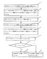
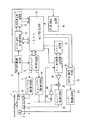
図1は本発明の記録制御方法を説明するためのフローチャート、図2は本発明に係る光ディスク記録再生装置の一実施例を示す回路図、図3、図4及び図5は本発明の動作を説明するための信号波形図である。 FIG. 1 is a flowchart for explaining a recording control method of the present invention, FIG. 2 is a circuit diagram showing an embodiment of an optical disk recording / reproducing apparatus according to the present invention, and FIGS. 3, 4 and 5 show operations of the present invention. It is a signal waveform diagram for explaining.
図2において、1はスピンドルモーター(図示せず)によって回転駆動されるディスクであり、内周側及び外周側には記録動作を行う場合にディスクの記録特性に合わせてレーザー出力を設定する試し書き領域が設けられている。また、斯かるディスク1には、位置情報データがプリグルーブと呼ばれる溝によって記録されており、この溝より得られるウォブル信号に基づいて信号の記録再生動作が行われるように構成されている。 In FIG. 2, reference numeral 1 denotes a disk that is rotationally driven by a spindle motor (not shown). On the inner and outer peripheral sides, a test writing that sets the laser output in accordance with the recording characteristics of the disk when performing a recording operation. An area is provided. In addition, the disc 1 is configured such that position information data is recorded in a groove called a pregroove, and a signal recording / reproducing operation is performed based on a wobble signal obtained from the groove.
2は前記ディスク1に照射されるレーザー光を放射させるレーザーダイオード3及び該レーザーダイオード3から照射されるレーザー光のレベルをモニターするモニター用ダイオード(図示せず)が組み込まれているとともにディスク1の信号面より反射されるレーザー光を受ける光検出器4が組み込まれている光学式ピックアップであり、ピックアップ送り用モーター(図示せず)によってディスクの径方向に移動せしめられるように構成されている。
また、前記光学式ピックアップ2には、対物レンズ(図示せず)をディスク1の信号面に対して垂直方向へ変位させるフォーカシングコイル5、対物レンズをディスク1の径方向へ変位させるトラッキングコイル6及び対物レンズのディスク1の信号面に対する角度を調整するチルト調整用コイル7が組み込まれている。
The
8は前記光学式ピックアップ2に組み込まれている光検出器4から得られる信号が入力されるとともに該信号を増幅するRF信号増幅回路であり、RF信号を波形整形するとともに2値化した信号を出力するように構成されている。9は前記光検出器4より得られる信号から生成されるフォーカスエラー信号及びトラッキングエラー信号に基づいてレーザー光をディスク1の信号面に合焦させるフォーカシング制御動作及び該レーザー光を信号トラックに追従させるトラッキング制御動作を行うピックアップ制御回路であり、フォーカスエラー信号に基づくフォーカシング制御信号及びトラッキングエラー信号に基づくトラッキング制御信号を出力するように構成されている。
Reference numeral 8 denotes an RF signal amplifier circuit that receives a signal obtained from the photodetector 4 incorporated in the
10は前記ピックアップ制御回路9より出力されるフォーカシング制御信号が入力されるフォーカシングコイル駆動回路であり、前記光学式ピックアップ2に組み込まれているフォーカシングコイル5に駆動信号を供給するように構成されている。11は前記ピックアップ制御回路9より出力されるトラッキング制御信号が入力されるトラッキングコイル駆動回路であり、前記光学式ピックアップ2に組み込まれているトラッキングコイル6に駆動信号を供給するように構成されている。
12は前記RF信号増幅回路8から出力される2値化信号が入力されるとともに該信号の処理動作を行うデジタル信号処理回路であり、各種信号の復調処理動作を行うように構成されている。13は前記デジタル信号処理回路12によって復調された信号が入力される信号再生用回路、14は光ディスク記録再生装置の各動作を制御するシステム制御回路である。
Reference numeral 12 denotes a digital signal processing circuit that receives the binarized signal output from the RF signal amplifying circuit 8 and performs a processing operation on the signal, and is configured to perform a demodulation processing operation on various signals.
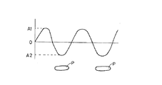
15は前記RF信号増幅回路8から出力される信号からβ値を検出するとともに検出されたβ値を前記システム制御回路14に出力するβ値検出回路である。ここで斯かるβ値について説明する。図3はディスク1に記録されている信号を再生した信号の波形図であ
り、A1及びA2は高周波信号のプラス側のピークレベル及びマイナス側のピークレベルである。
Reference numeral 15 denotes a β value detection circuit that detects the β value from the signal output from the RF signal amplifier circuit 8 and outputs the detected β value to the
斯かる条件において、β値は、β=(A1+A2)/(A1−A2)と表され、このβ値がディスクの記録特性に基づいて設定された値になるとき、記録動作に適したレーザー出力値となる。一方、ディスク1の信号面に対する対物レンズの傾き、即ちチルトの角度とβ値との関係は、チルト調整が良好になるほどβ値が大きくなるという特性がある。 Under such conditions, the β value is expressed as β = (A1 + A2) / (A1−A2). When this β value becomes a value set based on the recording characteristics of the disc, the laser output suitable for the recording operation is obtained. Value. On the other hand, the relationship between the tilt of the objective lens with respect to the signal surface of the disk 1, that is, the tilt angle and the β value has a characteristic that the β value increases as the tilt adjustment becomes better.
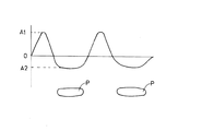
斯かる特性について説明する。図3において、Pはディスク1にレーザー光を照射させることによって形成されるピットを示すものであり、再生信号の波形とピットとの関係を示すものである。図4は図3に示した状態よりチルトの調整が良好になった状態を示すものであり、同一のレーザー出力にて記録した場合に形成されるピットPの形状はレーザー光が効率良くディスク1の信号面に照射されるので、大きく形成されることになる。図4に示す再生波形図より明らかなようにピットPの形状が大きくなると、高周波信号のプラス側のピークレベルが高くなるとともにマイナス側のピークレベルが低くなる。このようにチルト角度調整が良好になると、A1及びA2の値が変化する結果、β値が大きくなることが分かる。 Such characteristics will be described. In FIG. 3, P indicates a pit formed by irradiating the disk 1 with laser light, and indicates the relationship between the waveform of the reproduction signal and the pit. FIG. 4 shows a state in which the tilt adjustment is better than the state shown in FIG. 3, and the shape of the pit P formed when recording is performed with the same laser output, the laser beam is more efficient. Therefore, it is formed large. As apparent from the reproduction waveform diagram shown in FIG. 4, when the shape of the pit P is increased, the positive peak level of the high-frequency signal is increased and the negative peak level is decreased. As described above, when the tilt angle adjustment is good, the values of A1 and A2 change, and as a result, the β value increases.
16は前記システム制御回路14によって動作が制御されるとともに前記フォーカシングコイル駆動回路10より出力される駆動信号を利用してチルト制御動作を行うチルト制御回路、17は前記システム制御回路14によって動作が制御されるメモリー回路であり、前記チルト制御回路16から得られるデータ、即ちチルト角度のデータが記憶されるように構成されている。
18は前記チルト制御回路16より出力される信号を増幅する増幅回路、19は前記フォーカシングコイル駆動回路10より出力される駆動信号の中から直流信号をカットするコンデンサ、20は前記コンデンサ19を通過する交流信号が入力されるとともに該信号を増幅する増幅回路である。21は前記増幅回路18にて増幅された直流信号と前記増幅回路20にて増幅された交流信号とを加算する加算回路である。22は前記加算回路21にて加算された信号が入力されるチルトコイル駆動回路であり、前記光学式ピックアップ2に組み込まれているチルト調整用コイル7にチルト調整用の駆動信号を供給するように構成されている。
23は前記光学式ピックアップ2に組み込まれているレーザーダイオード3に駆動信号を供給するレーザー駆動回路、24は前記システム制御回路14を通して入力される記録信号をディスク1に記録するための信号にエンコードして前記レーザー駆動回路23に供給する信号記録用回路であり、チルト角度の検出動作時にはオフセット調整用信号を出力するように構成されている。
また、ディスク1はスピンドルモーターによって線速度一定になるように回転駆動制御されるが、ディスク1の内周側では、規定の線速度に対して例えば4倍の線速度一定にて回転駆動され、外周側に移動するに従って8倍の線速度一定、更に12倍の線速度一定の状態にて回転駆動されるように構成されている。そして、記録速度が変更される毎にレーザー出力レベルやデジタル信号処理回路12等の信号処理速度が記録速度に対応して変更されるように構成されている。 Further, the disk 1 is rotationally driven and controlled so that the linear velocity is constant by a spindle motor. On the inner peripheral side of the disk 1, the disk 1 is rotationally driven at a constant linear velocity, for example, four times the specified linear velocity, As it moves to the outer peripheral side, it is configured to be driven to rotate at a constant linear velocity of 8 times and further at a constant linear velocity of 12 times. Each time the recording speed is changed, the laser output level and the signal processing speed of the digital signal processing circuit 12 and the like are changed corresponding to the recording speed.
以上に説明したように本発明に係る光ディスク記録再生装置は構成されているが、次に動作について説明する。通常の記録動作や再生動作が行われている状態では、光学式ピックアップ2に組み込まれている光検出器4より得られる信号からフォーカスエラー信号やトラッキングエラー信号を生成し、そのエラー信号に基づいてフォーカシング制御動作及
びトラッキング制御動作を行うための制御動作がピックアップ制御回路9によって行われる。
As described above, the optical disk recording / reproducing apparatus according to the present invention is configured. Next, the operation will be described. In a state in which a normal recording operation and reproduction operation are performed, a focus error signal and a tracking error signal are generated from a signal obtained from the photodetector 4 incorporated in the
前記ピックアップ制御回路9による各動作を行うための制御動作が行われると、フォーカシングコイル駆動回路10及びトラッキングコイル駆動回路11に該ピックアップ制御回路9から制御信号が出力される。その結果、前記フォーカシングコイル駆動回路10及びトラッキングコイル駆動回路11よりフォーカシングコイル5及びトラッキングコイル6に対して駆動信号が供給される。斯かる動作が行われる結果、光学式ピックアップ2より照射されるレーザー光をディスク1上の信号面に合焦させるフォーカシング制御動作及び信号トラックに追従させるトラッキング制御動作を行うことが出来る。
When a control operation for performing each operation by the pickup control circuit 9 is performed, a control signal is output from the pickup control circuit 9 to the focusing
以上に説明したようにピックアップ制御回路9によるフォーカシング制御動作及びトラッキング制御動作は行われるが、次にチルト制御動作について説明する。チルト制御動作を行うためには、まずディスク1の信号面と光学式ピックアップ2の対物レンズとの角度のズレを補正するために使用されるオフセット値の設定動作が行われる。斯かるオフセット値を設定するための動作は、システム制御回路14からチルト制御回路16に対してオフセット値を設定するための信号を出力させることによって行われる。
As described above, the focusing control operation and the tracking control operation by the pickup control circuit 9 are performed. Next, the tilt control operation will be described. In order to perform the tilt control operation, first, an operation for setting an offset value used for correcting a shift in the angle between the signal surface of the disk 1 and the objective lens of the
斯かる動作は、通常のチルト制御動作を行わない状態において、チルト制御回路16から出力される制御信号によってチルトコイル駆動回路22からチルト調整用コイル7に対してチルト角度を1段ずつ段階的に変更させるための信号を出力させることによって行われる。
In such an operation, in a state where the normal tilt control operation is not performed, the tilt angle from the tilt
斯かる制御信号がチルト制御回路16より出力されると、前記チルトコイル駆動回路22からチルト調整用コイル7に対して、対物レンズの傾きを一方の方向に1段階変更させるための駆動信号が供給される。その結果、前記チルト調整用コイル7の駆動動作によって対物レンズがチルト調整を行う方向に1段階傾けられる。
When such a control signal is output from the
オフセット検出動作時には、前記チルト制御回路16から出力される制御信号に基づいて対物レンズの傾きが1段階ずつ変更する動作が行われるが、斯かる動作は、ディスク1の内周側及び外周側に設けられている試し書き領域にオフセット調整用信号を記録しながら行われる。即ち、信号記録用回路24よりレーザー駆動回路23に対してオフセット調整用信号を出力させ、その信号をレーザーダイオード3より出力されるレーザー光によってディスク1の試し書き領域に記録する動作が行われる。斯かる記録動作が行われているとき、その記録位置とチルト制御回路16から出力される信号のレベルとの関係がメモリー回路17に記憶されるように構成されている。
During the offset detection operation, an operation of changing the tilt of the objective lens one step at a time based on the control signal output from the
チルト制御回路16より出力される信号に基づく対物レンズの角度変更動作が終了すると、ディスク1に記録されたオフセット調整用信号の再生動作が行われる。斯かる信号の再生動作は、オフセット調整用信号の記録動作を開始した位置に光学式ピックアップ2を移動させるとともにチルト調整用コイル7に駆動信号を供給していない状態、即ち対物レンズを中立の位置にした状態にて行われる。
When the operation of changing the angle of the objective lens based on the signal output from the
対物レンズのディスク1に対する角度、即ちチルト角度を変更させながら記録されたオフセット調整用信号の再生動作を行うと、ディスク1から反射して得られるRF信号のレベルが変化することになる。ディスク1に設けられている試し書き領域に記録されているオフセット調整用信号は、RF信号増幅回路8によって増幅された後β値検出回路15に入力される。 When the reproduction operation of the offset adjustment signal recorded while changing the angle of the objective lens with respect to the disk 1, that is, the tilt angle, the level of the RF signal reflected from the disk 1 changes. The offset adjustment signal recorded in the test writing area provided on the disk 1 is amplified by the RF signal amplification circuit 8 and then input to the β value detection circuit 15.
ディスク1の信号面に対する対物レンズの傾きが正しい方向に調整されるに従ってRF
信号から得られるA1値は大きくなり、A2値は小さくなる。それ故、チルト角度を段階的に変更しながら記録された信号を再生するとβ値が最大になった後に小さくなる。
RF as the tilt of the objective lens relative to the signal surface of the disc 1 is adjusted in the correct direction.
The A1 value obtained from the signal increases and the A2 value decreases. Therefore, when the recorded signal is reproduced while the tilt angle is changed stepwise, the β value becomes smaller after the maximum value.
このようにチルト調整用コイル7の駆動動作によって対物レンズの角度がチルト調整を行う方向ら段階的に変更されながらオフセット調整用信号を記録すると、その再生信号であるRF信号から得られるβ値が変化するため、そのβ値が最も大きくなるオフセット調整用信号が記録されている位置における駆動電圧がチルト調整用コイル7に供給されたときにチルト制御回路16より出力された制御信号の値をオフセット値としてメモリー回路17に記憶させる動作が行われる。
As described above, when the offset adjustment signal is recorded while the angle of the objective lens is changed stepwise from the direction in which the tilt adjustment is performed by the drive operation of the
前述したオフセット値を求める動作は、ディスク1の内周側に設けられている試し書き領域にて行われるが、斯かる動作が終了すると次に光学式ピックアップ2をディスク1の外周側に設けられている試し書き領域に移動させることによって外周側におけるオフセット値の設定動作が行われる。斯かる動作は、前述した動作と同様に行うことが出来るのでその説明は省略する。
The above-described operation for obtaining the offset value is performed in a test writing area provided on the inner circumference side of the disc 1. When such operation is completed, the
以上に説明したようにディスク1の内周位置及び外周位置におけるオフセット値の設定動作は行われるが、次にチルト調整動作について説明する。 As described above, the offset value setting operation at the inner and outer peripheral positions of the disk 1 is performed. Next, the tilt adjustment operation will be described.
光ディスク記録再生装置が記録状態にあるとき、光学式ピックアップ2とディスク1との関係がチルト調整を行う必要がある状態になると、チルト調整用コイル7に対物レンズの角度を変更するための駆動信号が供給されるが、この角度を変更させるためのチルト調整信号は、フォーカシングコイル5に供給される駆動信号を利用して行われる。
When the optical disk recording / reproducing apparatus is in a recording state, when the relationship between the
フォーカシングコイル駆動回路10からフォーカシングコイル5に供給される駆動信号は、直流電圧に交流信号が重畳された信号である。即ち、直流電圧は、対物レンズの位置を動作位置にする信号であり、交流信号はディスク1の速い動きに追従させて対物レンズを変位させるための信号である。そして、前述した交流信号は、ディスク1の信号面と光学式ピックアップ2の位置関係に応じて対物レンズを動作位置に変位させる信号であり、この駆動信号のレベル変化を利用することによってチルト調整を行うことが出来る。
The drive signal supplied from the focusing
フォーカシングコイル駆動回路10からフォーカシングコイル5に対して出力される駆動信号の変化成分をチルト調整用信号として抽出し、この抽出された信号に前記メモリー回路16に記憶されているオフセット値から算出される記録位置に応じたオフセット値を加算した信号をチルト制御用の信号としてチルトコイル駆動回路22に供給する。記録位置に応じたオフセット値は、前記メモリー回路17に記憶されているオフセット値、即ち内周側のオフセット値と外周側のオフセット値の差とディスク1の内周側と外周側との距離に基づいて算出することが出来る。
A change component of the drive signal output from the focusing
斯かる動作が行われる結果、チルトコイル駆動回路22からチルト調整用コイル7に対してチルト調整用の駆動信号が供給されるので光学式ピックアップ2のディスク1に対する角度を最適な状態にするための動作、即ちチルト調整動作が行われることになる。
As a result of such an operation, a tilt adjustment drive signal is supplied from the tilt
以上に説明したように本実施例における各調整動作は行われるが、次に本発明の要旨である記録制御方法について図1に示すフローチャートを参照して説明する。 As described above, each adjustment operation in the present embodiment is performed. Next, a recording control method that is the gist of the present invention will be described with reference to the flowchart shown in FIG.
記録動作を行うためにディスク1を光ディスク記録再生装置に設けられているディスク装着部に装着させると、まず光学式ピックアップ2をディスク1の内周側に設けられている試し書き領域に移動させる(ステップA)。
When the disc 1 is mounted on the disc mounting portion provided in the optical disc recording / reproducing apparatus for performing the recording operation, first, the
光学式ピックアップ2がディスク1の内周側に設けられている試し書き領域に移動すると、チルト角度を段階的に変更しながらオフセット調整用信号を記録し、記録されたオフセット調整用信号の再生特性から最適なチルト角度T1を求める(ステップB)。斯かるチルト角度T1は、前述したオフセット値を求める動作と同様に行うことが出来る。即ち、オフセット値とそのオフセット値に対応した対物レンズの角度とをテーブルデータとしてメモリー回路17に記憶させておき、前述したオフセット値の設定動作によって得られる最適オフセット値に対応した角度を内周側におけるチルト角度T1として設定記憶させる(ステップC)。
When the
内周側に設けられている試し書き領域にて求められたチルト角度T1のメモリー回路17への記憶動作が終了すると、光学式ピックアップ2をディスク1の外周側にある試し書き領域に移動させる(ステップD)。斯かる試し書き領域への移動動作は、プリグルーブから得られるアドレスデータを検出することによって行うことが出来るが、斯かる動作は周知のサーチ動作によって行うことが出来るのでその説明は省略する。
When the storage operation of the tilt angle T1 obtained in the test writing area provided on the inner peripheral side in the
光学式ピックアップ2がディスク1の外周側に設けられている試し書き領域に移動すると、チルト角度を段階的に変更しながらオフセット調整用信号を記録し、記録されたオフセット調整用信号の再生特性から最適なチルト角度T2を求める(ステップE)。斯かるチルト角度T2は、前述したチルト角度T1と同様の動作によって求めることが出来る。
When the
前述した動作によってチルト角度T1とT2が求められると、次にT1とT2との差を求める(ステップF)。斯かる動作によってチルト角度T1とT2との差、即ち絶対値|T1−T2|が求められたら、その大きさが設定値T0より大きいか否かの判定を行う(ステップG)。斯かる設定値T0は、ディスク1の反りの影響により外周側における記録線速度の変更を行うことが出来るか否かを判定する基準となる角度である。即ち、この設定値T0より絶対値|T1−T2|が大きいということは、ディスク1の反りが大きいと判定することが出来る。 When the tilt angles T1 and T2 are obtained by the above-described operation, the difference between T1 and T2 is then obtained (step F). When the difference between the tilt angles T1 and T2, that is, the absolute value | T1-T2 | is obtained by such an operation, it is determined whether or not the magnitude is larger than the set value T0 (step G). The set value T0 is an angle serving as a reference for determining whether or not the recording linear velocity on the outer peripheral side can be changed due to the influence of the warp of the disk 1. That is, if the absolute value | T1-T2 | is larger than the set value T0, it can be determined that the warp of the disk 1 is large.
ステップGにて絶対値|T1−T2|がT0より小さいと判定された場合には、ディスク1の反りが少ないので記録速度の高速側への変更を可能と判定する(ステップH)。反対に、ステップGにて絶対値|T1−T2|がT0より大きいと判定された場合には、ディスク1の反りが大きいので記録速度の高速側への変更を不可能と判定する(ステップI)。 If it is determined in step G that the absolute value | T1-T2 | is smaller than T0, it is determined that the recording speed can be changed to the high speed side because the warp of the disk 1 is small (step H). Conversely, if it is determined in step G that the absolute value | T1-T2 | is greater than T0, it is determined that the recording speed cannot be changed to the high speed side because the warpage of the disk 1 is large (step I). ).
斯かる判定動作を行うことにより記録位置が記録速度の変更動作を行うことが出来る位置に移動した場合に記録速度の変更動作を行うか否かを記録動作を開始する前に設定することが出来る。従って、記録動作を正常に行うことが出来ない速度への変更動作が行われないので、ディスク1の内周側から外周側まで記録動作を正常に行うことが出来る。 By performing such a determination operation, whether or not the recording speed changing operation is performed when the recording position is moved to a position where the recording speed changing operation can be performed can be set before starting the recording operation. . Accordingly, since the speed changing operation at which the recording operation cannot be normally performed is not performed, the recording operation can be normally performed from the inner circumference side to the outer circumference side of the disk 1.
前述したように内周側及び外周側に設けられている試し書き領域にて光学式ピックアップ2のチルト角度を最適な状態になるように設定することが出来るので、斯かるチルト調整動作を行った後に記録動作を行うために適したレーザー出力の設定動作を行えば記録動作に適したレーザー出力の設定動作を正確、且つ効率良く行うことが出来る。斯かるレーザー出力の設定動作は、レーザー出力を変更しながらテスト信号の記録動作を行い、その記録されたテスト信号の記録特性を認識することによって行うことができるが、斯かる記録特性の認識動作は、前述したβ値検出回路15を利用して行うことが出来る。
As described above, the tilt angle of the
内周側及び外周側に設けられている試し書き領域において、レーザー出力を変更しながらテスト信号を記録し、その記録されたテスト信号を再生し、前記β値検出回路15にて検出されるβ値がディスク1の特性に適した値になるテスト信号を記録したレーザー出力をディスクの記録動作に適したレーザー出力として設定することになる。 In the test writing areas provided on the inner and outer peripheral sides, a test signal is recorded while changing the laser output, the recorded test signal is reproduced, and β detected by the β value detecting circuit 15 The laser output recording the test signal whose value is suitable for the characteristics of the disc 1 is set as the laser output suitable for the recording operation of the disc.
前述したように本実施例の各動作は行われるが、オフセット調整用信号の再生し、その再生された信号のβ値によってチルト角度に対応した記録特性の変化を検出するようにしたが、RF信号のレベルを利用することも出来る。即ち、ディスク1の信号面に対する対物レンズの角度が良好になるほどディスクに記録されるピットの形状が大きくなり、その記録された信号のRF信号のレベルが大きくなるという特性がある。 As described above, each operation of this embodiment is performed, but the offset adjustment signal is reproduced, and the change in the recording characteristic corresponding to the tilt angle is detected by the β value of the reproduced signal. The signal level can also be used. That is, the better the angle of the objective lens with respect to the signal surface of the disc 1, the larger the shape of the pits recorded on the disc, and the higher the RF signal level of the recorded signal.
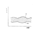
図5はRF信号増幅回路8から得られるRF信号の波形を示すものであり、実線Aはピークレベル、実線Bはボトムレベルを示している。従って、β値検出回路15ではなくRF信号のピークレベル及びボトムレベルを検出する各検出回路を設け、その各レベルの変化を検出することによってチルト角度に対応した記録特性の変化を検出することが出来ることになる。 FIG. 5 shows the waveform of the RF signal obtained from the RF signal amplifying circuit 8. The solid line A shows the peak level and the solid line B shows the bottom level. Therefore, each detection circuit for detecting the peak level and the bottom level of the RF signal is provided instead of the β value detection circuit 15, and the change in the recording characteristic corresponding to the tilt angle can be detected by detecting the change in each level. It will be possible.
そして、対物レンズとディスク1の信号面との関係が良好になるに従ってピークレベルが大きくなり、反対にボトムレベルは小さくなるという特性があるので、ピークレベルが最大になる点又はボトムレベルが最小となる点に対応したチルト角度が最適なチルト角度であると認識することが出来る。 Since the peak level increases as the relationship between the objective lens and the signal surface of the disk 1 becomes better, and the bottom level decreases, the peak level is maximized or the bottom level is minimized. It can be recognized that the tilt angle corresponding to this point is the optimum tilt angle.
1 ディスク
2 光学式ピックアップ
3 レーザーダイオード
4 光検出器
5 フォーカシングコイル
7 チルト調整用コイル
8 RF信号増幅回路
9 ピックアップ制御回路
10 フォーカシングコイル駆動回路
12 デジタル信号処理回路
14 システム制御回路
15 β値検出回路
16 チルト制御回路
17 メモリー回路
22 チルトコイル駆動回路
23 レーザー駆動回路
24 信号記録用回路
1 disc
2 Optical pickup
3 Laser diode
4 photodetectors
5 Focusing coil
7 Tilt adjustment coil
8 RF signal amplifier circuit
DESCRIPTION OF SYMBOLS 9
Claims (6)
Priority Applications (1)
| Application Number | Priority Date | Filing Date | Title |
|---|---|---|---|
| JP2004051476A JP2005243136A (en) | 2004-02-26 | 2004-02-26 | Recording control method of optical disk recording or reproducing apparatus |
Applications Claiming Priority (1)
| Application Number | Priority Date | Filing Date | Title |
|---|---|---|---|
| JP2004051476A JP2005243136A (en) | 2004-02-26 | 2004-02-26 | Recording control method of optical disk recording or reproducing apparatus |
Publications (1)
| Publication Number | Publication Date |
|---|---|
| JP2005243136A true JP2005243136A (en) | 2005-09-08 |
Family
ID=35024709
Family Applications (1)
| Application Number | Title | Priority Date | Filing Date |
|---|---|---|---|
| JP2004051476A Pending JP2005243136A (en) | 2004-02-26 | 2004-02-26 | Recording control method of optical disk recording or reproducing apparatus |
Country Status (1)
| Country | Link |
|---|---|
| JP (1) | JP2005243136A (en) |
-
2004
- 2004-02-26 JP JP2004051476A patent/JP2005243136A/en active Pending
Similar Documents
| Publication | Publication Date | Title |
|---|---|---|
| JP2005243137A (en) | Recording control method of optical disk recording or reproducing apparatus | |
| JP2005243136A (en) | Recording control method of optical disk recording or reproducing apparatus | |
| JP2004095044A (en) | Tilt control method for optical disk recording/reproducing device | |
| JP4353876B2 (en) | Recording control method for optical disc recording / reproducing apparatus | |
| JP2006185482A (en) | Optical pickup tilt correction control apparatus and tilt correction method | |
| JP4302044B2 (en) | Recording control method for optical disc recording / reproducing apparatus | |
| JP2006085842A (en) | Recording control method for optical disk recording and playback apparatus | |
| JP2005174387A (en) | Tilt control method for optical disk recording/reproducing device | |
| JP2005158206A (en) | Tilt control method of optical disk recording or reproducing apparatus | |
| JP5076846B2 (en) | Optical disk device | |
| JP2005166191A (en) | Tilt control method for optical disk recording and reproducing apparatus | |
| JP2004199779A (en) | Tilt control method for optical disk recording and reproducing device | |
| JP2006107632A (en) | Focus control method for optical disk recording/reproducing device | |
| JP2006147047A (en) | Recording control method for optical disk recording-and-reproducing device | |
| JP2005158138A (en) | Tilt control method of optical disk recording or reproducing apparatus | |
| JP2006099861A (en) | Reproduction control method for optical disk device | |
| JP2004095129A (en) | Tilt control method for optical disk recording/reproducing device | |
| JP2006155778A (en) | Recording control method for optical disk recording/reproducing device | |
| JP2005166192A (en) | Tilt control method for optical disk recording and reproducing apparatus | |
| JP2005158207A (en) | Tilt control method of optical disk recording or reproducing apparatus | |
| JP2006164412A (en) | Method for focus control of optical disk recording and reproducing apparatus | |
| JP2004110990A (en) | Method for controlling tilt of optical disk recorder/player | |
| JP2005158173A (en) | Tilt control method of optical disk recording or reproducing apparatus | |
| JP2006164411A (en) | Method for focus control of optical disk recording and reproducing apparatus | |
| JP2005158137A (en) | Tilt control method of optical disk recording or reproducing apparatus |
Legal Events
| Date | Code | Title | Description |
|---|---|---|---|
| RD01 | Notification of change of attorney |
Free format text: JAPANESE INTERMEDIATE CODE: A7421 Effective date: 20051226 |