JP2005236917A - Ip telephone gateway device and ip telephone calling number notifying method - Google Patents
Ip telephone gateway device and ip telephone calling number notifying method Download PDFInfo
- Publication number
- JP2005236917A JP2005236917A JP2004046906A JP2004046906A JP2005236917A JP 2005236917 A JP2005236917 A JP 2005236917A JP 2004046906 A JP2004046906 A JP 2004046906A JP 2004046906 A JP2004046906 A JP 2004046906A JP 2005236917 A JP2005236917 A JP 2005236917A
- Authority
- JP
- Japan
- Prior art keywords
- telephone
- calling
- calling number
- number notification
- network
- Prior art date
- Legal status (The legal status is an assumption and is not a legal conclusion. Google has not performed a legal analysis and makes no representation as to the accuracy of the status listed.)
- Pending
Links
Images


Abstract
Description
本発明は、IP電話機能を持たない電話機をIP網経由で通信(通話を含む)可能にするIP電話ゲートウェイ装置及びIP電話発番号通知方法に関する。 The present invention relates to an IP telephone gateway apparatus and an IP telephone calling number notification method that enable a telephone having no IP telephone function to communicate (including a telephone call) via an IP network.
IP電話機能を持たない既存の電話機から通信事業者の提供するIP電話サービスを利用する場合、IP電話ゲートウェイ装置を用いることができる。1台のIP電話ゲートウェイ装置に対して複数台の電話機を接続可能に構成している。例えば、1台のIP電話ゲートウェイ装置に対して複数の内線電話機(アナログ電話機等)を接続して、各内線電話機からIP電話ゲートウェイ装置経由でIP網に接続して外線通話することも可能である。 When using an IP telephone service provided by a communication carrier from an existing telephone that does not have an IP telephone function, an IP telephone gateway device can be used. A plurality of telephones can be connected to one IP telephone gateway device. For example, it is also possible to connect a plurality of extension telephones (analog telephones, etc.) to one IP telephone gateway apparatus, and connect to the IP network via the IP telephone gateway apparatus from each extension telephone to make an external line call. .
ところで、最近は通信事業者が発信者の契約電話番号を着信者に対して通知する発信者番号通知サービスを行っている。複数の内線電話機から特定のIP電話ゲートウェイ装置経由でIP網に接続するシステム構成において発番号通知を行おうとした場合、いずれの内線電話を使用してもIP電話ゲートウェイ装置の契約者回線番号が着信側に通知されることとなる。 By the way, recently, a telecommunications carrier has performed a caller number notification service for notifying a caller of a contract telephone number of a caller. In a system configuration where multiple extension telephones are connected to the IP network via a specific IP telephone gateway device, the subscriber line number of the IP telephone gateway device is received regardless of which extension telephone is used. Will be notified.
なお、構内交換機に収容された内線電話機から局線にダイヤル発信する場合に着信側に通知される発信者番号の通知を内線電話機が接続される局線に拘わらず、任意の発信者番号を選択して通知できる構内交換機システムがある(例えば特許文献1参照)。
しかしながら、1台のIP電話ゲートウェイ装置に対して契約者回線番号の他に複数の追加番号を取得できる場合、そこに接続される電話機毎に契約者回線番号又は追加番号のいずれかを選択して発番号通知に使用したくても、契約者回線番号しか使用できていなかった。 However, if a plurality of additional numbers in addition to the subscriber line number can be acquired for one IP telephone gateway device, select either the subscriber line number or the additional number for each telephone connected to the IP telephone gateway device. Even if I wanted to use it for calling number notification, I could only use the subscriber line number.
本発明は、以上のような実情に鑑みてなされたもので、発信者番号選択機能を持った構内交換機システムを備えることなく、電話機毎に契約者回線番号又は追加番号のいずれかを選択して発番号通知に使用可能なIP電話ゲートウェイ装置及びIP電話発番号通知方法を提供することを目的とする。 The present invention has been made in view of the above circumstances, and selects either a subscriber line number or an additional number for each telephone without providing a private branch exchange system having a caller number selection function. It is an object of the present invention to provide an IP telephone gateway device and an IP telephone calling number notification method that can be used for calling number notification.
本発明は、電話機の送出した発信要求を検出し、契約者回線番号及び追加番号の中から発番号通知に使用する番号を電話機毎に設定した発番号通知テーブルから、今回発信要求してきた電話機の発番号通知用として登録した番号を取得し、この取得した番号を含んだトランザクション開始リクエストを生成し、IP網上に配置されIP電話におけるネットワークホストの役目を行うサーバーに対して前記トランザクション開始リクエストを送出するものである。 The present invention detects a call request sent from a telephone, and from the calling number notification table in which the number used for calling number notification is set for each telephone from the subscriber line number and the additional number, Acquires the number registered for calling number notification, generates a transaction start request including the acquired number, and sends the transaction start request to a server arranged on the IP network and acting as a network host in the IP telephone. To be sent.
本発明によれば、発信者番号選択機能を持った構内交換機システムを備えることなく、電話機毎に契約者回線番号又は追加番号のいずれかを選択して発番号通知に使用可能なIP電話ゲートウェイ装置及びIP電話発番号通知方法を提供できる。 According to the present invention, an IP telephone gateway device that can be used for calling number notification by selecting either a subscriber line number or an additional number for each telephone without providing a private branch exchange system having a caller number selection function. And an IP telephone calling number notification method.
本発明の第1の態様は、複数の電話機を回線接続可能な回線インターフェース手段と、IP電話におけるネットワークホストの役目を行うサーバーが配置されたIP網との間の通信を制御するネットワーク制御手段と、前記サーバーと連携したトランザクション制御にて前記電話機によるIP網経由の通話を実現するVoIP制御手段と、契約者回線番号及び追加番号の中から発番号通知に使用する番号を前記電話機毎に設定した発番号通知テーブルとを具備し、前記VoIP制御手段は、発信要求してきた電話機について発番号通知用として登録した番号を前記発番号通知テーブルから取得し、この取得した番号を含んだトランザクション開始リクエストを生成して前記サーバーへ送出するIP電話ゲートウェイ装置である。 According to a first aspect of the present invention, there is provided a line interface means capable of connecting a plurality of telephone lines, and a network control means for controlling communication between an IP network in which a server serving as a network host in an IP telephone is arranged. VoIP control means for realizing a telephone call via the IP network by transaction control in cooperation with the server, and a number used for calling party number notification among the subscriber line number and additional number are set for each telephone. A calling number notification table, wherein the VoIP control unit obtains a number registered for calling number notification from the calling number notification table for the telephone that has requested transmission, and sends a transaction start request including the acquired number. An IP telephone gateway device that generates and sends to the server.
このように構成されたIP電話ゲートウェイ装置によれば、契約者回線番号及び追加番号の中から発番号通知に使用する番号を前記電話機毎に設定した発番号通知テーブルを具備し、発信要求してきた電話機の発番号通知用の番号を発番号通知テーブルから取り出してサーバーへ送信するので、発信者番号選択機能を持った構内交換機システムを備えることなく、電話機毎に契約者回線番号又は追加番号のいずれかを発番号通知に使用できる。 According to the IP telephone gateway apparatus configured as described above, the calling telephone number notification table in which the number used for the calling party number notification is set for each telephone from the subscriber line number and the additional number is provided, and the outgoing call is requested. Since the number for calling number notification of the telephone is extracted from the calling number notification table and transmitted to the server, either a subscriber line number or an additional number is set for each telephone without providing a private branch exchange system having a caller number selection function. Can be used for calling number notification.
なお、VoIP制御手段は、RFC2543,3261に定められたSIP(Session Initiation Protocol)に従って動作する場合は、前記発番号通知テーブルから取得した番号をFromヘッダに設定したINVITEを前記トランザクション開始リクエストとして生成することが望ましい。 When the VoIP control unit operates in accordance with SIP (Session Initiation Protocol) defined in RFC2543 and 3261, it generates INVITE in which the number acquired from the calling number notification table is set in the From header as the transaction start request. It is desirable.
本発明の第2の態様は、電話機の送出した発信要求を検出し、契約者回線番号及び追加番号の中から発番号通知に使用する番号を電話機毎に設定した発番号通知テーブルから、今回発信要求してきた電話機の発番号通知用として登録した番号を取得し、この取得した番号を含んだトランザクション開始リクエストを生成し、IP網上に配置されIP電話におけるネットワークホストの役目を行うサーバーに対して前記トランザクション開始リクエストを送出するIP電話発番号通知方法である。 According to a second aspect of the present invention, a call request sent from a telephone is detected, and this call is sent from a calling number notification table in which a number used for calling number notification is set for each telephone from the subscriber line number and the additional number. Acquires the number registered for the caller ID notification of the requesting telephone, generates a transaction start request including the acquired number, and is placed on the IP network to the server acting as the network host in the IP telephone An IP telephone calling number notification method for transmitting the transaction start request.
以下、本発明の一実施の形態であるIP電話ゲートウェイ装置について図面を参照して具体的に説明する。 Hereinafter, an IP telephone gateway apparatus according to an embodiment of the present invention will be specifically described with reference to the drawings.
図1は、IP電話ゲートウェイ装置の運用構成を示す図である。IP電話ゲートウェイ装置100は、複数のアナログ通信機器(アナログ電話機、ファックス、主装置(PBX)、ビジネスホン)を接続する回線ポートを有しており、電話機(1)から電話機(n)を接続した状態を示している。また、IP電話ゲートウェイ装置100はIP網に接続されており、IP網上に配置したCA(コールエージェント;プロキシサーバーおよび登録サーバーを含む)サーバー11と連携して電話機(1)から電話機(n)によるIP網経由の通話を可能にしている。CAサーバー11とIP電話ゲートウェイ装置100との間ではRFC2543,3261に定められたSIP(Session Initiation Protocol)に基づいてリクエスト及びレスポンスを交換するものとする。IP網と電話網との間はゲートウェイ12によって繋がっている。
FIG. 1 is a diagram showing an operational configuration of an IP telephone gateway device. The IP
図2は、本実施の形態に係るIP電話ゲートウェイ装置の機能ブロック図である。電話制御部101は、IP電話ゲートウェイ装置に接続したアナログ通信機器(アナログ電話機、ファックス、主装置(PBX)、ビジネスホン)の電話制御を行う部分である。PSTN回線制御部102は、PSTNとの間で回線制御を行う部分である。本例では、IP電話ゲートウェイ装置100が1回線だけ直接PSTNに接続しているものとする。IP/PSTN切替え部103は、電話機がIP網に接続するのかPSTNに接続するのかを判断して、切り替える部分である。LAN側ネットワーク制御部104は、LANとのインターフェースをとる部分である。WAN側ネットワーク制御部105は、IP網側となるWANとのインターフェースをとる部分である。本例では、IP電話ゲートウェイ装置100をローカル側となるLANに接続可能にしている。また、IP電話ゲートウェイ装置100をADSL回線又は光ファイバ回線にてWAN側となるIP網に接続している。VoIP制御部106は、SIPに基づいたトランザクション制御並びに音声のパケット化等の音声データをインターネットに流すための処理を行っている部分である。サーバー部107は、DHCP等のプロトコルに基づいて動作し、例えばLAN側に接続している端末のアドレス管理等を行う部分である。IP/PPP処理部108は、LAN及びWAN(インターネット/イントラネット等)通信で必要なIP及びPPPに関するプロトコル処理を行う部分である。
FIG. 2 is a functional block diagram of the IP telephone gateway device according to the present embodiment. The
図3は、以上の機能構成を有するIP電話ゲートウェイ装置100のハードウエア構成図である。CPU/DSP110に対して内部バスを介してROM111,RAM112が接続され、さらに回線I/F回路113−1,113−2、NCU(DAA)114が接続されている。CPU/DSP110は、ROM111に格納しているプログラムに基づいて後述するSIPインターフェース制御を実行する。また、必要に応じてRAM112を作業用エリアとして使用する。回線I/F回路113−1、113−2は、アナログ通信機器(アナログ電話機、ファックス、主装置(PBX)、ビジネスホン)が接続されるポートをそれぞれ2回線備えており、全部で4回線接続可能に構成されている。なお、同時に接続可能な回線数は適宜設計変更可能である。NCU(DAA)114は、図2におけるPSTN回線制御部102のハードウエア部分である。図2におけるVoIP制御部106の音声パケット化に関する処理は、CPU/DSP110のDSP部分で一部ハードウエア化している。
FIG. 3 is a hardware configuration diagram of the IP
ここで、IP電話ゲートウェイ装置100は、契約者回線番号の他に追加番号1−nを通信事業者から取得しているものとする。本実施の形態では、IP電話ゲートウェイ装置100に接続する電話機毎にいずれかの電話番号を発番号通知用に使用できるように構成している。そのため、RAM112に発番号通知テーブルを記憶している。
Here, it is assumed that IP
図4は発番号通知テーブルの設定例を示す図である。電話機(1)には契約者回線番号(aa-bbbb-cccc)、電話機(2)には追加番号1(aa-dddd-eeee)、電話機(n−1)には追加番号n−1(aa-hhhh-iiii)、電話機(n)には追加番号n(aa-jjjj-kkkk)をそれぞれ発番号通知に使用する電話番号として設定している(図4上で○が付加されている番号が設定された番号である)。図4の登録例は一例であり、各電話機に対して発信者番号として使用したい番号を契約者回線番号、追加番号の中から任意に選択可能である。発番号通知テーブルの設定はユーザが予め行うものとする。 FIG. 4 is a diagram showing a setting example of the calling number notification table. Subscriber line number (aa-bbbb-cccc) for telephone (1), additional number 1 (aa-dddd-eeee) for telephone (2), additional number n-1 (aa) for telephone (n-1) -hhhh-iiii), and the telephone number (n) is set with the additional number n (aa-jjjj-kkkk) as the telephone number to be used for calling number notification (numbers with a circle in FIG. 4). Set number). The registration example of FIG. 4 is an example, and a number that is desired to be used as a caller number for each telephone can be arbitrarily selected from a subscriber line number and an additional number. The calling number notification table is set in advance by the user.
次に、以上のように構成したIP電話ゲートウェイ装置100の発信時及び着信時の動作について説明する。なお、本実施の形態において、VoIP制御部106がSIPに従った制御を行っている。
Next, operations at the time of outgoing call and incoming call of the IP
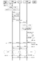
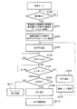
図5は、発信から通話までのシーケンスである。図6に当該シーケンスに対応した発信側のフロー図を示し、図7に当該シーケンスに対応した着信側のフロー図を示している。 FIG. 5 is a sequence from calling to calling. FIG. 6 shows a flowchart on the calling side corresponding to the sequence, and FIG. 7 shows a flowchart on the receiving side corresponding to the sequence.
図5に示すように、発番号通知テーブルに発番号通知用として「契約者回線番号」を設定した電話機1から発信する。電話機1をオフフックして相手先をダイヤルする。発信側のIP電話ゲートウェイ装置100は、電話機1からの発信要求を検出すると(S100)、発番号通知テーブルから発信者である電話機1の発番号通知用の番号を取得する(S101)。発番号通知テーブルから取得した番号を、トランザクション開始リクエストとなるINVITEのFromヘッダに設定する(S102)。図8にINVITEの記述例を示す。ここでは、契約者回線番号(aa-bbbb-cccc)が発番号通用に選択されているのでその番号を設定する。発信側のIP電話ゲートウェイ100は、CAサーバー11に対して上記INVITEを送出する(S103)。
As shown in FIG. 5, the call is sent from the telephone set 1 in which “contractor line number” is set for calling number notification in the calling number notification table. The telephone 1 is off-hooked and the other party is dialed. When the IP
CAサーバー11は、INVITEを検出すると、レスポンス(100Trying)を返す。さらに、発信側のIP電話ゲートウェイ装置に対して認証を要求する407Proxy Authentication Requiredにて認証ヘッダを返す。
When the
発信側のIP電話ゲートウェイ装置100は、100Tryingを検出し(S104)、レスポンスである407Proxy Authentication Requiredを検出すると(S105)、CAサーバー11に対してACKを返す(S106)。さらに、407Proxy Authentication Requiredで受信した暗号キーを元にアカント情報をデコードした認証ヘッダ付のINVITEに設定し(S107)、当該INVITEをCAサーバー11へ送出する(S103)。
The originating IP
CAサーバー11は、認証ヘッダの設定されたINVITEを検出すると、発信側のIP電話ゲートウェイ装置100に対しては100Tryingを返し、認証が正しければ、着信側のIP電話ゲートウェイ装置に対しては発信側から受信したINVITEを送出する。
When the
図7に示すように、着信側のIP電話ゲートウェイ装置は、該当電話機が使用可能であるか判断する(S200)。着信先の電話機が使用可能であれば、受信したINVITEのFromヘッダを確認し(S201)、着信先の電話機に対してFromヘッダに記述している発番号を通知する発信者番号通知処理を実行する(S202)。すなわち、着信先の電話機に対して発番号通知要求(CAR)を出力し、一次応答があれば発番号情報を通知する。 As shown in FIG. 7, the IP telephone gateway device on the called side determines whether or not the corresponding telephone can be used (S200). If the destination telephone is usable, the received INVITE From header is confirmed (S201), and a caller ID notification process for notifying the destination telephone of the calling number described in the From header is executed. (S202). That is, a calling number notification request (CAR) is output to the destination telephone, and if there is a primary response, the calling number information is notified.
着信側のIP電話ゲートウェイ装置は、着信側の電話機から受信完了応答を受信したら、当該着信側の電話機に対して着信要求(16Hz)を出して電話機を鳴動させる(S203)。このとき、着信側の電話機は、発番号(aa-bbbb-cccc)をディスプレイに表示させる。 When receiving the reception completion response from the incoming side telephone, the incoming side IP telephone gateway device issues an incoming call request (16 Hz) to the incoming side telephone and rings the telephone (S203). At this time, the telephone on the called side displays the calling number (aa-bbbb-cccc) on the display.
これにより、発信側のIP電話ゲートウェイ装置100が、発信者(電話機1)の発番号通知用の番号を、着信側の電話機に通知してディスプレイに表示できたことになる。
As a result, the IP
一方、着信側のIP電話ゲートウェイ装置は、発信側に対して180Ringingを送出する(S204)。また、オフフックを検出したら(S205)、着信先の電話機に対して鳴動停止を指示して(S206)、発信側に対して200OKを送出する(S207)。着信側のIP電話ゲートウェイ装置が送出した180Ringing及び200OKはCAサーバー11を経由して発信側のIP電話ゲートウェイ装置100へ渡される。
On the other hand, the IP telephone gateway device on the receiving side sends 180 Ringing to the calling side (S204). When an off-hook is detected (S205), the destination telephone is instructed to stop ringing (S206), and 200 OK is sent to the caller (S207). The 180 Ringing and 200 OK sent from the incoming IP telephone gateway device are delivered to the outgoing IP
図6に示すように、発信側のIP電話ゲートウェイ装置100は、180Ringingを受信した場合はステップS108へ移行して200OKの受信を待機し、200OKを受信したらCAサーバー11に対してACKを返す(S109)。ACK送出後はVoIP通話処理を開始する(S110)。なお、200OKを受信できないときはセッション処理を終了する(S111)。
As shown in FIG. 6, when receiving 180 Ringing, the originating IP
また、発信側のIP電話ゲートウェイ装置100がステップS109で送出したACKはCAサーバー11経由で着信側のIP電話ゲートウェイ装置へ伝えられる。図7に示すように、着信側のIP電話ゲートウェイ装置はACKを受信すると(S208)、VoIP通話処理を開始する(S209)。なお、ステップS200において着信先の電話機が使用中であった場合は発信側にその旨を伝える使用中処理を実行する(S210)。
Also, the ACK sent by the originating IP
どちらか一方がオンフックすることにより終話処理が行われる。図5の例では発信側がオンフックしている。オンフックを検知した発信側のIP電話ゲートウェイ装置100からBYEが送信されて着信側のIP電話ゲートウェイ装置が受信すると、着信者(電話機)に対してビジートーンを送出する。
When either one goes on-hook, the end-of-call process is performed. In the example of FIG. 5, the caller is on hook. When BYE is transmitted from the originating IP
以上の説明は発信者が電話機1の場合であったが、他の電話機から発信する場合も、発番号通知テーブルから当該電話機の発番号通知用の番号を取得して、着信先へ通知するので、電話機毎に任意の発番号を着信先の電話機へ通知することになる。 The above explanation is for the case where the caller is the telephone 1, but even when making a call from another telephone, the calling number notification number of the telephone is acquired from the calling number notification table and notified to the destination. An arbitrary calling number is notified to the destination telephone for each telephone.
このように本実施の形態によれば、構内交換機システムを備えなくても、IP電話ゲートウェイ装置100がテーブル情報にしたがって電話機毎に指定している発番号を認識して着信先へ通知することができる。これにより、IP電話ゲートウェイ装置に契約者回線番号の他に追加番号を取得している場合に、当該IP電話ゲートウェイ装置に接続される電話機毎に契約者回線番号の他に追加番号の中から任意の番号を発番号として設定することができる。
As described above, according to the present embodiment, even if the private branch exchange system is not provided, the IP
本発明は、発信者番号選択機能を持った構内交換機システムを備えることなく、電話機毎に契約者回線番号又は追加番号のいずれかを選択して発番号通知可能であり、IP電話ゲートウェイ装置及びIP電話発番号通知方法に適用可能である。 The present invention is capable of notifying a calling party number by selecting either a subscriber line number or an additional number for each telephone without providing a private branch exchange system having a caller number selection function. It can be applied to a telephone number notification method.
100 IP電話ゲートウェイ装置
101 電話制御部
102 PSTN回線制御部
103 IP/PSTN切替え部
104 LAN側ネットワーク制御部
105 WAN側ネットワーク制御部
106 VoIP制御部
107 サーバー部
110 CPU/DSP
111 ROM
112 RAM
113−1,113−2 回線I/F回路
DESCRIPTION OF
111 ROM
112 RAM
113-1, 113-2 Line I / F circuit
Claims (3)
Priority Applications (1)
| Application Number | Priority Date | Filing Date | Title |
|---|---|---|---|
| JP2004046906A JP2005236917A (en) | 2004-02-23 | 2004-02-23 | Ip telephone gateway device and ip telephone calling number notifying method |
Applications Claiming Priority (1)
| Application Number | Priority Date | Filing Date | Title |
|---|---|---|---|
| JP2004046906A JP2005236917A (en) | 2004-02-23 | 2004-02-23 | Ip telephone gateway device and ip telephone calling number notifying method |
Publications (2)
| Publication Number | Publication Date |
|---|---|
| JP2005236917A true JP2005236917A (en) | 2005-09-02 |
| JP2005236917A5 JP2005236917A5 (en) | 2007-04-05 |
Family
ID=35019382
Family Applications (1)
| Application Number | Title | Priority Date | Filing Date |
|---|---|---|---|
| JP2004046906A Pending JP2005236917A (en) | 2004-02-23 | 2004-02-23 | Ip telephone gateway device and ip telephone calling number notifying method |
Country Status (1)
| Country | Link |
|---|---|
| JP (1) | JP2005236917A (en) |
Cited By (3)
| Publication number | Priority date | Publication date | Assignee | Title |
|---|---|---|---|---|
| JP2007088637A (en) * | 2005-09-20 | 2007-04-05 | Ntt Communications Kk | Call control apparatus, voip communication system, voip apparatus, program, and call origination control method |
| JP2007221481A (en) * | 2006-02-16 | 2007-08-30 | Toshiba Corp | Telephone system |
| KR100894729B1 (en) | 2007-03-26 | 2009-04-24 | 큰사람컴퓨터 주식회사 | Conversation service method between USB internet phones and service server |
-
2004
- 2004-02-23 JP JP2004046906A patent/JP2005236917A/en active Pending
Cited By (5)
| Publication number | Priority date | Publication date | Assignee | Title |
|---|---|---|---|---|
| JP2007088637A (en) * | 2005-09-20 | 2007-04-05 | Ntt Communications Kk | Call control apparatus, voip communication system, voip apparatus, program, and call origination control method |
| JP4578368B2 (en) * | 2005-09-20 | 2010-11-10 | エヌ・ティ・ティ・コミュニケーションズ株式会社 | VoIP communication system and transmission control method |
| JP2007221481A (en) * | 2006-02-16 | 2007-08-30 | Toshiba Corp | Telephone system |
| US8000463B2 (en) | 2006-02-16 | 2011-08-16 | Kabushiki Kaisha Toshiba | Telephone system |
| KR100894729B1 (en) | 2007-03-26 | 2009-04-24 | 큰사람컴퓨터 주식회사 | Conversation service method between USB internet phones and service server |
Similar Documents
| Publication | Publication Date | Title |
|---|---|---|
| EP1725060A1 (en) | Wireless ip telephone unit | |
| JP5000215B2 (en) | Button telephone apparatus using SIP and its group representative incoming call and incoming call response method | |
| KR100876760B1 (en) | Method for converting call processing in internet protocol telephony exchange system | |
| JP4469209B2 (en) | IP telephone system, IP telephone apparatus and calling method | |
| US20100157995A1 (en) | Method for Setting Up a Telephone Connection, and Apparatuses | |
| US7016338B2 (en) | Methods, system and gateway for accessing features of equipment connected to a PSTN | |
| US20070147600A1 (en) | Multiple call origination | |
| JP2004229132A (en) | Communication equipment, its control method, and program | |
| JP4872762B2 (en) | Telephone equipment | |
| JP2005236917A (en) | Ip telephone gateway device and ip telephone calling number notifying method | |
| JP4111393B2 (en) | IP telephone system and IP telephone apparatus | |
| JP2005020676A (en) | Telephone communication method and apparatus | |
| JP2005244490A (en) | Ip telephone gateway device | |
| JP4135466B2 (en) | Communications system | |
| JP4383201B2 (en) | IP telephone gateway device | |
| JP2005269165A (en) | Ip phone | |
| JP2005051549A (en) | Gateway device, extension telephone switching system, and extension telephone switching method | |
| JP2005101817A (en) | Ip telephone system and ip telephone device | |
| JP5046007B2 (en) | IP telephone equipment | |
| JP4906823B2 (en) | Call control method, communication system, and information processing apparatus | |
| JP3699720B1 (en) | A communication system and a communication control method for realizing a two-party call by third party control. | |
| JP4924156B2 (en) | Button telephone equipment | |
| JP2004129157A (en) | Telephone system | |
| JP2005303470A (en) | Ip phone, control apparatus, and call termination notice method | |
| JP4225259B2 (en) | Carrier selection processing method, transmission processing method, and IP telephone apparatus |
Legal Events
| Date | Code | Title | Description |
|---|---|---|---|
| A521 | Written amendment |
Effective date: 20070221 Free format text: JAPANESE INTERMEDIATE CODE: A523 |
|
| A621 | Written request for application examination |
Effective date: 20070221 Free format text: JAPANESE INTERMEDIATE CODE: A621 |
|
| A977 | Report on retrieval |
Free format text: JAPANESE INTERMEDIATE CODE: A971007 Effective date: 20090305 |
|
| A131 | Notification of reasons for refusal |
Effective date: 20090407 Free format text: JAPANESE INTERMEDIATE CODE: A131 |
|
| A521 | Written amendment |
Free format text: JAPANESE INTERMEDIATE CODE: A523 Effective date: 20090525 |
|
| A131 | Notification of reasons for refusal |
Effective date: 20090825 Free format text: JAPANESE INTERMEDIATE CODE: A131 |
|
| A521 | Written amendment |
Free format text: JAPANESE INTERMEDIATE CODE: A523 Effective date: 20091002 |
|
| A02 | Decision of refusal |
Free format text: JAPANESE INTERMEDIATE CODE: A02 Effective date: 20091104 |