JP2005227637A - Actuator device - Google Patents
Actuator device Download PDFInfo
- Publication number
- JP2005227637A JP2005227637A JP2004037631A JP2004037631A JP2005227637A JP 2005227637 A JP2005227637 A JP 2005227637A JP 2004037631 A JP2004037631 A JP 2004037631A JP 2004037631 A JP2004037631 A JP 2004037631A JP 2005227637 A JP2005227637 A JP 2005227637A
- Authority
- JP
- Japan
- Prior art keywords
- rotating body
- temperature
- actuator device
- shielding plate
- optical
- Prior art date
- Legal status (The legal status is an assumption and is not a legal conclusion. Google has not performed a legal analysis and makes no representation as to the accuracy of the status listed.)
- Pending
Links
Images


Abstract
Description
本発明は、光の減衰量を可変する事が出来る可変光減衰機能を備えたアクチュエータ装置に関するものである。 The present invention relates to an actuator device having a variable light attenuation function capable of varying the amount of light attenuation.
光通信に於いては、伝送品質を確保するために信号光の強度を適正値に調節する可変光減衰器が不可欠である。特にWDM光通信においては、複数のチャンネル信号の光強度を同じにする必要があるために、減衰量の微少な調整が可能で、広い範囲の減衰量を得られる可変光減衰器が望まれている。 In optical communications, a variable optical attenuator that adjusts the intensity of signal light to an appropriate value is indispensable in order to ensure transmission quality. Particularly in WDM optical communication, since it is necessary to make the light intensity of a plurality of channel signals the same, a variable optical attenuator capable of fine adjustment of attenuation and obtaining a wide range of attenuation is desired. Yes.
その技術分野における従来の技術として反射ミラーを有する可変光減衰器が開示されている(例えば、特許文献1参照。)。以下、従来の反射ミラーを有する可変光減衰器に関して図15を用いて説明する。 As a conventional technique in the technical field, a variable optical attenuator having a reflecting mirror is disclosed (for example, see Patent Document 1). Hereinafter, a variable optical attenuator having a conventional reflecting mirror will be described with reference to FIG.
反射ミラーを有する従来の可変減衰器は、光ファイバ155,光ファイバ157,レンズ153並びにミラー145と駆動部を有するマイクロマシン147を備えている。光ファイバ157から出射した収束光束151は、レンズ153により平行光束149に像変換される。平行光束149はその後ミラー145の反射面で全反射し、再びレンズ153に戻り、像変換された後に収束光束151となり、光ファイバ155に結合する。
A conventional variable attenuator having a reflection mirror includes an
そして、マイクロマシン147によってミラー145を動かし、光軸に対して反射面を傾けると、平行光束149はシフトし、収束光束151もシフトする。従って、収束光束151のシフトにより、光ファイバ155と光ファイバ157間の結合損失が変化し、結合損失は収束光束151のシフト量に比例して大きくなり、収束光束151のシフト量はミラー145のシフト量に比例するため、ミラー145のシフト量を制御することにより、光ファイバ155と光ファイバ157との間の結合損失を制御できるため、可変光減衰器として機能する。
When the
一方、もう一つの従来技術の例として光のON、OFF機能を備え、1×1光スイッチとしても機能する可変光減衰器が開示されている。(例えば、特許文献2参照。)。以下、この従来技術に関して図16を用いて説明する。 On the other hand, as another example of the prior art, a variable optical attenuator having a light ON / OFF function and functioning also as a 1 × 1 optical switch is disclosed. (For example, refer to Patent Document 2). Hereinafter, this prior art will be described with reference to FIG.
従来技術の可変光減衰器110は、一対の光ファイバ121と、それぞれの光ファイバ121の先端に設けられたフェルール112と、フェルール112の先端側に設けられて一方のフェルール112の先端から照射した光を平行ビーム114とし、この平行ビーム114を他方のフェルール112に収束させる一対の光学系113と、一対の光学系の間に形成された平行ビーム114を連続的に減衰させる可変減衰器120とを有する。
The prior art variable
一対の光学系113は、例えば、非球面レンズ、セルフォックレンズ等によって構成されている。従来技術では、図中左側の光ファイバ121から射出された光が、この一対の光学系113を介して図中右側の光ファイバ121で受光されるようになっている。
The pair of
このように形成される平行ビーム114は、φ0.6〜1.0mmである。また、ここで平行ビーム114の強度分布は、模式的にガウス分布で表すことが出来る。このような平行ビーム114を遮蔽する従来技術の可変光減衰器120は、光学系113の間に形成された平行ビーム114を遮蔽する遮蔽部材130と、この遮蔽部材130を回転させる駆動手段140とを有する。
The
遮蔽部材130は、略円筒形状を有し駆動手段140により回転させることにより外周面の位置が平行ビーム114とは直交する方向に変位する事により平行ビーム114の減衰量を変化させるものであり、従来技術では、回転角によって半径が漸大する異形カムとした。また、遮蔽部材130には切り欠き部132が設けられており、この切り欠き部により、遮蔽部材130の所定の回転位置で平行ビーム114に対向して平行ビーム114を減衰しないようになっている。
The
また、回転角によって半径最大の位置が平行ビーム位置にあるときは、平行ビームが完全に遮断される。このように、従来の可変光減衰器は光のON、OFFを行うことが出来、1×1の光スイッチとしての機能を備えている。駆動モータ141は、従来技術では、超音波モータを使用し、この駆動モータ141の回転軸141aにエンコーダ142及び遮蔽部材130が保持されている。
Further, when the position with the maximum radius is the parallel beam position depending on the rotation angle, the parallel beam is completely blocked. Thus, the conventional variable optical attenuator can turn on and off the light, and has a function as a 1 × 1 optical switch. In the conventional technology, an ultrasonic motor is used as the
エンコーダ142は、駆動モーター141の回転角、すなわち遮蔽部材の回転角を測定する。詳しくは、エンコーダ142は、駆動モーター141の回転軸141aに遮蔽部材130と同時に保持され、エンコーダ142に設けられた図示しないスリットを可変光減衰器110に固定されたインタラプタ143によって検出し、検出したスリット数をカウントすることによって微少な回転角を測定している。このエンコーダ142の回転角を測定することによって遮蔽部材130の回転角を把握し、駆動モーター141の回転角を制御することによって遮蔽部材130が平行ビーム114を遮蔽する量を制御している。
The
また、従来技術の駆動手段140は、駆動モータ141、エンコーダ142及びインタラプタ143で構成したが、遮蔽部材130を回転し、且つ回転角を把握することが出来ればこれに限定されず、例えば、駆動モータにパルスモータを用いて駆動モータ自体で回転角を把握できるようにしても良い。
Further, the driving means 140 of the prior art is configured by the
しかしながら、従来の可変光減衰器は、下記に記載の問題点を有する。 However, the conventional variable optical attenuator has the following problems.
反射ミラーを有する光減衰器は、駆動部への印加電圧が20vの時に1度の角度変化であり、この時光ファイバ155と光ファイバ157との結合損失が20dBとなるため、光減衰は可能であるが、角度変化が少ないため、光ファイバ155から光ファイバ157への光を完全に遮断することは難しく、光のON、OFF機能を有する1×1の光スイッチとして使用することはできなかった。
The optical attenuator having a reflection mirror has an angle change of 1 degree when the applied voltage to the drive unit is 20 v. At this time, the coupling loss between the
また、1×1光スイッチとして使用可能な従来の可変光減衰器は、光ファイバから出射される光を遮光する遮蔽部材を回転させて光を減衰させる。そのため光ファイバ間の平行ビーム領域に遮蔽部材の外周が光学系に接触しないように遮蔽部材を挿入できる距離が一定量必要である。従来技術においては約9mmの距離がある。ところが光学系間の距離が長いとき、この減衰器を所望の挿入損失を満足するように組み立てるためには、調芯時には非常に厳しい角度調整精度が必要となることと、調芯に要する時間が多くなり、生産性が良くない。 A conventional variable optical attenuator that can be used as a 1 × 1 optical switch attenuates light by rotating a shielding member that blocks light emitted from an optical fiber. For this reason, a certain amount of distance for inserting the shielding member is required so that the outer periphery of the shielding member does not contact the optical system in the parallel beam region between the optical fibers. In the prior art, there is a distance of about 9 mm. However, when the distance between the optical systems is long, in order to assemble this attenuator so as to satisfy the desired insertion loss, very strict angle adjustment accuracy is required during alignment, and the time required for alignment Increased and productivity is not good.
また、回転角によって半径が漸大する異形カムの遮蔽部材を回転させ、遮蔽部材の外周部によって遮光するため、駆動手段の回転軸中心とファイバ間の平行ビーム領域とに一定の距離が生じ、外部温度が変化すると回転中心軸からファイバ間平行ビーム領域までの距離が変化するために、回転角度を一定にしても遮蔽部材で遮蔽できる光の量が温度によって変化するため、光減衰量の温度依存性が大きいという問題があった。 In addition, since the shielding member of the irregular cam whose radius is gradually increased according to the rotation angle is shielded by the outer peripheral portion of the shielding member, a certain distance is generated between the rotation axis center of the driving means and the parallel beam region between the fibers, When the external temperature changes, the distance from the rotation center axis to the inter-fiber parallel beam region changes, so the amount of light that can be shielded by the shielding member varies with temperature even if the rotation angle is constant. There was a problem that dependency was large.
また、従来技術は、平行ビーム経がφ0.6〜1.0mmであり、異形カムの外径はおおよそφ5mmであるが、装置の小型化を考えると、異形カムの径小化が必要となり、異形カムの加工精度が厳しいものになる。そのため、小型化は困難である。 Further, in the prior art, the parallel beam diameter is φ0.6 to 1.0 mm, and the outer diameter of the deformed cam is approximately φ5 mm. However, considering the downsizing of the apparatus, it is necessary to reduce the diameter of the deformed cam. The machining accuracy of the irregular cam will be severe. Therefore, downsizing is difficult.
そこで本発明の目的は、光学系間の距離を短くすることで、小型化が達成でき、又調芯を精度良く短時間で行うことが容易であり、損失を少なくでき、また、外部の温度変化に依存せず光減衰量を一定に保つことが出来、小型化が可能で可変光減衰機能を備えると共に光スイッチ機能も備えたアクチュエータ装置を提供することである。 Accordingly, an object of the present invention is to achieve downsizing by shortening the distance between the optical systems, to easily perform alignment in a short time with high accuracy, to reduce loss, and to reduce the external temperature. It is an object of the present invention to provide an actuator device that can maintain a constant light attenuation amount regardless of changes, can be miniaturized, has a variable light attenuation function, and also has an optical switch function.
本発明は、上記目的を達成するために、基本的には、下記に記載されたような技術構成を採用するものである。 In order to achieve the above object, the present invention basically employs a technical configuration as described below.
上記課題を解決するため、本発明は、回転軸を有する回転体と、回転軸に固定される取付部と、該取付部に固定され反射面を有する遮蔽板と、回転軸を回転可能に支持する回転軸保持部と、回転体の回転位置を規制する回転規制板と、回転体の一端が回転規制板の一端と当接した第1の姿勢に、または回転体の他端が回転規制板の他端と当接した第2の姿勢に、それぞれ自己保持させる姿勢保持手段と、回転体を移動させる駆動手段と、遮蔽板の熱変形手段とを備え、前記回転体の一方向に光軸を合わせて対向配置された一対の光ファイバーの隙間に前記遮蔽板を挿脱させることによって光スイッチ機能が与えられているアクチュエータ装置であって、熱変形手段は、遮蔽板の温度を上昇または下降させる熱移動手段と、熱移動手段を制御する温度制御手段とを有し、遮蔽板の温度を調節することによって、遮蔽板の反射面の光軸と光ファイバーの光軸とのなす角度を変化させるように構成することで可変光減衰機能が与えられていることを特徴とする。 In order to solve the above problems, the present invention provides a rotating body having a rotating shaft, a mounting portion fixed to the rotating shaft, a shielding plate fixed to the mounting portion and having a reflecting surface, and a rotating shaft rotatably supported. A rotating shaft holding portion, a rotation restricting plate that restricts the rotational position of the rotating body, and a first posture in which one end of the rotating body is in contact with one end of the rotation restricting plate, or the other end of the rotating body is the rotation restricting plate. Each of the second postures in contact with the other end of the rotating member includes posture holding means for self-holding, driving means for moving the rotating body, and thermal deformation means for the shielding plate, and an optical axis in one direction of the rotating body. In the actuator device, an optical switch function is given by inserting / removing the shielding plate into / from a gap between a pair of optical fibers arranged opposite to each other, and the thermal deformation means increases or decreases the temperature of the shielding plate. Control heat transfer means and heat transfer means And a variable light attenuation function by adjusting the temperature of the shielding plate to change the angle formed by the optical axis of the reflection surface of the shielding plate and the optical axis of the optical fiber. It is characterized by being.
また、熱変形手段は遮蔽板の温度を検出する温度検出手段を有し、温度制御手段が温度検出手段の検出結果に基づいて熱移動手段を制御するように構成されていることを特徴とする。 The thermal deformation means has temperature detection means for detecting the temperature of the shielding plate, and the temperature control means is configured to control the heat transfer means based on the detection result of the temperature detection means. .
熱変形手段は、遮蔽板の反射面による反射光量を検出する光量検出手段を有し、温度制御手段が光量検出手段の検出結果に基づいて熱移動手段を制御するように構成されていることを特徴とする。 The thermal deformation means has light quantity detection means for detecting the amount of light reflected by the reflection surface of the shielding plate, and the temperature control means is configured to control the heat transfer means based on the detection result of the light quantity detection means. Features.
また、回転規制板を回転体の回転軸に対して回転保持部材と反対の側に設けることで、駆動手段を作動させて回転体の一端または他端を回転規制板の一端または他端に当接させたとき、回転軸にはそれを回転保持部に向けて押し付ける方向の力が作用するようにし、さらに、熱移動手段を回転規制板に配設したことを特徴としている。 Further, by providing the rotation restricting plate on the side opposite to the rotation holding member with respect to the rotating shaft of the rotating body, the driving means is operated so that one end or the other end of the rotating body is brought into contact with one end or the other end of the rotation restricting plate. When the contact is made, a force in a direction of pressing the rotation shaft toward the rotation holding portion acts on the rotation shaft, and the heat transfer means is arranged on the rotation restricting plate.
また、熱移動手段を取付部に配設したことを特徴としている。 Further, the heat transfer means is disposed in the mounting portion.
また、回転軸の重心位置と、回転体の重心位置とが略一致していることを特徴としている。 Further, the center of gravity position of the rotating shaft and the center of gravity position of the rotating body are substantially matched.
また、姿勢保持手段は、回転体の一部を構成するローター磁石と、該ローター磁石の一
端付近から該ローター磁石の他端付近まで延びた第1及び第2のヨークとを備え、回転体が第1の姿勢または第2の姿勢にあるとき、ローター磁石と、第1または第2のヨークとの間で閉磁路を形成することで、回転体を第1の姿勢または第2の姿勢に保持することを特徴としている。
The posture holding means includes a rotor magnet that constitutes a part of the rotating body, and first and second yokes that extend from near one end of the rotor magnet to near the other end of the rotor magnet. When in the first position or the second position, the rotor is held in the first position or the second position by forming a closed magnetic path between the rotor magnet and the first or second yoke. It is characterized by doing.
本発明のアクチュエータ装置は、反射面を有する遮蔽板が一対の光ファイバーの間の隙間に挿脱させる事が可能な構造であるため、1×1の光スイッチとしての機能を備え、更に1×2、2×2の光スイッチとしての機能をもつことが可能であり、かつ小型化が可能であり、光学系距離間を短くすることが可能であり、調芯が容易で損失が少ない。また、遮蔽板の熱変形手段を備えているため、遮蔽板の温度を所定の範囲に保持することが出来、遮蔽板の反射面の光軸と光ファイバーの光軸との成す角度を一定に保持することが可能であるため、外部温度の影響なく所望の光減衰量を得ることができ、高信頼性を達成することができる。 Since the actuator device of the present invention has a structure in which a shielding plate having a reflecting surface can be inserted into and removed from a gap between a pair of optical fibers, the actuator device has a function as a 1 × 1 optical switch, and further 1 × 2 It can function as a 2 × 2 optical switch, can be miniaturized, can shorten the distance between optical systems, can be easily aligned, and has little loss. In addition, since the shield plate is provided with thermal deformation means, the temperature of the shield plate can be maintained within a predetermined range, and the angle formed by the optical axis of the reflecting surface of the shield plate and the optical axis of the optical fiber is kept constant. Therefore, a desired amount of light attenuation can be obtained without being affected by the external temperature, and high reliability can be achieved.
また、遮蔽板の熱変形手段を備え、この熱変形手段は遮蔽板の温度を検出する温度検出手段と、遮蔽板の温度を上昇または下降させる熱移動手段と、温度検出手段の検出結果に基づいて熱移動手段を制御する温度制御手段とを有しているため、所望の減衰量を得るために、熱移動手段を用いて遮蔽板の温度を変化させることで反射面の傾きを変化させ、その時の温度を温度検出手段で検出し、所望の減衰量を得ることのできる温度になるまで温度変化を修正する温度制御手段があるため、正確に遮蔽板の角度を所定の範囲に保持することで、遮蔽板の反射面の光軸と光ファイバーの光軸との成す角度を一定に保持できるため光減衰量の変化が極めて少なく、高信頼性を達成することができる。 In addition, a thermal deformation means for the shielding plate is provided. The thermal deformation means is based on the temperature detection means for detecting the temperature of the shielding plate, the heat transfer means for raising or lowering the temperature of the shielding plate, and the detection result of the temperature detection means. In order to obtain a desired attenuation, the inclination of the reflecting surface is changed by changing the temperature of the shielding plate using the heat transfer means, in order to obtain a desired attenuation amount. Since there is a temperature control means that detects the temperature at that time by the temperature detection means and corrects the temperature change until it reaches a temperature at which a desired amount of attenuation can be obtained, the angle of the shielding plate must be accurately maintained within a predetermined range. Thus, since the angle formed by the optical axis of the reflecting surface of the shielding plate and the optical axis of the optical fiber can be kept constant, the change in light attenuation is extremely small, and high reliability can be achieved.
また、熱移動手段を、回転体の回転軸に対して回転保持部材と反対の側に設けられた回転規制板に配設したため、熱移動手段の配線が容易であることと、配線部が可動しないため断線による不良の発生がないという高信頼性を達成でき、駆動に対しての負荷も生じないため消費電流値も安定している。 Further, since the heat transfer means is disposed on the rotation restricting plate provided on the opposite side of the rotation holding member with respect to the rotating shaft of the rotating body, the wiring of the heat transfer means is easy and the wiring portion is movable. Therefore, it is possible to achieve high reliability that there is no failure due to disconnection, and there is no load for driving, so the current consumption value is stable.
また、熱移動手段を、取付部に配設したことで遮蔽板への熱伝達が良いため、遮蔽板の温度保持を効率よく行うことが出来る。 Further, since the heat transfer means is disposed in the mounting portion, heat transfer to the shielding plate is good, so that the temperature of the shielding plate can be efficiently maintained.
また、回転軸の重心位置と、回転体の重心位置とが略一致しているため、外部からの衝撃に対して、遮蔽板の反射面の光軸と光ファイバーの光軸との成す角度を一定に保持できるので光減衰量の変化が極めて少なく、高信頼性を達成することができる。 In addition, since the center of gravity of the rotating shaft and the center of gravity of the rotating body are substantially the same, the angle between the optical axis of the reflecting surface of the shielding plate and the optical axis of the optical fiber is constant with respect to external impact. Therefore, the change in light attenuation is very small, and high reliability can be achieved.
また、遮蔽板の熱変形手段を備え、この熱変形手段は反射面による反射光量を検出する光量検出手段と、遮蔽板の温度を上昇または下降させる熱移動手段と、光量検出手段の検出結果に基づいて熱移動手段を制御する温度制御手段とを有しているため、反射光量の変化を検出し、反射面の傾きに誤差が生じたと判断したとき、熱移動手段を用いて温度変化を修正するように温度制御手段を用いて温度制御を行い、正確に遮蔽板の温度を所定の範囲に保持することができる。その結果、遮蔽板の反射面の光軸と光ファイバーの光軸との成す角度を一定に保持し、反射光量変化を極めて少なくすることで、高信頼性を達成することができる。 In addition, a thermal deformation means for the shielding plate is provided. Temperature control means that controls the heat transfer means based on this, when the change in the amount of reflected light is detected and it is determined that an error has occurred in the tilt of the reflective surface, the temperature change is corrected using the heat transfer means Thus, temperature control is performed using the temperature control means, and the temperature of the shielding plate can be accurately maintained within a predetermined range. As a result, high reliability can be achieved by keeping the angle formed by the optical axis of the reflection surface of the shielding plate and the optical axis of the optical fiber constant, and extremely reducing the change in the amount of reflected light.
また、回転体が第1の姿勢または第2の姿勢にあるとき、ローター磁石と第1または第2のヨークとの間で閉磁路を形成することで、回転体を第1の姿勢または第2の姿勢に保持することを特徴としているため、遮蔽板の反射面の光軸と光ファイバーの光軸との成す角度を一定に保持でき、所望の光減衰量の変化が極めて少なく、高信頼性を達成することができる。 Further, when the rotating body is in the first position or the second position, a closed magnetic path is formed between the rotor magnet and the first or second yoke, so that the rotating body is in the first position or the second position. The angle between the optical axis of the reflecting surface of the shielding plate and the optical axis of the optical fiber can be kept constant, the change in the desired optical attenuation is extremely small, and high reliability is achieved. Can be achieved.
以下、図面を用いて本発明を実施をするための最良な形態におけるアクチュエータ装置の構成を説明する。 Hereinafter, the configuration of an actuator device according to the best mode for carrying out the present invention will be described with reference to the drawings.
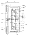
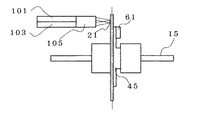
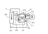
図1は本発明の実施例1における光減衰機能を備えた光スイッチ用アクチュエータ装置の装置平面図である。アクチュエータ装置は、光ファイバー部3とアクチュエータ部5から構成されており、この光ファイバー部3は、レンズの光軸対称に一対の光ファイバー101,103を配置した第1のコリメータレンズ組立105と、一対の光ファイバー107、109を配置した第2のコリメータレンズ組立111を配置し、その第1、及び第2のコリメータレンズ組立105,111を対向させて、第1及び第2のコリメータレンズ組立105、111は光ファイバー101と光ファイバー109、光ファイバー103と光ファイバー107とが互いに交差して光学接続するように配置して支持されており、1×1の光スイッチとしてはもちろん、2×2の光スイッチとしての機能も有する。
FIG. 1 is a plan view of an actuator device for an optical switch having an optical attenuation function in
アクチュエータ部5は、任意のサイズの筐体1内に配置されており、回転体7、第1の磁気回路9、第2の磁気回路11を備え、第1の磁気回路部9は電磁軟鉄等の磁性材料である第1のヨーク23と第1のヨーク23に巻回された第1の励磁用コイル25とで構成され、また、第2の磁気回路部11は電磁軟鉄等の磁性材料である第2のヨーク27と、第2のヨーク27に巻回された第2の励磁用コイル29とで構成されている。そして、第1のヨーク23及び第2のヨーク27は複数の部品を組み合わせて磁気的な結合がされている。
The
さらに、回転体7は、回転軸15を有し、この回転軸15にはローター磁石17と取付部45とが挿入され固定されている。また、取付部45には反射面(図示せず)を有する遮蔽板19と、熱移動手段としてのペルチェ素子61とが取り付けられている。さらに、遮蔽板19には温度検出手段としての白金測温抵抗体69が接着等で固定されている。また、回転軸15は底面41に設けられた回転軸保持部43と、軸押さえバネ13とで挟持されることによって、回転軸保持部43に回転自在に支持されている。更に、回転軸15は、その一端がブロック47に付き当たり、他端がスラストバネ49により一定圧を加えられることで、スラスト方向に支持されている。
Further, the
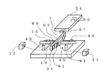
次に、遮蔽板19の反射面が光経路に挿入された状態をとるための回転規制構造について、図2の回転体斜視図および図3の磁気回路展開模式図を用いて説明する。なお、ローター磁石17は図3に示す方向に2極に着磁されているとする。また、符号21は回転体に設けられた反射面であり、符号35は光経路である。
Next, the rotation restricting structure for taking the state where the reflecting surface of the shielding
第1のヨーク23の一端31はローター磁石17のN極近傍に位置し、他端33はローター磁石17のS極近傍に位置している。回転軸保持部43の上端面には上方に開いたV溝などの凹部が形成され、その凹部に回転軸15がのることで、回転軸15は回転保持部43上に回転自在に支持される。更に、この回転軸15は軸押さえバネ13によって上から押さえつけられ、回転保持部43の凹部から上方に抜け出ることが妨げられている。
One
さらに、回転体7を構成する取付部45の回転体の一端53と接触できる位置に回転規制板の一端57が配設されている。回転体7を構成する取付部45の回転体の一端53が、回転規制板51の一端57と接触して第1の姿勢となる。
Further, one
そして、ローター磁石17のN極から生じた磁束は、空隙を通り最も近くにある磁性体の第1のヨーク23の一端31に流れ込み、第1のヨーク23を通り第1のヨーク23の
他端33へ向かって流れ、第1のヨーク23の他端33から空隙を通りローター磁石17のS極へと流れることにより閉磁路が形成され、ローター磁石17と第1のヨーク23との間に磁気吸引力が生じることで、回転体7は第1の姿勢に自己保持される。回転体7が第1の姿勢に保持された状態では、光ファイバーを通過する光経路35の光を、反射面21によって反射する状態を保持する事が出来る。
Then, the magnetic flux generated from the N pole of the
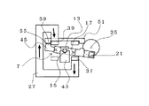
次に、ローター磁石17を含む回転体7が第2の姿勢に自己保持されている状態を図4の磁気回路展開模式図を用いて説明する。なお、ローター磁石17は図に示す方向に2極に着磁されているとする。
Next, a state in which the
第2のヨーク27の一端37はローター磁石17のN極近傍に位置し、他端39はローター磁石17のS極近傍に位置している。回転軸保持部43の上端面には上方に開いたV溝などの凹部が形成され、その凹部に回転軸15が載ることで、回転軸15は回転保持部43上に回転自在に支持される。更に、この回転軸15は軸押さえバネ13によって上から押さえつけられ、回転保持部43の凹部から上方に抜け出ることが妨げられている。
One
さらに、回転体7を構成する取付部45の回転体の他端55と接触できる位置に回転規制板の他端59が配設されている。回転体7を構成する取付部45の回転体の他端55が、回転規制板51の他端59と接触して第2の姿勢となる。
Furthermore, the
そして、ローター磁石17のN極から生じた磁束は、空隙を通り最も近くにある磁性体の第2のヨーク27の一端37へと流れ、第2のヨーク27を通り第2のヨーク27の他端39へ向かって流れ、第2のヨーク27の他端39から空隙を通りローター磁石17のS極へと流れることにより閉磁路が形成され、ローター磁石17と第2のヨーク27との間に磁気吸引力が生じることで、回転体7は第2の姿勢に自己保持される。回転体7が第2の姿勢に保持された状態では、光ファイバーを通過する光経路35の光を透過させる状態に保持することが出来る。このように回転体7の一方向に光軸を合わせて対向配置された一対の光ファイバーの隙間に遮蔽板19を挿脱させることによって光スイッチ機能が与えられる。また、遮蔽板19の熱変形手段を構成する白金測温抵抗体69とペルチェ素子61とで、遮蔽板19の温度を検出すると共に遮蔽板19の温度を調節し、遮蔽板19の反射面21の光軸と光ファイバーの光軸とのなす角度を変化させることによって可変光減衰機能が与えられる。
The magnetic flux generated from the N pole of the
この可変光減衰機能を与えるための熱変形手段について図5に示すブロック図を用いて説明する。反射面21を備える遮蔽板19は、取付部45によって保持されている。取付部45には白金測温抵抗体69が取り付けられており、回転体の姿勢確認はポジション検出器(フォトインタラプタ、フォトリフレクタ)を用いて行い、姿勢確認によって、反射モードである場合は白金測温抵抗体69に電流を流して、白金測温抵抗体69の抵抗値Rを検出し取付部45の温度を測定している。その温度を温度制御手段である演算部71によって基準温度と比較している。反射光を減衰させるときには、回路73によってペルチェ素子61に電流を流し、取付部45の温度を変化させる。そして、取付部45の温度を再度測定し、所望の減衰量が得られる温度まで繰り返し制御を行う。減衰量と温度の関係はあらかじめ相関データを用意しておく。
The thermal deformation means for providing this variable light attenuation function will be described with reference to the block diagram shown in FIG. The shielding
次に、遮蔽板19の反射面21の光軸と光ファイバーの光軸とのなす角度を変化させ可変光減衰機能を与える方法について説明する。まず、回転軸15に対して遮蔽板19の反射面21の角度を変化させる方法について図6(a)、図6(b)の回転体平面図を用いて説明する。
Next, a method for changing the angle between the optical axis of the reflecting
まず、ペルチェ素子61に電圧を印加していない状態を図6(a)を用いて説明する。
回転軸15に遮蔽板19、取付板45、ペルチェ素子61が固定されており、遮蔽板19は取付部45の取付面45bに接着等で固定されており、ペルチェ素子61は取付面45aに接着等で固定されている。この状態で遮蔽板19の反射面21は、回転軸15に対して略直角をなすように固定されている。
First, a state where no voltage is applied to the
The
そして、ペルチェ素子61に電圧印加し、電流を流した場合について図6(b)を用いて説明する。電流を流すと、ペルチェ素子61の接着面は温度変化し、取付部45に熱が移動し取付部45の温度を変化させる。すると、取付部45は熱膨張変化を起こす。ペルチェ素子61の接着面積は1mm×1mm程度であるため取付面45aに接着されている接着面積は小面積であり、一方、遮蔽板19が取付面45bに接着されている接着面積は大面積である。そのため、取付部45の取付面45bは広い面積の接着固定により膨張を拘束されており、取付面45aは狭い面積の接着固定のため、膨張の拘束は少なく、従って取付面45aと取付面45bとで膨張量に差が生じ、取付面45bより取付面45aのほうが膨張することから、取付部45は取付面45b側に傾斜するように変形することになる。従って遮蔽板は回転軸15に対しての傾斜θが生じることとなる。
A case where a voltage is applied to the
次に、反射面の傾きにより光減衰が生じることを図7(a)、図7(b)を用いて説明する。第1の光ファイバー101及び第2の光ファイバー103は、反射面21の同一方向に配置されている。そして、第1の光ファイバー101及び第2の光ファイバー103の先端には第1のコリメータレンズ組立105が備えられており、第1の光ファイバー101から出た平行光は第2の光ファイバーに103結合される。
Next, it will be described with reference to FIGS. 7A and 7B that light attenuation occurs due to the inclination of the reflecting surface. The first
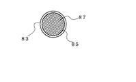
図7(a)の光経路に遮蔽板19が挿入された状態では、第1の光ファイバー101から出射された平行光は反射面21によって反射され、第2の光ファイバーに結合される。このときの結合の状態を図7(b)で示すと、入射光領域83に反射光85すべてが含まれ、結合光87は反射光85であるため、損失はほとんどない。このように、反射系を用いた構造で、遮蔽板19は光軸に対して垂直面を移動し、ペルチェ素子による傾斜θの変形量も極わずかのため、第1のコリメータレンズ組立105を反射面21に近接させることができるため、その距離は1mm以下にすることが可能である。このように平行光が移動する空間領域を狭くすることが出来ることから損失を少なくすることが出来、この時の損失は0.1dB以下にすることができる。
In the state where the shielding
次に、ペルチェ素子に電流を流した時の状態を図8(a)、図8(b)で説明すると、取付部45の温度が変化し、熱膨張をおこし変形することで、取付部45に取り付けられた遮蔽板19及び反射面21は光軸に対して角度θ傾くように変形をする。この状態では、反射面21によって反射された反射光85は第2の光ファイバー103の入射光領域83に対してずれた位置に結合し、結合光87は反射光85の一部分であるため、第2の光ファイバー103に入射する光の量が少なく、損失値が増え、光を減衰したことになる。この様に、反射面の傾き量を制御することで、光ファイバーに結合する結合光87の量を調整し、光の減衰量を制御することが出来る。
Next, the state when a current is passed through the Peltier element will be described with reference to FIGS. 8A and 8B. The temperature of the mounting
例えば取付部45の材質がジュラルミンであり、その線膨張係数を23.6×10⁻⁶/℃とし、取付部形状が図7(a)に示すような凸型をしているとき、温度が基準温度25度から75℃になると、反射面の変形角度は0.16度となり、損失が約3.5dBに減衰することが出来る、温度を基準温度±1度に制御し、これによって反射面の変形角度精度を0.02度以下とすることができる。この取付部の材質、形状を変化させることで、減衰量を設定することが可能である。
For example, when the material of the mounting
ここで、温度を検出するためにの温度検出手段である白金測温抵抗体について説明すると、白金測温抵抗体は金属の電気抵抗が温度変化に対して変化する性質を利用した測温抵
抗体の一種で、温度特性が良好で経時変化が少ない白金(pt)を測温素子に利用したセンサであるため、抵抗値と温度の関係がほぼ直線的であり、温度が高くなると抵抗値が上昇し、温度が低くなると抵抗値が下降するという特性を持っている。そして、再現性に優れている特徴を持つ。
Here, the platinum resistance temperature detector, which is a temperature detection means for detecting the temperature, will be described. The platinum resistance temperature detector is a resistance temperature detector utilizing the property that the electrical resistance of the metal changes with temperature change. This is a sensor that uses platinum (pt) with good temperature characteristics and little change over time as a temperature measuring element. Therefore, the relationship between the resistance value and temperature is almost linear, and the resistance value increases as the temperature increases. However, the resistance value decreases as the temperature decreases. And it has the feature which is excellent in reproducibility.
そして、白金測温抵抗体の測定抵抗値R1は、ペルチェ素子への通電が無い状態での温度における抵抗値とし、白金測温抵抗体に微弱電流を流して、白金測温抵抗体の抵抗値に応じた電位差が測定することで、白金測温抵抗体の抵抗値を知ることが出来る。そして、所望の減衰量を得ることができる温度に対する抵抗Rと測定抵抗値R1とを比較し、ほぼ等しい値であったならばペルチェ素子への通電は行わない。ここで、所望の減衰量を得るための温度に対する抵抗値Rと測定抵抗値R1との値が異なる場合、アクチュエータ装置の温度を変化させる必要があるため、ペルチェ素子に電流を流して温度を変化させる。この様に温度を制御することで、温度は±1度の範囲にすることができ、光減衰量は±0.2dB以内の精度で制御することが可能となる。 The measured resistance value R1 of the platinum resistance thermometer is a resistance value at a temperature when no current is supplied to the Peltier element, and a weak current is passed through the platinum resistance thermometer so that the resistance value of the platinum resistance thermometer is The resistance value of the platinum resistance thermometer can be known by measuring the potential difference in accordance with. Then, the resistance R with respect to the temperature at which a desired attenuation can be obtained is compared with the measured resistance value R1, and if the values are almost equal, the Peltier element is not energized. Here, when the resistance value R with respect to the temperature for obtaining the desired attenuation value and the measured resistance value R1 are different, it is necessary to change the temperature of the actuator device. Let By controlling the temperature in this way, the temperature can be in the range of ± 1 degree, and the light attenuation can be controlled with an accuracy within ± 0.2 dB.
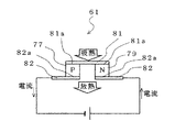
ペルチェ素子61の原理を図9で説明すると、二つの異種金属又は半導体を電気的に直列に接合して直流電流を流すことによって、その接合部分にジュール熱以外の吸熱及び発熱が発生する現象をペルチェ効果という。P型熱電半導体77とN型熱電半導体79を上電極81で接合し、N型熱電半導体79の方から直流電流を流すと、上側の接合面81aから下側の接合面82aへ熱を運び、このときに下側の電極82から十分な放熱を行うと、上側電極81において吸熱作用を連続的に得ることが出来る。逆にP型熱電半導体77の方から直流電流を流すと、下側の接合面82aから上側の接合面81aへ熱を運び、下側電極82において吸熱作用を連続的に得ることが出来る。
The principle of the
また、流す電流の大きさを変えることで吸熱量を変えることも出来る。ペルチェ素子の特徴としては、電流の方向を逆転させると吸熱面(低温側)と放熱面(高温側)を切り替えることが可能で、また、電流(電圧)の大きさを制御することで精密な温度コントロールが可能である。また、温度応答性が良いことと、小型、軽量、無振動、無騒音の特徴を持つ。 In addition, the amount of heat absorption can be changed by changing the magnitude of the flowing current. Peltier elements are characterized by switching the heat absorption surface (low temperature side) and the heat dissipation surface (high temperature side) by reversing the direction of the current, and controlling the magnitude of the current (voltage). Temperature control is possible. In addition, it has the characteristics of good temperature response, small size, light weight, no vibration, and no noise.
次に、回転体7が第1の姿勢から第2の姿勢へ移動した際に回転体7に作用する力について図10を用いて説明する。
Next, the force that acts on the
回転体7が図3に示すように第1の姿勢に保持されているとき、第1のヨーク23に巻回されている第1の励磁用コイル25に電流を流して磁束φを発生させ、第1のヨーク23の一端31をN極に、他端33をS極に励磁する。すると、第1のヨーク23の一端31のN極とローター磁石17のN極との間に反発力FNが生じる。同時に、第1のヨーク23の他端33のS極とローター磁石17のS極との間に反発力FSが生じる。これら反発力FS及びFNはローター磁石17を含む回転体7を回転軸15を中心に時計回転方向に回転させ、回転体7を第1の姿勢から第2の姿勢に向けて移動させることができる。
When the
この回転体7の時計回転方向の回転は、回転体7を構成する取付部45の回転体の他端55が回転規制板51の他端59と当接することで規制される。そして、回転体7が第1の姿勢から第2の姿勢に安定して移動するためには、十分な時間の通電状態を継続させることが必要である。例えば第1の姿勢から第2の姿勢に移動する時間が約5msecとしたとき通電時間を20msecにすることで、回転体7を第1の姿勢から第2の姿勢へ安定して移動することが可能となる。
The rotation of the
次に、回転体7を第2の姿勢から第1の姿勢へ移動した際に、回転体7に作用する力について図11を用いて説明する。回転体7が図9に示すように第2の姿勢に保持されてい
るとき、第2のヨーク27に巻回されている第2の励磁用コイル29に電流を流し磁束φを発生させ、第2のヨーク27の一端37をN極に、他端39をS極に、励磁する。すると、第2のヨーク27の一端37のN極とローター磁石17のN極との間に反発力FNが生じる。同時に、第2のヨーク27の他端39のS極とローター磁石17のS極との間に反発力FSが生じる。これら反発力FS及びFNはローター磁石17を含む回転体7を回転軸15を中心に反時計回転方向に回転させ、回転体7を第2の姿勢から図8に示すように第1の姿勢に向けて移動させることができる。
Next, the force that acts on the
この回転体7の反時計回転方向の回転は、回転体7を構成する取付部45の回転体の一端53が回転規制板51の一端57と当接することで規制される。そして、回転体7を第2の姿勢から第1の姿勢に安定して移動させるためには第2の励磁用コイル29には十分な時間通電させることが必要である。例えば第2の姿勢から第1の姿勢に移動する時間が約5msecとしたとき通電時間を20msecにすることで、回転体7を第2の姿勢から第1の姿勢へ安定して移動することが可能となる。
The rotation of the
また、本発明のアクチュエータ装置は、回転体7を回転させて様々な機能のスイッチングをすることができる。具体的には、回転体7自体又は回転体7とともに回転する従動体に遮蔽板19を配することで、その回転体7を第1の姿勢と第2の姿勢との間を回転させてスイッチとして機能させることが出来る。
In addition, the actuator device of the present invention can switch various functions by rotating the
ローター磁石17の材質は、SmCoあるいはNdFeBの希土類磁石等を用いることができ、回転軸15の軸方向に垂直な方向(図8における着磁方向)に2極に着磁されている。また、このローター磁石17の形状は、第1のヨーク23、第2のヨーク27と近接させることができ、第1のヨーク23または第2のヨーク27との間の閉磁路が形成できる形状であれば、いかなる形状であっても構わない。
The material of the
また、遮蔽板19はガラスまたはセラミック等の平滑面を有する板材の外形を加工して作製し、表面裏面ともに必要範囲に均等の反射率の高い材料を蒸着またはメッキ処理あるいは誘電体多層膜を形成し反射膜としての機能を有する反射面21を形成することができる。
Further, the shielding
さらに、本発明のアクチュエータ装置の回転体7は、回転対称形状とすることが可能なため、回転体7の重心と回転軸15の重心とを略一致させることが容易である。この様に回転体7の重心位置を略一致させることで、外部からの衝撃に対しアクチュエータ装置への影響を最小限にとどめることができる。なお、ここでの略一致とは、アクチュエータ部が衝撃を受けたとき、回転体7の重心と回転軸15の重心とのズレにより生じるモーメント等によって、スイッチ動作に与える影響が許容範囲内に収まる程度を意味している。
Furthermore, since the
そして、回転軸15のスラスト方向両端及び回転軸保持部43と接触する箇所、軸押さえバネ13と接触する箇所には、摩耗低減のためのコーティング処理、メッキ処理が施されていても良い。この場合、潤滑油を使う必要が無いので、反射面21への油膜の付着等の原因で生じる反射率の低下という信頼性低下要因を排除することができる。
Further, a coating process and a plating process for reducing wear may be performed on the thrust shaft both ends in the thrust direction, the portion in contact with the rotation
また、回転軸15と接触する相手部材表面にも摩耗低減のためのコーティング処理またはメッキ処理が施されていても良い。
Further, the surface of the mating member that contacts the
さらにこの回転軸15は回転軸保持部43及び軸押さえバネ13、スラストバネ49において、ラジアル方向、スラスト方向に保持される。この保持は、いずれも摩擦力が少ない軸受け構造をとることが可能である。そのため、本発明のアクチュエータ装置は、スイッチ動作に伴う回転角度が必要最小限に限定されて摺動箇所がこのラジアル方向2カ所及
びスラスト方向2カ所の微少範囲の接触のみとすることができるから、本発明のアクチュエータ装置を駆動する際に発生する摩擦による負荷を少なくすることができる。しかも、回転時における摩擦負荷は、ラジアル方向の摩擦力に回転軸半径を乗じた負荷トルクとして発生するが、回転半径は十分小さくすることができるため、少ないトルクで回転体7を回転させることができる。
Further, the
次に実施例2について図12のフロー図を用いて説明する。実施例1と異なる点は反射光量検出機構を設けた点である。 Next, Example 2 will be described with reference to the flowchart of FIG. The difference from the first embodiment is that a reflected light amount detection mechanism is provided.
回転体の姿勢確認で反射モードにある場合、反射光をビームスプリッターフィルターで一部分岐し、分岐光量をモニターダイオードで検出するなどの方法を用いて、反射光量のモニターを行い、そのとき測定される測定光量P1が所望の減衰量の時の目標光量P0と比較して差が0.2dBに入らない場合、反射面の傾きが適正ではないと判断し、取付部の熱膨張を制御し、反射面の傾きを適正にするように温度の制御を行う。 When the rotating body is in reflection mode, the reflected light is monitored by using a method such as partially splitting the reflected light with a beam splitter filter and detecting the branched light with a monitor diode. If the difference between the measured light amount P1 and the target light amount P0 when the desired light amount P1 is not 0.2 dB, it is determined that the inclination of the reflecting surface is not appropriate, the thermal expansion of the mounting portion is controlled, and the reflection is reflected. The temperature is controlled so that the inclination of the surface is appropriate.
このとき、まずペルチェ素子により取付部の温度を高温側に変化させてみる。そして、この時の測定光量P2を先ほどの目標光量P0と比較し、測定光量P1より所望の光量に近づいているのであれば、ペルチェ素子に流す電流の符号が問題無いと判断し、所望の光量との差が0.1dB以内になるまで繰り返す。また、測定光量P2が測定光量P1との比較で光量差が大きくなってしまった場合はペルチェ素子に流す電流の向きが逆向きであるとの判断を行い、逆向きの電流を流す。このようにし、目標光量P0と測定光量P1とが0.2dB以内になるまで制御を繰り返す。 At this time, first, the temperature of the mounting portion is changed to the high temperature side by the Peltier element. Then, the measured light quantity P2 at this time is compared with the target light quantity P0, and if the measured light quantity P1 is closer to the desired light quantity, it is determined that there is no problem with the sign of the current flowing through the Peltier element. Repeat until the difference is within 0.1 dB. Further, when the measured light amount P2 is larger than the measured light amount P1, a difference in the light amount is determined to determine that the direction of the current flowing through the Peltier element is reverse, and a reverse current is passed. In this way, the control is repeated until the target light amount P0 and the measured light amount P1 are within 0.2 dB.
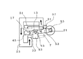
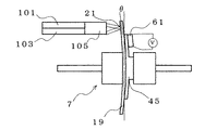
次に実施例3について図13を用いて説明する。実施例1と異なる点はペルチェ素子を回転規制板に配置した点である。 Next, Example 3 will be described with reference to FIG. The difference from the first embodiment is that the Peltier element is arranged on the rotation restricting plate.
図13は本発明のアクチュエータ装置を光スイッチとして用いたとき第1の姿勢におけるローター磁石近傍の断面図であり、回転軸保持部43と軸押さえバネ13を重ね合わせて図示したものである。なお、ローター磁石17は図13のN極、S極で示す方向に2極に着磁されているとする。
FIG. 13 is a cross-sectional view of the vicinity of the rotor magnet in the first posture when the actuator device of the present invention is used as an optical switch, and illustrates the rotating
第1のヨーク一端31はローター磁石17のN極近傍に位置し、第1のヨーク他端33はローター磁石17のS極近傍に位置している。回転軸15は回転軸保持部43と軸押さえバネ13とで挟み込まれることで回転自在に支持され、保持されている。そして、取付部45の回転体の一端53は回転規制板51の回転規制板の一端57と接触することで、第1の姿勢を得ている。
The first yoke one
ペルチェ素子61は、回転規制板の一端57近傍に位置し、このことで、ペルチェ素子61の温度変化を回転規制板の一端57に接触する取付部45の回転体の一端53に伝えることが出来、そのため取付部45の熱膨張、収縮が可能となり、反射面21の傾きを光減衰量が所望の減衰量になるように最適にすることができる。また、配線が容易であることと、配線部が可動しないため断線が起きず、更には配線のたわみによる負荷変動が無いため、消費電流値が安定しているという特徴を持つ。
The
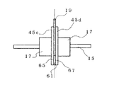
次に実施例4について図14を用いて説明する。図14は本発明のアクチュエータ装置の回転体平面図である。実施例1と異なる点はペルチェ素子61の放熱面65と吸熱面67とを挟み込むように2枚の取付部を配置し、遮蔽板は取付部によって挟み込むことで保
持されている点である。
Next, Example 4 will be described with reference to FIG. FIG. 14 is a plan view of the rotating body of the actuator device of the present invention. The difference from the first embodiment is that two attachment portions are arranged so as to sandwich the
回転軸15には遮蔽板19、取付部45c、取付部45d、ローター磁石17が挿入固定されており、ペルチェ素子61は軸方向に放熱面65、吸熱面67があるとしたとき、放熱面65と接触するように一方の取付部45cがあり、吸熱面67と接触するように他方の取付部45dがあり、遮蔽板19は一方の取付部45cと他方の取付部45dで挟み込むことで構成されている。このことによってペルチェ素子61の放熱面65の放熱により、一方の取付部45cの温度が上昇し、一方の取付部45cが膨張する、このとき、吸熱面67の吸熱により他方の取付部45dの温度が低下し、他方の取付部45dが収縮する。従って、遮蔽板19の片方で膨張、他方で収縮するため、より大きな材料変形を得ることが可能で、遮蔽板19の傾き角度も大きくすることができ、より広い減衰量を達成することが可能である。
When the shielding
1 筐体
3 光ファイバー部
5 アクチュエータ部
7 回転体
9 第1の磁気回路部
11 第2の磁気回路部
13 軸押さえバネ
15 回転軸
17 ローター磁石
19 遮蔽板
21 反射面
23 第1のヨーク
25 第1の励磁用コイル
27 第2のヨーク
29 第2の励磁用コイル
31 第1のヨーク一端
33 第1のヨーク他端
35 光経路
37 第2のヨーク一端
39 第2のヨーク他端
41 底面
43 回転軸保持部
45 取付部
47 ブロック
49 スラストバネ
51 回転規制板
53 回転体の一端
55 回転体の他端
57 回転規制板の一端
59 回転規制板の他端
61 ペルチェ素子
63 取付面
65 放熱面
67 吸熱面
69 白金測温抵抗体
71 演算部
73 回路
75 ポジション検出器
77 P型熱電半導体
79 N型熱電半導体
81 上電極
81a 上側の接合面
82 下電極
82a 下側の接合面
83 入射光領域
85 反射光
87 結合光
DESCRIPTION OF
Claims (7)
前記熱変形手段は、前記遮蔽板の温度を上昇または下降させる熱移動手段と、前記熱移動手段を制御する温度制御手段とを有し、前記遮蔽板の温度を調節することによって、前記遮蔽板の反射面の光軸と光ファイバーの光軸とのなす角度を変化させるように構成することで可変光減衰機能が与えられていることを特徴とするアクチュエータ装置。 A rotating body having a rotating shaft, a mounting portion fixed to the rotating shaft, a shielding plate fixed to the mounting portion and having a reflecting surface, a rotating shaft holding portion that rotatably supports the rotating shaft, and the rotation A rotation restricting plate for restricting the rotational position of the body, and a first posture in which one end of the rotating member is in contact with one end of the rotation restricting plate, or the other end of the rotating member is the other end of the rotation restricting plate. Each of the contacted second postures includes a posture holding means for self-holding, a driving means for moving the rotating body, and a thermal deformation means for the shielding plate, and aligns the optical axis in one direction of the rotating body. An actuator device that is provided with an optical switch function by inserting and removing the shielding plate into a gap between a pair of optical fibers disposed opposite to each other,
The thermal deformation means has a heat transfer means for raising or lowering the temperature of the shielding plate, and a temperature control means for controlling the heat transfer means, and adjusting the temperature of the shielding plate, thereby adjusting the shielding plate. An actuator device characterized in that a variable light attenuation function is provided by changing the angle formed by the optical axis of the reflecting surface of the optical fiber and the optical axis of the optical fiber.
The posture holding means includes a rotor magnet constituting a part of the rotating body, and first and second yokes extending from near one end of the rotor magnet to near the other end of the rotor magnet, When in the first posture or the second posture, a closed magnetic path is formed between the rotor magnet and the first or second yoke, so that the rotating body is moved to the first posture or the second posture. The actuator device according to claim 1, wherein the actuator device is held in two postures.
Priority Applications (1)
| Application Number | Priority Date | Filing Date | Title |
|---|---|---|---|
| JP2004037631A JP2005227637A (en) | 2004-02-16 | 2004-02-16 | Actuator device |
Applications Claiming Priority (1)
| Application Number | Priority Date | Filing Date | Title |
|---|---|---|---|
| JP2004037631A JP2005227637A (en) | 2004-02-16 | 2004-02-16 | Actuator device |
Publications (2)
| Publication Number | Publication Date |
|---|---|
| JP2005227637A true JP2005227637A (en) | 2005-08-25 |
| JP2005227637A5 JP2005227637A5 (en) | 2007-03-01 |
Family
ID=35002386
Family Applications (1)
| Application Number | Title | Priority Date | Filing Date |
|---|---|---|---|
| JP2004037631A Pending JP2005227637A (en) | 2004-02-16 | 2004-02-16 | Actuator device |
Country Status (1)
| Country | Link |
|---|---|
| JP (1) | JP2005227637A (en) |
Cited By (2)
| Publication number | Priority date | Publication date | Assignee | Title |
|---|---|---|---|---|
| CN113985599A (en) * | 2021-09-29 | 2022-01-28 | 无锡微奥科技有限公司 | Transmission-type optical switch, lighting device, and electronic apparatus |
| JP2022552600A (en) * | 2020-03-31 | 2022-12-19 | アクセリンク テクノロジーズ カンパニー リミテッド | Optical signal attenuator and optical signal transmission system |
-
2004
- 2004-02-16 JP JP2004037631A patent/JP2005227637A/en active Pending
Cited By (4)
| Publication number | Priority date | Publication date | Assignee | Title |
|---|---|---|---|---|
| JP2022552600A (en) * | 2020-03-31 | 2022-12-19 | アクセリンク テクノロジーズ カンパニー リミテッド | Optical signal attenuator and optical signal transmission system |
| JP7361206B2 (en) | 2020-03-31 | 2023-10-13 | アクセリンク テクノロジーズ カンパニー リミテッド | Optical signal attenuator and optical signal transmission system |
| CN113985599A (en) * | 2021-09-29 | 2022-01-28 | 无锡微奥科技有限公司 | Transmission-type optical switch, lighting device, and electronic apparatus |
| CN113985599B (en) * | 2021-09-29 | 2024-01-16 | 无锡微文半导体科技有限公司 | Transmission type optical switch, lighting device and electronic equipment |
Similar Documents
| Publication | Publication Date | Title |
|---|---|---|
| US6844952B2 (en) | Actuator-controlled mirror with Z-stop mechanism | |
| US5864643A (en) | Miniature 1XN electromechanical optical switch and variable attenuator | |
| US20060233061A1 (en) | Alignment features for heat assisted magnetic recording transducers | |
| US10730740B2 (en) | Microelectromechanical displacement structure and method for controlling displacement | |
| US4157861A (en) | Optical beam steering system | |
| Hafez et al. | Design, simulations and experimental investigations of a compact single mirror tip/tilt laser scanner | |
| WO2018138349A2 (en) | Device for tilting an optical element, particularly a mirror | |
| EP1083453B1 (en) | Reflection mirror type optical fiber switch | |
| JP2680820B2 (en) | Light switch | |
| US20060280421A1 (en) | Variable light attenuator | |
| FR3100400A1 (en) | MAGNETIC ACTUATOR AND MECHATRONIC SYSTEM | |
| JP3996414B2 (en) | Actuator device | |
| JP2005227637A (en) | Actuator device | |
| US20020150324A1 (en) | Optical switch and servo mechanism | |
| EP1377868B1 (en) | Method and apparatus for orienting a surface | |
| US20020076134A1 (en) | Methods and apparatuses for optical switches | |
| JP2005091531A (en) | Actuator apparatus | |
| JP2004258305A (en) | Actuator apparatus | |
| JP2005122112A (en) | Variable optical attenuator | |
| JP5163678B2 (en) | Galvano scanner | |
| JP2002502052A (en) | Small 1 × N electromechanical optical switch | |
| JP4364594B2 (en) | Optical device and manufacturing method thereof | |
| JP4073417B2 (en) | Optical head device | |
| JPH09325287A (en) | Actuator for variable wavelength optical filter module | |
| JPH0675136A (en) | Positioning assembling method for optical fiber terminal and optical component |
Legal Events
| Date | Code | Title | Description |
|---|---|---|---|
| A521 | Written amendment |
Free format text: JAPANESE INTERMEDIATE CODE: A523 Effective date: 20070111 |
|
| A621 | Written request for application examination |
Free format text: JAPANESE INTERMEDIATE CODE: A621 Effective date: 20070111 |
|
| A977 | Report on retrieval |
Free format text: JAPANESE INTERMEDIATE CODE: A971007 Effective date: 20081209 |
|
| A131 | Notification of reasons for refusal |
Free format text: JAPANESE INTERMEDIATE CODE: A131 Effective date: 20081216 |
|
| A02 | Decision of refusal |
Free format text: JAPANESE INTERMEDIATE CODE: A02 Effective date: 20090407 |