JP2005224794A - Atomizer assembly for hose end - Google Patents
Atomizer assembly for hose end Download PDFInfo
- Publication number
- JP2005224794A JP2005224794A JP2004278817A JP2004278817A JP2005224794A JP 2005224794 A JP2005224794 A JP 2005224794A JP 2004278817 A JP2004278817 A JP 2004278817A JP 2004278817 A JP2004278817 A JP 2004278817A JP 2005224794 A JP2005224794 A JP 2005224794A
- Authority
- JP
- Japan
- Prior art keywords
- valve
- exhaust
- rocker arm
- assembly
- housing
- Prior art date
- Legal status (The legal status is an assumption and is not a legal conclusion. Google has not performed a legal analysis and makes no representation as to the accuracy of the status listed.)
- Withdrawn
Links
Images


Classifications
-
- B—PERFORMING OPERATIONS; TRANSPORTING
- B05—SPRAYING OR ATOMISING IN GENERAL; APPLYING FLUENT MATERIALS TO SURFACES, IN GENERAL
- B05B—SPRAYING APPARATUS; ATOMISING APPARATUS; NOZZLES
- B05B15/00—Details of spraying plant or spraying apparatus not otherwise provided for; Accessories
-
- B—PERFORMING OPERATIONS; TRANSPORTING
- B05—SPRAYING OR ATOMISING IN GENERAL; APPLYING FLUENT MATERIALS TO SURFACES, IN GENERAL
- B05B—SPRAYING APPARATUS; ATOMISING APPARATUS; NOZZLES
- B05B7/00—Spraying apparatus for discharge of liquids or other fluent materials from two or more sources, e.g. of liquid and air, of powder and gas
- B05B7/02—Spray pistols; Apparatus for discharge
- B05B7/12—Spray pistols; Apparatus for discharge designed to control volume of flow, e.g. with adjustable passages
- B05B7/1209—Spray pistols; Apparatus for discharge designed to control volume of flow, e.g. with adjustable passages the controlling means for each liquid or other fluent material being manual and interdependent
-
- B—PERFORMING OPERATIONS; TRANSPORTING
- B05—SPRAYING OR ATOMISING IN GENERAL; APPLYING FLUENT MATERIALS TO SURFACES, IN GENERAL
- B05B—SPRAYING APPARATUS; ATOMISING APPARATUS; NOZZLES
- B05B7/00—Spraying apparatus for discharge of liquids or other fluent materials from two or more sources, e.g. of liquid and air, of powder and gas
- B05B7/24—Spraying apparatus for discharge of liquids or other fluent materials from two or more sources, e.g. of liquid and air, of powder and gas with means, e.g. a container, for supplying liquid or other fluent material to a discharge device
- B05B7/2402—Apparatus to be carried on or by a person, e.g. by hand; Apparatus comprising containers fixed to the discharge device
- B05B7/244—Apparatus to be carried on or by a person, e.g. by hand; Apparatus comprising containers fixed to the discharge device using carrying liquid for feeding, e.g. by suction, pressure or dissolution, a carried liquid from the container to the nozzle
- B05B7/2443—Apparatus to be carried on or by a person, e.g. by hand; Apparatus comprising containers fixed to the discharge device using carrying liquid for feeding, e.g. by suction, pressure or dissolution, a carried liquid from the container to the nozzle the carried liquid and the main stream of carrying liquid being brought together downstream of the container before discharge
-
- Y—GENERAL TAGGING OF NEW TECHNOLOGICAL DEVELOPMENTS; GENERAL TAGGING OF CROSS-SECTIONAL TECHNOLOGIES SPANNING OVER SEVERAL SECTIONS OF THE IPC; TECHNICAL SUBJECTS COVERED BY FORMER USPC CROSS-REFERENCE ART COLLECTIONS [XRACs] AND DIGESTS
- Y10—TECHNICAL SUBJECTS COVERED BY FORMER USPC
- Y10T—TECHNICAL SUBJECTS COVERED BY FORMER US CLASSIFICATION
- Y10T137/00—Fluid handling
- Y10T137/8593—Systems
- Y10T137/86292—System with plural openings, one a gas vent or access opening
- Y10T137/86324—Tank with gas vent and inlet or outlet
- Y10T137/86332—Vent and inlet or outlet in unitary mounting
Abstract
Description
本発明は、加圧されたキャリア液体(搬送液体)の送出源へ接続されるようになっている噴霧器組立体に一般的に関するものであり、また弁開放位置においてキャリア液体の流れにサイフォン式に移される液体薬品の容器へ取付けられるようになっている。 The present invention relates generally to a nebulizer assembly adapted to be connected to a source of pressurized carrier liquid (conveying liquid) and siphonically to the flow of carrier liquid in a valve open position. It can be attached to the container of the liquid chemical to be transferred.
べンチュリ作用によって、または空気間隙の形成により、ある量の液体薬品を水路中に引き込むために、液体薬品の容器へ取付けられ、かつホースの端部へ連結されるように配置される種々の噴霧器組立体がある。手動の回転弁が、キャリア液体入口と製品入口が接続されると噴霧器を作動するように、製品入口とキャリア液体入口の接続を外して噴霧器を作動停止するように、およびキャリア液体流路が送出部へ接続して水洗を実施するようになっている。 Various atomizers that are attached to the liquid chemical container and arranged to be connected to the end of the hose to draw a quantity of liquid chemical into the water channel by venturi or by formation of an air gap There is an assembly. A manual rotary valve activates the sprayer when the carrier liquid inlet and product inlet are connected, disconnects the product inlet from the carrier liquid inlet and deactivates the sprayer, and the carrier liquid flow path delivers It is designed to be connected to the department and washed with water.
液体薬品がキャリア液体流中に引き込まれる間に、噴霧器のON位置において容器を大気に排気することが重要である。 It is important to evacuate the container to the atmosphere at the ON position of the nebulizer while the liquid chemical is drawn into the carrier liquid stream.
噴霧器ハウジングの弁室内の回転弁上に排気制御部材が設けられ、たとえば、特許文献1および特許文献2によれば、前記制御部材により、たとえば、米国特許願第60/515,416号において指摘されるように、弁が開放位置にある間、薬品容器中にキャリア液体の好ましくない浸入を許すが、これは勿論最も好ましくないものである。そのような浸入が継続されるならば、選択された薬品で庭木と芝生を噴霧するときに薬品が希釈されて、その有効性を失うことになる。上述の米国特許願第60/515,416号に記載される発明は、キャリア液体/液体薬品接続部を、排気部および排気制御部材から隔離して上述の希釈の問題を避けることによりこの問題を解決している。 An exhaust control member is provided on the rotary valve in the valve chamber of the sprayer housing. For example, according to Patent Document 1 and Patent Document 2, the control member indicates, for example, in US Patent Application No. 60 / 515,416. As such, while the valve is in the open position, it allows undesired entry of the carrier liquid into the drug container, which is of course the least preferred. If such intrusion continues, the chemical will be diluted when spraying garden trees and lawn with the selected chemical, losing its effectiveness. The above described US patent application Ser. No. 60 / 515,416 addresses this problem by isolating the carrier liquid / liquid chemical connection from the exhaust and exhaust control member to avoid the dilution problem described above. It has been solved.
使用と組立が容易であり、しかも確実な排気制御の実現に高い有効性がある単純な構造の排気の他の解決策を提供して、排気開放状態において容器中へのキャリア液体の浸入の可能性を避けることが望ましいであろう。
したがって本発明の目的は、回転弁を有するホース端部噴霧器組立体を提供することにある。 Accordingly, it is an object of the present invention to provide a hose end sprayer assembly having a rotary valve.
前記回転弁は、噴霧器のON位置において開放する液体製品入口へキャリア液体入口流路を接続し、かつ同時に、噴霧器ハウジング上に位置決めされる排気部を開放する。外部排気制御部材が、ハウジング上に取付けられ、および弁のONとOFFの位置にある間に排気部をそれぞれ開放と閉止するように弁により係合自在である。外部排気制御部材は、排気通路の前後に移動できるように排気シールを有するロッカーアームと、および排気のONとOFFとの位置間で枢軸回転できるように、その回転移動中に弁上の突出部と係合するカム表面または同様な表面とを備えることができる。
他の目的および変形態様は、添付図面と連係してなされるときに本発明に従って実施できる。
The rotary valve connects the carrier liquid inlet channel to the liquid product inlet that opens in the ON position of the sprayer, and simultaneously opens the exhaust located on the sprayer housing. An external exhaust control member is mounted on the housing and is engageable by the valve to open and close the exhaust portion while the valve is in the ON and OFF positions, respectively. The external exhaust control member includes a rocker arm having an exhaust seal so that it can move back and forth in the exhaust passage, and a protrusion on the valve during its rotational movement so that it can pivot between the ON and OFF positions of the exhaust. A cam surface or similar surface that engages.
Other objects and variations can be made in accordance with the present invention when made in conjunction with the accompanying drawings.
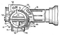
幾つかの図面の全体を通して同様な図面参照番号が同様で対応する部材を指す図面をここで参照すると、本発明に係る噴霧器組立体が、図1、3、5と6において全体的に10で表示される。ただし図1と3においては、明確にするために回転弁11(図5、6)が図示されないし、また図1においては、明確にするために排気制御部材12(図2)が図示されない。 Referring now to the drawings in which like reference numerals refer to corresponding and corresponding parts throughout the several views, a nebulizer assembly according to the present invention is generally designated 10 in FIGS. Is displayed. However, in FIGS. 1 and 3, the rotary valve 11 (FIGS. 5 and 6) is not shown for clarity, and in FIG. 1, the exhaust control member 12 (FIG. 2) is not shown for clarity.
噴霧器組立体は、全体がここに参照として組込まれ、かつ前記特許文献3に示されるものと同様なハウジング13を備える。ハウジングには、その自由端部にサイフォン防止組立体15を有する導管14が備えられ、前記組立体15は、庭園用ホース(図示せず)または同様なものの端部へ組立体10を取付ける閉止部材(クロージャー)16を備える。ハウジングは、噴霧器組立体を容器(図示せず)の頸部21上で支承するために、容器閉止部材(クロージャー)19上で環状縁部18により係合自在な端部鍔状部材17をさらに備える。
The nebulizer assembly is incorporated herein by reference in its entirety and includes a
噴霧器組立体は、裏壁23を有するか、または有しない横方向内腔22(図4)をさらに備える。またハウジングは、以下にさらに説明するように、弁のONとOFFの位置を使用者が決定するのを容易にするために、図示のようなONとOFFのマーキングを備える円弧状の壁24を有することができる。
The nebulizer assembly further comprises a lateral lumen 22 (FIG. 4) with or without a
上述の噴霧器ハウジングは、前記特許文献3に開示されるものとほぼ同一である。また回転弁11は、同様に、そこに開示されるものとほぼ同一である。回転弁は、図5、6において所定位置に組込まれるのが示され、および26におけるように一端部で閉じることができる円筒形外壁25を備える。前記弁は、円筒形弁の直径に沿って延びるキャリア液体ダクト27、およびダクト27と開放連通する半径方向に延びる液体薬品入口ダクト28を有する。回転弁は同様に、弁を中心軸の回りに回転するために操作者により掴まれる回しハンドル29または同様なもの、および回転弁が図5と6に示されるように所定位置に組込まれるとき、半径方向外側へ延び、かつ壁24の部分的に下にあることができる指示棒31または同様なものを有する。
The above-described sprayer housing is substantially the same as that disclosed in Patent Document 3. The
回転弁は、そのONとOFFの位置間において手動で回転自在である。図6に示されるON位置において、開放庭園用ホースからの加圧された水が、導管14内に位置決めされる入口流路と、およびキャリア液体ダクト27を通過し、前記ダクト27は、全体の開示がここで参照として特に組込まれる上述した米国特許願第60/515,416号に開示されるように、内径が次第に減少するように形成されるベンチュリ部分を備えて、キャリア液体がそれに沿って流れる間に回転弁のON位置においてキャリア液体の流れを抑制する。入口ダクトは同様に、ベンチュリ部分の最小径よりも大きいほぼ一定の径のチューブ部分を有する。そのような部分間の接合点において、ハウジングからの入口ダクトまたは入口ポート(図示せず)が、前記接合点と連通する。そのようなダクトまたはポートは、前記特許文献3に示されるように、容器中に延びる浸漬チューブと連通する。したがって、キャリア液体がベンチュリ部分に沿って流れると、キャリア液体圧力が低下するので、薬品が浸漬チューブから、薬品入口ダクト/ポートを通してキャリア液体流中に吸込まれる。キャリア液体流中に吸込まれた薬品は、かくしてキャリア液体と混合して、図6の位置においてダクト27と水平方向に整合する、ハウジング内に位置決めされる送出流路(前記特許文献3に示される)の開放端部を通して送出される。混合された液体の流れを目標へ向けて送る回転自在のノズル(図示せず)を、噴霧器組立体の前方端部に設けることができる。かくして回転弁は、導管14内のキャリア液体入口流路と、および図6のON位置においてハウジング内に位置決めされる送出流路を有するハウジング内に位置決めされる液体製品入口ポートとを相互接続するために、その内腔内で選択的に回転自在である。またその弁は、キャリア液体入口流路が液体製品入口ポートと接続されない図5のOFF位置まで選択的に回転自在である。さらに、回転弁のそのような選択的なON/OFFの位置決めの詳細は、前記特許文献3および上述した米国特許願第60/515,416号において説明される。したがって、そのさらに詳細な説明は、ここでは記載しない。
The rotary valve is manually rotatable between its ON and OFF positions. In the ON position shown in FIG. 6, pressurized water from an open garden hose passes through an inlet channel positioned in the
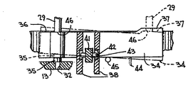
本発明によれば、ハウジング内に設けられる排気ポート32(図1と7)が、容器の内部と直接連通し、かつ大気に開放するように容器排気手段が設けられる。本発明に係る排気制御手段は、図2に詳細が示される制御部材33を設けることにより、回転弁とその横方向内腔の外側にあり、制御部材33は、一端部において排気プラグシール35を有する円弧状ロッカーアーム34の形態にできる。また外側縁部36におけるロッカーアームは、相対端部近くに形成されるカム表面37を有することができる。
According to the present invention, the container exhaust means is provided so that the exhaust port 32 (FIGS. 1 and 7) provided in the housing communicates directly with the interior of the container and is open to the atmosphere. The exhaust control means according to the present invention is provided outside the rotary valve and its lateral lumen by providing a
ロッカーアームは、その端部間に、一対の外側へ延びる離間した取付けフランジ38を設けて、回転弁を受容する横方向内腔22を形成する横方向円筒形壁39に平行にハウジングの外側へ円弧状ロッカーアームを取付けることができる。またハウジングには、あご付き外端部を備えた突出部41を設けることができ、その突出部は、図5と6の排気制御部材が組込まれた位置において、かつ図7に詳細が示されるように、あご部42がフランジ38の内壁における回り止め43内に延びるようにフランジ38間に延びるので、組立中に円弧状ロッカーアームを所定位置に迅速かつ簡単にしかも確実にスナップ嵌めするのが容易になる。そのような位置においてプラグシール35が、排気ポート32と同軸になるように配置される(図7)。またロッカーアームの内側縁部44は、所定位置に取付けられると、ハウジングの円筒形壁39から半径方向外側へ延びる枢着ピン45へ押付けられる。
The rocker arm is provided with a pair of outwardly extending
弁を図6のON位置まで回転した作動において、ハウジングの円筒形壁39の半径方向外側へ延びるハンドル29の下側46は、図7において仮想輪郭で図示されるようにカム表面37へ押付けられるので、排気制御部材のロッカーアーム44が枢着ピン45の回りに枢軸回転して、その端部が下方へ、かつ相対端部が上方へ移動し、その結果、排気プラグシール35は、排気ポート32から離れて、排気ポートを開放する。かくして弁のON位置において、容器の内部と連通する排気ポートは、大気に開放されるので、流れるキャリア液体のベンチュリ作用により容器から引込まれる製品が、空気により置き換えられ容器の圧潰を避けることができるし、またそうでない場合に噴霧器の円滑な作動の妨害を避けることができる。また操作者が弁を図5のOFF位置まで回転すると、ハンドル張出しの下側46はロッカーアームの外側縁部36へ押付けられて、図7において実線輪郭で示されるように枢着ピン45の回りに下方へ枢軸回転するので、ここで排気プラグシール35は、保管、輸送および不使用の状態中に閉じられる排気ポートを封止するように排気ポートの上に載るハウジング13と封止係合して、弁をOFF位置にした状態で排気ポート32を通しての製品の漏れを避ける。ロッカーアームの取付けフランジ38により、弁のONとOFFとの位置間のロッカーアームの上述の枢軸回転が妨害無しに容易になる。
In operation with the valve rotated to the ON position of FIG. 6, the
本発明に係る排気制御手段は、回転弁に対して、かつ弁が中で受容されるハウジングの横方向内腔に対して完全に外部にある。ロッカーアームは、組立中に噴霧器ハウジングの外側へ所定位置に単純にスナップ嵌めされるので、噴霧器組立体の屋外使用中に外れる可能性が無く所定位置に確実に取付けられながら、上述のようにピン45の回りに枢軸回転できる。回転弁、すなわち回しハンドルまたは同様なものの張出しの下側は、選択された回転移動時に弁のONとOFFの位置にある間、排気をそれぞれ開放と閉止できるために、一端部においてロッカーアームの外側縁部36へ、および前記カム表面へ押付けられるように配置される。本発明の範囲内で、ロッカーアームは同様に、ロッカーアームの同一の移動を達成しながら、カム表面が図示されるものから相対端部にあるように配置できることが指摘される。また他の既知の同等機構は、そのような機構が、弁ONと弁OFFの位置にある間に排気を開放と閉止するように回して弁により作動される限り、ロッカーアーム、およびアームカムとカム従動子に代替えできるであろうことは本発明の範囲内であり、また排気制御手段は、回転弁に対して、かつその横方向内腔に対して完全に外部にある。たとえば、ロッカーアームは、ピン45の軸に直交する軸の回りに枢軸回転するように配置できるであろう。または、本発明の範囲内の他の既知の手法を実施できるであろう。
The exhaust control means according to the invention is completely external to the rotary valve and to the lateral lumen of the housing in which the valve is received. The rocker arm is simply snapped into place outside the sprayer housing during assembly, so that the pin can be pinned as described above while still securely attached in place without the possibility of detaching during outdoor use of the sprayer assembly. It can pivot about 45. The underside of the overhang of the rotary valve, i.e. the turning handle or the like, can be opened and closed respectively at one end of the rocker arm so that the exhaust can be opened and closed while the valve is in the ON and OFF position during the selected rotational movement. It is arranged to be pressed against the
明らかに、本発明の多くの他の変更態様および変形態様は、上述の教示に鑑みて実施可能である。したがって、添付の特許請求の範囲内で、本発明は具体的に上述したもの以外で実施できることが分かる。 Obviously, many other modifications and variations of the present invention are possible in light of the above teachings. Therefore, it will be appreciated that, within the scope of the appended claims, the invention may be practiced other than as specifically described above.
10 噴霧器組立体
11 回転弁
12 排気制御部材
13 ハウジング
14 導管
15 サイフォン防止組立体
16 閉止部材(クロージャー)
17 端部鍔状部材
18 環状縁部
19 容器閉止部材(クロージャー)
21 頸部
22 横方向内腔
23 裏壁
24 円弧状の壁
25 円筒形外壁
27 キャリア液体ダクト
28 薬品入口ダクト
29 回しハンドル
31 指示棒
32 排気ポート
33 制御部材
34 ロッカーアーム
35 排気プラグシール
36 外側縁部
37 カム表面
38 取付けフランジ
39 円筒形壁
41 突出部
42 あご部
43 回り止め
44 内側縁部
45 枢着ピン
46 下側
DESCRIPTION OF
17 End-
21
Claims (24)
弁ハンドルは、排気プラグシールを排気通路の前後に動かすようにロッカーアームと係合することを特徴とする請求項9記載の噴霧器組立体。 The sprayer assembly of claim 9, wherein the exhaust plug assembly includes a rocker arm and an exhaust plug seal, and wherein the valve handle engages the rocker arm to move the exhaust plug seal back and forth in the exhaust passage. Solid.
20. A sprayer assembly according to claim 19, wherein the valve comprises means for forming a cam follower that engages the cam surface to move the rocker arm to an exhaust release position.
Applications Claiming Priority (1)
| Application Number | Priority Date | Filing Date | Title |
|---|---|---|---|
| US10/777,076 US7255293B2 (en) | 2004-02-13 | 2004-02-13 | Hose-end sprayer assembly |
Publications (2)
| Publication Number | Publication Date |
|---|---|
| JP2005224794A true JP2005224794A (en) | 2005-08-25 |
| JP2005224794A5 JP2005224794A5 (en) | 2007-09-06 |
Family
ID=34701371
Family Applications (1)
| Application Number | Title | Priority Date | Filing Date |
|---|---|---|---|
| JP2004278817A Withdrawn JP2005224794A (en) | 2004-02-13 | 2004-09-27 | Atomizer assembly for hose end |
Country Status (22)
| Country | Link |
|---|---|
| US (1) | US7255293B2 (en) |
| EP (1) | EP1563913B1 (en) |
| JP (1) | JP2005224794A (en) |
| KR (1) | KR20050081837A (en) |
| CN (1) | CN1654130A (en) |
| AR (1) | AR045288A1 (en) |
| AT (1) | ATE353251T1 (en) |
| AU (1) | AU2004224887A1 (en) |
| BR (1) | BRPI0404377A (en) |
| CA (1) | CA2477016A1 (en) |
| CO (1) | CO5610004A1 (en) |
| CZ (1) | CZ2004886A3 (en) |
| DE (1) | DE602004004628T2 (en) |
| ES (1) | ES2280910T3 (en) |
| HK (1) | HK1080024A1 (en) |
| HU (1) | HUP0401664A2 (en) |
| NZ (1) | NZ534649A (en) |
| PL (1) | PL369694A1 (en) |
| SG (1) | SG114668A1 (en) |
| SI (1) | SI21694A (en) |
| SK (1) | SK3152004A3 (en) |
| TW (1) | TWI257880B (en) |
Families Citing this family (28)
| Publication number | Priority date | Publication date | Assignee | Title |
|---|---|---|---|---|
| US7188786B2 (en) * | 2004-10-28 | 2007-03-13 | Meadwestvaco Corporation | Hose-end sprayer assembly |
| EP1930084B1 (en) | 2006-12-05 | 2009-06-03 | SATA GmbH & Co. KG | Vent for the gravity cup of a paint spray gun |
| US20090119985A1 (en) * | 2007-11-10 | 2009-05-14 | Theo Duncan | Liquid Fertilizer, Weed Killer, and Pesticide Application Device Using Exchangeable Containers Connected to an Irrigation System |
| CN101970127B (en) | 2008-03-12 | 2014-11-12 | 杰弗里·D·福克斯 | Disposable spray gun cartridge |
| DE202008014389U1 (en) | 2008-10-29 | 2010-04-08 | Sata Gmbh & Co. Kg | Gravity cup for a paint spray gun |
| US20100126608A1 (en) * | 2008-11-22 | 2010-05-27 | Theo Duncan | Liquid fertilizer, weed killer, and pesticide application device using exchangeable containers connected to a hose bib |
| DE102009032399A1 (en) | 2009-07-08 | 2011-01-13 | Sata Gmbh & Co. Kg | Spray Gun |
| DE202010007355U1 (en) | 2010-05-28 | 2011-10-20 | Sata Gmbh & Co. Kg | Nozzle head for a spraying device |
| EP2646166B1 (en) | 2010-12-02 | 2018-11-07 | SATA GmbH & Co. KG | Spray gun and accessories |
| US10189037B2 (en) | 2011-06-30 | 2019-01-29 | Sata Gmbh & Co. Kg | Easy-to-clean spray gun, accessories therefor, and mounting and dismounting methods |
| EP2589821B1 (en) * | 2011-11-03 | 2017-08-02 | Heraeus Medical GmbH | Apparatus and method for the generation of vacuum for vacuum cementing systems |
| CA155474S (en) | 2013-09-27 | 2015-08-27 | Sata Gmbh & Co Kg | Spray gun |
| DE202013105779U1 (en) | 2013-12-18 | 2015-03-19 | Sata Gmbh & Co. Kg | Air nozzle termination for a paint spray gun |
| CN110560285B (en) | 2014-07-31 | 2021-05-18 | 萨塔有限两合公司 | Spray gun and method for manufacturing same |
| CA159961S (en) | 2014-07-31 | 2015-07-17 | Sata Gmbh & Co Kg | Spray gun |
| USD758537S1 (en) | 2014-07-31 | 2016-06-07 | Sata Gmbh & Co. Kg | Paint spray gun rear portion |
| USD768820S1 (en) | 2014-09-03 | 2016-10-11 | Sata Gmbh & Co. Kg | Paint spray gun with pattern |
| DE102015006484A1 (en) | 2015-05-22 | 2016-11-24 | Sata Gmbh & Co. Kg | Nozzle arrangement for a spray gun, in particular paint spray gun and spray gun, in particular paint spray gun |
| DE102015016474A1 (en) | 2015-12-21 | 2017-06-22 | Sata Gmbh & Co. Kg | Air cap and nozzle assembly for a spray gun and spray gun |
| CN205995666U (en) | 2016-08-19 | 2017-03-08 | 萨塔有限两合公司 | Spray gun and its trigger |
| CN205966208U (en) | 2016-08-19 | 2017-02-22 | 萨塔有限两合公司 | Hood subassembly and spray gun |
| US10247313B2 (en) * | 2017-06-29 | 2019-04-02 | Tao-Pao Chien | Spray gun and adjustment valve thereof |
| US10240328B1 (en) * | 2017-09-12 | 2019-03-26 | Tracey Estelhomme | Dual provision shower head |
| DE102018118737A1 (en) | 2018-08-01 | 2020-02-06 | Sata Gmbh & Co. Kg | Nozzle for a spray gun, nozzle set for a spray gun, spray guns and method for producing a nozzle for a spray gun |
| WO2018184636A2 (en) | 2018-08-01 | 2018-10-11 | Sata Gmbh & Co. Kg | Set of nozzles for a spray gun, spray gun system, method for embodying a nozzle module, method for seelcting a nozzle module from a set of nozzles for a paint job, selection system and computer program product |
| DE102018118738A1 (en) | 2018-08-01 | 2020-02-06 | Sata Gmbh & Co. Kg | Base body for a spray gun, spray guns, spray gun set, method for producing a base body for a spray gun and method for converting a spray gun |
| US20210105934A1 (en) * | 2019-10-11 | 2021-04-15 | Seth Inman | Mobile Aqueous Chemical Injection And Application Apparatus |
| USD980069S1 (en) | 2020-07-14 | 2023-03-07 | Ball Corporation | Metallic dispensing lid |
Family Cites Families (43)
| Publication number | Priority date | Publication date | Assignee | Title |
|---|---|---|---|---|
| US1071432A (en) * | 1912-11-23 | 1913-08-26 | George J Kelley | Atomizer. |
| US2612403A (en) * | 1949-08-02 | 1952-09-30 | Wilbur A Burch | Device for mixing fluids |
| US2761734A (en) * | 1955-06-03 | 1956-09-04 | Farmer Alfred | Spray device |
| US3034731A (en) * | 1959-03-04 | 1962-05-15 | R E Chapin Mfg Works Inc | Back flow preventing valve assembly |
| US3186643A (en) * | 1963-03-04 | 1965-06-01 | Mario J Manetti | Spray gun having disk, diaphragm and plug construction |
| US3201049A (en) * | 1963-03-07 | 1965-08-17 | Hayes Spray Gun Company | Proportioning eductor |
| US3204875A (en) * | 1963-07-23 | 1965-09-07 | Allpro Products Inc | Spray head having a valve stem and disc-form check valve |
| US3333601A (en) * | 1963-08-05 | 1967-08-01 | Andrew F Lofgreen | Additive apparatus for supplying and mixing a controllably adjustable quantity of one or more additive materials to a flowing quantity of liquid |
| US3212716A (en) * | 1963-09-19 | 1965-10-19 | Mills Tool & Die Co Inc J | Materials dispensing shower head device |
| US3255972A (en) * | 1964-03-12 | 1966-06-14 | Hultgren | Disposable container |
| US3610535A (en) * | 1969-09-03 | 1971-10-05 | Mite Corp | Liquids mixing and selective delivery system |
| US3964689A (en) * | 1975-04-10 | 1976-06-22 | S. C. Johnson & Son, Inc. | Hose-end dispenser device |
| US4171070A (en) * | 1977-06-10 | 1979-10-16 | Samuel Colgate, Robert Ramey And Associates | Apparatus for inserting an additive liquid into a flowing fluid and discharging the resultant mixture |
| US4315601A (en) * | 1980-08-04 | 1982-02-16 | Brooker Steven A | Chemical injector |
| US4369921A (en) * | 1980-12-12 | 1983-01-25 | Acme Burgess, Inc. | Hose-end sprayer |
| US4349157A (en) * | 1981-01-30 | 1982-09-14 | Acme Burgess, Inc. | Hose-end sprayer |
| US4508272A (en) * | 1982-09-28 | 1985-04-02 | Lincoln Thompson | Hose end spray nozzle |
| US4475689A (en) * | 1982-12-09 | 1984-10-09 | R. M. Smith, Inc. | Variable dilution ratio hose-end sprayer |
| US4527740A (en) * | 1982-12-16 | 1985-07-09 | Chevron Research Company | Hose-end aspirator sprayer |
| US4595127A (en) * | 1984-05-21 | 1986-06-17 | Stoody William R | Self-contained fluid pump aerosol dispenser |
| US4736891A (en) * | 1986-07-28 | 1988-04-12 | Hunter-Melnor, Inc. | Aspiration-type sprayer |
| US4750674A (en) * | 1986-08-28 | 1988-06-14 | Hunter-Melnor, Inc. | Aspiration-type sprayer |
| US4901923A (en) * | 1988-10-11 | 1990-02-20 | Chevron Research Company | Variable dilution ratio hose-end aspirator sprayer |
| US5039016C1 (en) * | 1990-01-23 | 2001-03-13 | Hayes Products L P | Aspiration-type chemical sprayer |
| US5213264A (en) * | 1990-10-11 | 1993-05-25 | Chevron Research And Technology Company | Spraying device with a replaceable cartridge |
| US5213265A (en) * | 1991-03-18 | 1993-05-25 | Hayes Products L.P. | Single valve aspiration type sprayer |
| US5100059A (en) * | 1991-03-18 | 1992-03-31 | Hayes Products | Single valve aspiration type sprayer |
| US5356076A (en) * | 1993-03-29 | 1994-10-18 | Bishop Robert A | Shower soap dispenser for liquid soaps |
| US5320288A (en) * | 1993-05-24 | 1994-06-14 | Green Garden, Inc. | Hose-end spraying apparatus |
| US5383603A (en) * | 1993-06-22 | 1995-01-24 | Hayes Products L.P. | Aspiration-type sprayer |
| US5626291A (en) * | 1994-11-14 | 1997-05-06 | Flinn; Robert A. | Cleaning solution spraying system |
| WO1997039962A1 (en) * | 1996-04-22 | 1997-10-30 | Taplast S.P.A | Dosing cap for dispensing liquids |
| US5881955A (en) * | 1997-04-17 | 1999-03-16 | Monsanto Company | Spraying device |
| US5954273A (en) * | 1997-04-22 | 1999-09-21 | Minnesota Mining And Manufacturing Company | Spray assembly for high viscosity materials |
| US5954272A (en) | 1998-04-24 | 1999-09-21 | Liao; Yu Chung | Detergent/water mixing system for a water spray gun |
| US6425534B2 (en) * | 1998-11-05 | 2002-07-30 | Green Garden Products Company | Spraying apparatus having a sealing member with apertures |
| US6283385B1 (en) * | 1999-01-22 | 2001-09-04 | Griffin Llc | Method and apparatus for dispensing multiple-component flowable substances |
| US6267303B1 (en) * | 1999-09-27 | 2001-07-31 | Douglas W. Francis | Sprinkler system fertilizer injector |
| US6578776B1 (en) * | 2000-04-03 | 2003-06-17 | Hayes Products, Llc. | Single valve ready to use hose end sprayer |
| US6471141B2 (en) * | 2000-06-08 | 2002-10-29 | Dispensing Technologies, L.L.C. | Hose sprayer assembly |
| US6378785B1 (en) * | 2000-08-30 | 2002-04-30 | Saint-Gobain Calmar Inc. | Hose-end aspiration-type sprayer |
| US6772966B2 (en) * | 2002-04-10 | 2004-08-10 | Continental Afa Dispensing Company | Adjustable hose end sprayer nozzle |
| US7118049B2 (en) * | 2003-10-30 | 2006-10-10 | Meadwestvaco Corporation | Hose-end sprayer assembly |
-
2004
- 2004-02-13 US US10/777,076 patent/US7255293B2/en not_active Expired - Lifetime
- 2004-08-09 CA CA002477016A patent/CA2477016A1/en not_active Abandoned
- 2004-08-10 NZ NZ534649A patent/NZ534649A/en unknown
- 2004-08-11 SI SI200400226A patent/SI21694A/en not_active IP Right Cessation
- 2004-08-12 SK SK315-2004A patent/SK3152004A3/en unknown
- 2004-08-13 HU HU0401664A patent/HUP0401664A2/en unknown
- 2004-08-16 ES ES04254914T patent/ES2280910T3/en active Active
- 2004-08-16 AT AT04254914T patent/ATE353251T1/en not_active IP Right Cessation
- 2004-08-16 DE DE200460004628 patent/DE602004004628T2/en not_active Expired - Fee Related
- 2004-08-16 EP EP20040254914 patent/EP1563913B1/en active Active
- 2004-08-17 CZ CZ2004886A patent/CZ2004886A3/en unknown
- 2004-08-17 KR KR1020040064513A patent/KR20050081837A/en not_active Application Discontinuation
- 2004-08-20 SG SG200404690A patent/SG114668A1/en unknown
- 2004-08-20 PL PL04369694A patent/PL369694A1/en not_active Application Discontinuation
- 2004-08-20 BR BRPI0404377 patent/BRPI0404377A/en not_active IP Right Cessation
- 2004-08-20 AR ARP040102987 patent/AR045288A1/en not_active Application Discontinuation
- 2004-08-23 TW TW093125328A patent/TWI257880B/en not_active IP Right Cessation
- 2004-08-25 CO CO04083306A patent/CO5610004A1/en unknown
- 2004-09-27 JP JP2004278817A patent/JP2005224794A/en not_active Withdrawn
- 2004-10-25 CN CNA2004100859384A patent/CN1654130A/en active Pending
- 2004-10-26 AU AU2004224887A patent/AU2004224887A1/en not_active Abandoned
-
2006
- 2006-01-04 HK HK06100155.5A patent/HK1080024A1/en unknown
Also Published As
| Publication number | Publication date |
|---|---|
| EP1563913A2 (en) | 2005-08-17 |
| EP1563913B1 (en) | 2007-02-07 |
| CN1654130A (en) | 2005-08-17 |
| HK1080024A1 (en) | 2006-04-21 |
| NZ534649A (en) | 2005-12-23 |
| ATE353251T1 (en) | 2007-02-15 |
| US20050178854A1 (en) | 2005-08-18 |
| DE602004004628D1 (en) | 2007-03-22 |
| SG114668A1 (en) | 2005-09-28 |
| KR20050081837A (en) | 2005-08-19 |
| DE602004004628T2 (en) | 2007-11-22 |
| SI21694A (en) | 2005-08-31 |
| EP1563913A3 (en) | 2006-02-22 |
| SK3152004A3 (en) | 2005-09-08 |
| CZ2004886A3 (en) | 2005-09-14 |
| PL369694A1 (en) | 2005-08-22 |
| TWI257880B (en) | 2006-07-11 |
| BRPI0404377A (en) | 2005-09-27 |
| CA2477016A1 (en) | 2005-08-13 |
| HUP0401664A2 (en) | 2006-07-28 |
| CO5610004A1 (en) | 2006-02-28 |
| AU2004224887A1 (en) | 2005-09-01 |
| TW200526323A (en) | 2005-08-16 |
| AR045288A1 (en) | 2005-10-19 |
| ES2280910T3 (en) | 2007-09-16 |
| US7255293B2 (en) | 2007-08-14 |
| HU0401664D0 (en) | 2004-10-28 |
Similar Documents
| Publication | Publication Date | Title |
|---|---|---|
| JP2005224794A (en) | Atomizer assembly for hose end | |
| US7188786B2 (en) | Hose-end sprayer assembly | |
| US5881955A (en) | Spraying device | |
| JP2005224794A5 (en) | ||
| ITMI940554A1 (en) | HEAD FOR SHOWER | |
| TWI273926B (en) | Hose-end sprayer assembly | |
| JP3594763B2 (en) | Trigger sprayer | |
| JP2566516Y2 (en) | Power spreader | |
| NZ331032A (en) | Fire hose valve with attachment for holding hose nozzle | |
| AU2017279591A1 (en) | Hose-end sprayer | |
| JPH0728338U (en) | Irrigation faucet | |
| MXPA99009552A (en) | An improved spraying device | |
| MX2007004982A (en) | Sprayer tank cap with incorporated pressure relief valve. |
Legal Events
| Date | Code | Title | Description |
|---|---|---|---|
| A521 | Request for written amendment filed |
Free format text: JAPANESE INTERMEDIATE CODE: A523 Effective date: 20070724 |
|
| A621 | Written request for application examination |
Free format text: JAPANESE INTERMEDIATE CODE: A621 Effective date: 20070724 |
|
| A761 | Written withdrawal of application |
Free format text: JAPANESE INTERMEDIATE CODE: A761 Effective date: 20080718 |
|
| A521 | Request for written amendment filed |
Free format text: JAPANESE INTERMEDIATE CODE: A821 Effective date: 20080718 |