JP2005221373A - Element analyzer - Google Patents
Element analyzer Download PDFInfo
- Publication number
- JP2005221373A JP2005221373A JP2004029417A JP2004029417A JP2005221373A JP 2005221373 A JP2005221373 A JP 2005221373A JP 2004029417 A JP2004029417 A JP 2004029417A JP 2004029417 A JP2004029417 A JP 2004029417A JP 2005221373 A JP2005221373 A JP 2005221373A
- Authority
- JP
- Japan
- Prior art keywords
- optical system
- light
- measured
- sample
- fluorescence
- Prior art date
- Legal status (The legal status is an assumption and is not a legal conclusion. Google has not performed a legal analysis and makes no representation as to the accuracy of the status listed.)
- Pending
Links
Images


Abstract
Description
この発明は、測定対象物にレーザー光を照射してプラズマを生じさせ、プラズマにより発生される対象物の蛍光を検出して、測定対象物の種類や濃度を特定する元素分析装置に関する。 The present invention relates to an elemental analysis apparatus that irradiates a measurement target with laser light to generate plasma, detects fluorescence of the target generated by the plasma, and identifies the type and concentration of the measurement target.
試料(被測定物)に含まれる元素やその濃度を測定する方法として、レーザー光を試料に照射して得られるプラズマにより、被測定物から蛍光を発生させ、その蛍光または蛍光スペクトルを検出することで、被測定物の種類や濃度を特定する方法が知られている。 As a method of measuring the elements contained in a sample (object to be measured) and its concentration, generating fluorescence from the object to be measured with plasma obtained by irradiating the sample with laser light, and detecting the fluorescence or fluorescence spectrum Thus, a method for specifying the type and concentration of an object to be measured is known.
例えば、複数のパルスレーザー装置からの光を合成して集光レンズにより試料に照射し、試料からの放射光を蛍光集光系により検出して得られる蛍光スペクトルから、試料に固有の波長の光を検出する測定装置が提案されている(例えば特許文献1参照)。
特許文献1に記載のある測定装置(元素分析装置)を含み、レーザー光を被測定物に照射して得られるプラズマにより被測定物から蛍光を発生させる方法においては、被測定物すなわち対象物質を、レーザー光が集光される集光位置すなわち集光レンズの焦点位置に、正確に位置させる必要がある。 In a method that includes a measuring device (elemental analysis device) described in Patent Document 1 and generates fluorescence from a measured object using plasma obtained by irradiating the measured object with laser light, the measured object, that is, the target substance is used. The laser beam needs to be accurately positioned at the condensing position where the laser beam is condensed, that is, the focal position of the condensing lens.
また、対象物質が液体様物質の場合、固体物質に対して照射されるレーザー光の強度に比較して数倍ないし十数倍以上のレーザー強度が要求されることや、プラズマから蛍光が発生されるための自由空間が必要になることから、液体様物質の液膜を作らなければならない等の問題がある。なお、液体様物質の液膜を得ることは、例えば液体様物質を霧状とする等の複雑な補助工程や補助装置が必要になる。 In addition, when the target substance is a liquid-like substance, it requires a laser intensity that is several to tens or more times higher than the intensity of the laser light applied to the solid substance, or fluorescence is generated from the plasma. Since a free space is required for this, there is a problem that a liquid film of a liquid-like substance must be formed. In order to obtain a liquid film of a liquid-like substance, for example, a complicated auxiliary process or auxiliary device such as making the liquid-like substance into a mist is required.
また、分析の際に、本来の対象物質以外に指標となる既知元素を、同一条件で別途測定しなければならず、精密な波長同定(元素特定)や、濃度検定が困難である。 In addition, in the analysis, a known element as an index other than the original target substance must be separately measured under the same conditions, and precise wavelength identification (element identification) and concentration test are difficult.
この発明の目的は、測定対象物にレーザー光を照射してプラズマを生じさせ、プラズマにより発生される対象物の蛍光を検出して、測定対象物の種類や濃度を特定する元素分析装置において、測定対象物が液体様であっても、容易に蛍光を得ることのできる元素分析装置を提供するものである。 An object of the present invention is to provide an elemental analysis apparatus that irradiates a measurement target with laser light to generate plasma, detects fluorescence of the target generated by the plasma, and identifies the type and concentration of the measurement target. It is an object of the present invention to provide an elemental analyzer capable of easily obtaining fluorescence even when a measurement object is liquid-like.
この発明は、レーザーの集光光学系の焦点位置で金属製のメッシュ部材に保持させた試料から蛍光を得ることを特徴とする分析装置を提供するものである。 The present invention provides an analyzer characterized in that fluorescence is obtained from a sample held on a metal mesh member at the focal position of a laser condensing optical system.
また、この発明は、レーザー光を出射する光源と、この光源からの光を被測定物に案内する導光光学系と、この導光光学系により案内された光を被測定物に照射する照射光学系と、この照射光学系の焦点位置およびその近傍に位置され、被測定物を保持する試料保持部と、この試料保持部において前記照射光学系により集光される光により生じるプラズマおよび被測定物に固有の蛍光または蛍光スペクトルを捕獲する検出光学系と、を有することを特徴とする分析装置を提供するものである。 The present invention also provides a light source that emits laser light, a light guide optical system that guides light from the light source to the object to be measured, and irradiation that irradiates the object to be measured with the light guided by the light guide optical system. An optical system, a sample holder that holds the object to be measured and is located near and at the focal position of the irradiation optical system, plasma generated by light condensed by the irradiation optical system in the sample holder, and a measurement target And a detection optical system that captures fluorescence or a fluorescence spectrum inherent to the object.
また、この発明は、レーザー光を出射する光源と、この光源からの光を被測定物に案内する導光光学系と、この導光光学系により案内された光を被測定物に照射する照射光学系と、この照射光学系の焦点位置およびその近傍に位置され、被測定物を保持する試料保持部と、この試料保持部において前記照射光学系により集光される光により生じるプラズマおよび被測定物に固有の蛍光または蛍光スペクトルを捕獲する検出光学系と、この検出光学系により捕獲された被測定物に固有の蛍光または蛍光スペクトルを分光器または信号処理装置もしくは光電変換装置に案内する伝送光学系と、を有することを特徴とする分析装置を提供するものである。 The present invention also provides a light source that emits laser light, a light guide optical system that guides light from the light source to the object to be measured, and irradiation that irradiates the object to be measured with the light guided by the light guide optical system. An optical system, a sample holder that holds the object to be measured and is located near and at the focal position of the irradiation optical system, plasma generated by light condensed by the irradiation optical system in the sample holder, and a measurement target Detection optical system that captures fluorescence or fluorescence spectrum inherent to an object, and transmission optics that guides the fluorescence or fluorescence spectrum inherent to the object captured by the detection optical system to a spectroscope, a signal processing device, or a photoelectric conversion device And an analyzer characterized by having a system.
本発明によれば、レーザーの集光光学系と一体化させた金属製のメッシュを焦点位置に設け、メッシュを対象物質に接触させることにより、集光光学系の焦点位置と対象物質との位置合わせが完了する。また、対象物質が液体様物質の際には、金属メッシュの隙間に液体が含侵することにより、集光光学系側に自由空間が形成されるため、容易にプラズマを生じさせることができる。 According to the present invention, the metal mesh integrated with the laser condensing optical system is provided at the focal position, and the mesh is brought into contact with the target substance, whereby the focal position of the condensing optical system and the target substance are positioned. The alignment is complete. In addition, when the target substance is a liquid-like substance, the liquid is impregnated in the gaps of the metal mesh, so that a free space is formed on the condensing optical system side, so that plasma can be easily generated.
また、本発明によれば、金属メッシュを用いることにより容易にブレークダウンプラズマを得ることができ、液体に対するイグニッション効果が得られるので、プラズマを生じさせるために要求されるレーザー強度が大幅に低減できる。 In addition, according to the present invention, a breakdown plasma can be easily obtained by using a metal mesh, and an ignition effect for a liquid can be obtained, so that the laser intensity required for generating the plasma can be greatly reduced. .
さらに、本発明によれば、金属メッシュを用いることにより、対象物質と金属メッシュに用いられる物質の両方の蛍光が同時に得られる。従って、これまで必須であった本来の対象物質以外の指標となる既知元素の同一条件による別途の測定が不要となり、測定工程および測定装置が大幅に簡素化できる。 Furthermore, according to the present invention, fluorescence of both the target substance and the substance used for the metal mesh can be obtained simultaneously by using the metal mesh. Accordingly, separate measurement under the same conditions of known elements that are indicators other than the original target substance, which has been essential until now, is unnecessary, and the measurement process and the measurement apparatus can be greatly simplified.
以下、図面を参照して、この発明の実施の形態について詳細に説明する。 Hereinafter, embodiments of the present invention will be described in detail with reference to the drawings.
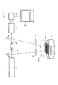
図1は、この発明の実施の形態が適用可能なレーザー誘起蛍光分析装置(Laser Induced Breakdown Spectroscopyを利用した高速の分析装置)の一例を説明する概略図である。 FIG. 1 is a schematic diagram for explaining an example of a laser-induced fluorescence analyzer (high-speed analyzer using Laser Induced Breakdown Spectroscopy) to which an embodiment of the present invention can be applied.
図13に示されるように、レーザー誘起蛍光分析装置(元素分析装置)1は、レーザー装置(光源)11、導光光学系12、照射光学系13、試料保持部14、検出光学系15、伝送光学系16、光検出器17、光電変換装置18および信号処理部19等を含む。
As shown in FIG. 13, a laser-induced fluorescence analyzer (elemental analyzer) 1 includes a laser device (light source) 11, a light guide
レーザー装置(光源)11は、所定波長のレーザー光を出射する。なお、レーザー装置11としては、例えばジャイアントパルス(GP)発振方式のNd:YAGレーザー等が利用可能である。
The laser device (light source) 11 emits laser light having a predetermined wavelength. For example, a giant pulse (GP) oscillation type Nd: YAG laser can be used as the
また、レーザー装置11は、例えばパルス幅が5nsec前後、ピークパワーが14〜20MW、伝送エネルギーが70〜100mJ(ピークパワー密度で80GW/cm2)程度のレーザー光を出力できる。なお、レーザー装置11は、多くの場合、発振制御装置、電源装置、冷却装置等を含むが、詳細な説明は省略する。
The
導光光学系12は、光源(レーザー装置)11からのレーザー光を被測定物(対象物質すなわち試料)に向けて案内する。なお、導光光学系12には、図示するようなミラーを含む光学系はもちろん、例えば光ファイバもしくはアレイ方式の導波路構造が利用可能である。
The light guide
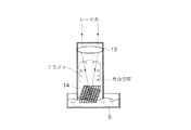
照射光学系13は、例えば所定の焦点距離を有する少なくとも1枚の凸レンズを含み、試料Sを保持した試料保持部14の所定位置に、導光光学系12により案内されるレーザー光を所定の集光状態で照射する。なお、照明光学系13の焦点位置は、以下に説明するが試料保持部14において、例えば試料Sが液体様である場合に、試料(液面または液中)Sそのものではなく、試料保持部14の所定の位置である。
The irradiation
試料保持部14は、図2に示すように、金属、例えば銅(Cu)の細い線材を編み込むことで、あるいは薄い板状体をエッチング等によりメッシュ状とした構造であり、試料Sが固体あるいは粉体である場合には直接試料を保持可能で、試料Sが液体様である場合にはその一部が試料Sと接触されることで、照明光学系13により集光されるレーザー光の焦点(集光)位置あるいはその近傍に試料S(液体様)を位置させる。
As shown in FIG. 2, the
検出光学系15は、例えば少なくとも1枚の凸レンズを含み、レーザー光が試料保持部14に照射されることで生じるプラズマ、およびそのプラズマの発生により試料から生起される蛍光である放射光を捕獲して後段の伝送光学系16に入力する。
The detection
伝送光学系16は、検出光学系15により検出された放射光を所定の方向に案内する。
The transmission optical system 16 guides the emitted light detected by the detection
光検出器17は、伝送光学系16を介して伝送された放射光を受光し、所定波長の光またはスペクトル分布を弁別(特定)する。なお、光検出器17は、例えばモノクロメータ等であって、例えばグレーティング(回折格子)や波長フィルタ等を含む周知の分光計または試料Sの特性に合わせた検出機構が任意に組み合わせられている。
The
光電変換装置18は、光検出器17により弁別された所定波長の光またはスペクトル分布を電気信号あるいは画像信号に変換する。なお、光電変換装置18は、モノクロメータ(光検出器)17により弁別された特定の波長の光(蛍光または蛍光スペクトル)を受光してその光強度に対応する電気信号を出力するもので、例えば周知のCCDカメラやフォトマルチプライヤもしくはFFTアナライザ等が、試料Sの特性に合わせて任意に選択される。
The
信号処理部19は、光電変換装置18から出力される出力信号を信号処理し、得られた蛍光またはスペクトル分布から、対象物質すなわち試料(対象物質)の種類や濃度を特定する。なお、信号処理部19は、光電変換装置18から出力される画像またはスペクトル分布等を一時的に記憶し、予め記憶されている「元素同定プログラム」や「元素定量プログラム」、もしくは光電変換装置18から供給される画像データ等に所定の処理を加えるアルゴリズム等に従って試料Sの特性を解析またはその前段階としてデータを処理する。また、光電変換装置18が、例えばFFTアナライザである場合には、表示された画面の目視によりスペクトル分布を確認することができる。
The
図1に示したレーザー誘起蛍光分析装置1においては、例えば液体様の対象物質Sは、試料保持部14の金属メッシュによる毛管現象により、液面あるいは液中から所定量だけ吸い上げられて、メッシュに適度に保持される。
In the laser-induced fluorescence analyzer 1 shown in FIG. 1, for example, a liquid-like target substance S is sucked up from a liquid surface or a predetermined amount by a capillary phenomenon due to a metal mesh of the
この状態で、レーザー装置11から出力されたパルスレーザー光が導光光学系12および照射光学系13を通じて、試料保持部14およびその金属メッシュにより液面あるいは液中から吸い上げられている状態の試料Sに照射される。
In this state, the sample S in a state in which the pulse laser beam output from the
これにより、試料Sがプラズマ化し、このプラズマエネルギーにより試料中に存在する各元素から、それそれ固有の蛍光または蛍光を含むスペクトルが放射される。また、この際、金属メッシュの材質の元素の一部から、同様に蛍光または蛍光を含むスペクトルが放射される。なお、金属メッシュは、その一部が、プラズマのエネルギーにより僅かに溶融あるいは昇華するが、試料Sが毛管現象により継続的に供給されることで、焼損したり、毛管効果が失われることはない。 As a result, the sample S is turned into plasma, and each plasma element emits a unique fluorescence or a spectrum including fluorescence from each element present in the sample. At this time, fluorescence or a spectrum including fluorescence is similarly emitted from some of the elements of the material of the metal mesh. A part of the metal mesh is slightly melted or sublimated by the energy of the plasma, but the sample S is not continuously burned or the capillary effect is not lost by the capillary phenomenon. .
この発光(蛍光を含むスペクトル)は、検出光学系15および伝送光学系16を介してモノクロメータ(光検出器)17に案内される。
The emitted light (spectrum including fluorescence) is guided to a monochromator (photodetector) 17 through the detection
以下、光検出器17で、試料Sのうちの溶媒からのスペクトル成分等が除去され、試料Sに含まれる元素に固有のスペクトルと、金属メッシュ(試料保持部14)の材質である元素に固有のスペクトルが抽出される。
Hereinafter, the spectral components and the like from the solvent in the sample S are removed by the
このようにして抽出された蛍光あるいは蛍光を含むスペクトル(スペクトル分布)は、光電変換装置18により光電変換され、変換された画像あるいはデータが信号処理部19に入力される。
The fluorescence or spectrum including the fluorescence (spectrum distribution) extracted in this way is photoelectrically converted by the
従って、試料Sに含まれる元素が特定される。例えば、Li(リチウム)を含む溶液がCu(銅)により形成された金属メッシュにより薄い膜状に保持された状態で、レーザー光を照射して得られたスペクトルは、図4に示される通り「Cu」の特徴的なスペクトル分布に加えて、「Li」のスペクトルを含んだスペクトル分布として、光電変換装置18による出力画像として出力される。比較のため、金属メッシュ(試料保持部14)のみを用いて、同一の条件で得たスペクトルを図5に示す。すなわち、図4に示したスペクトルは、明らかに金属メッシュに用いた物質である「Cu」のスペクトルと試料Sのスペクトルからなることが確認できる。
Therefore, the element contained in the sample S is specified. For example, a spectrum obtained by irradiating a laser beam in a state where a solution containing Li (lithium) is held in a thin film shape by a metal mesh formed of Cu (copper) is as shown in FIG. In addition to the characteristic spectral distribution of “Cu”, a spectral distribution including the spectrum of “Li” is output as an output image by the
なお、試料(対象物質)Sを、金属メッシュの試料保持部14による毛管現象で液膜状として液面または液中から所定量だけ吸い上げてレーザー光の集光位置に位置させたことにより、図3に示すように特に試料Sが液体様である場合に必要となる「自由空間」も、金属メッシュの隙間に液体が含侵することにより、同時に得られる。
In addition, the sample (target substance) S is formed into a liquid film by capillary action by the
従って、例えばICP発光分析のような試料の前処理や、レーザー光の集光位置に液体を霧状に供給するための補助的な装置等が不要で、しかも試料保持部14に用いる材質のための同一工程の測定(分析)も必要なく、容易に試料(溶媒)中に含まれる元素の種類や濃度を測定できる。
Therefore, for example, pretreatment of the sample such as ICP emission analysis and an auxiliary device for supplying the liquid in the form of a mist to the condensing position of the laser beam are unnecessary, and the material used for the
また、従来多くの時間と精度が必要とされた試料をレーザー光の集光点(焦点位置)に配置する工程も、金属メッシュの少なくとも一部をレーザー光の集光点に位置させるのみで、照射位置調整機構等の機構も不要で、小型で低コストの分析装置が提供される。 In addition, the process of placing a sample, which has conventionally required a lot of time and accuracy, at the laser light condensing point (focal position) also requires that at least a part of the metal mesh be positioned at the laser light condensing point. There is no need for a mechanism such as an irradiation position adjustment mechanism, and a small and low-cost analyzer is provided.
なお、金属メッシュ(試料保持部)14において、試料Sを含む液体が薄い液膜となることにより、ブレークダウンプラズマを発生させるために要求されるレーザー光の強度が僅かで済む。 In addition, in the metal mesh (sample holding part) 14, since the liquid containing the sample S becomes a thin liquid film, the intensity of the laser beam required for generating breakdown plasma is small.
なお、この発明は、前記各実施の形態に限定されるものではなく、その実施の段階ではその要旨を逸脱しない範囲で種々な変形もしくは変更が可能である。また、各実施の形態は、可能な限り適宜組み合わせて実施されてもよく、その場合、組み合わせによる効果が得られる。 The present invention is not limited to the above-described embodiments, and various modifications or changes can be made without departing from the scope of the invention when it is implemented. Moreover, each embodiment may be implemented in combination as appropriate as possible, and in that case, the effect of the combination can be obtained.
1…レーザー誘起蛍光分析装置、11…レーザー装置(光源)、12…導光光学系、13…照射光学系、14…試料保持部(金属メッシュ)、15…検出光学系、16…伝送光学系、17…光検出器、18…光電変換装置、19…信号処理部。 DESCRIPTION OF SYMBOLS 1 ... Laser induced fluorescence analyzer, 11 ... Laser apparatus (light source), 12 ... Light guide optical system, 13 ... Irradiation optical system, 14 ... Sample holding part (metal mesh), 15 ... Detection optical system, 16 ... Transmission optical system , 17 ... photodetector, 18 ... photoelectric conversion device, 19 ... signal processing unit.
Claims (9)
この光源からの光を被測定物に案内する導光光学系と、
この導光光学系により案内された光を被測定物に照射する照射光学系と、
この照射光学系の焦点位置およびその近傍に位置され、被測定物を保持する試料保持部と、
この試料保持部において前記照射光学系により集光される光により生じるプラズマおよび被測定物に固有の蛍光または蛍光スペクトルを捕獲する検出光学系と、
を有することを特徴とする分析装置。 A light source that emits laser light;
A light guide optical system for guiding light from this light source to the object to be measured;
An irradiation optical system for irradiating the object to be measured with the light guided by the light guide optical system;
A sample holder for holding the object to be measured, located at and near the focal position of the irradiation optical system;
A detection optical system that captures the fluorescence or the fluorescence spectrum inherent to the plasma and the object to be measured generated by the light collected by the irradiation optical system in the sample holder;
An analysis apparatus comprising:
この光源からの光を被測定物に案内する導光光学系と、
この導光光学系により案内された光を被測定物に照射する照射光学系と、
この照射光学系の焦点位置およびその近傍に位置され、被測定物を保持する試料保持部と、
この試料保持部において前記照射光学系により集光される光により生じるプラズマおよび被測定物に固有の蛍光または蛍光スペクトルを捕獲する検出光学系と、
この検出光学系により捕獲された被測定物に固有の蛍光または蛍光スペクトルを分光器または信号処理装置もしくは光電変換装置に案内する伝送光学系と、
を有することを特徴とする分析装置。 A light source that emits laser light;
A light guide optical system for guiding light from this light source to the object to be measured;
An irradiation optical system for irradiating the object to be measured with the light guided by the light guide optical system;
A sample holder for holding the object to be measured, located at and near the focal position of the irradiation optical system;
A detection optical system that captures the fluorescence or the fluorescence spectrum inherent to the plasma and the object to be measured generated by the light collected by the irradiation optical system in the sample holder;
A transmission optical system for guiding the fluorescence or fluorescence spectrum inherent to the measurement object captured by the detection optical system to a spectroscope or a signal processing device or a photoelectric conversion device;
An analysis apparatus comprising:
Priority Applications (1)
| Application Number | Priority Date | Filing Date | Title |
|---|---|---|---|
| JP2004029417A JP2005221373A (en) | 2004-02-05 | 2004-02-05 | Element analyzer |
Applications Claiming Priority (1)
| Application Number | Priority Date | Filing Date | Title |
|---|---|---|---|
| JP2004029417A JP2005221373A (en) | 2004-02-05 | 2004-02-05 | Element analyzer |
Publications (2)
| Publication Number | Publication Date |
|---|---|
| JP2005221373A true JP2005221373A (en) | 2005-08-18 |
| JP2005221373A5 JP2005221373A5 (en) | 2007-03-22 |
Family
ID=34997127
Family Applications (1)
| Application Number | Title | Priority Date | Filing Date |
|---|---|---|---|
| JP2004029417A Pending JP2005221373A (en) | 2004-02-05 | 2004-02-05 | Element analyzer |
Country Status (1)
| Country | Link |
|---|---|
| JP (1) | JP2005221373A (en) |
Cited By (6)
| Publication number | Priority date | Publication date | Assignee | Title |
|---|---|---|---|---|
| JP2007003510A (en) * | 2005-05-26 | 2007-01-11 | Toshiba Corp | Element analysis method and apparatus, and analysis sample producing method |
| JP5605372B2 (en) * | 2009-12-09 | 2014-10-15 | 株式会社村田製作所 | Spectroscopic measurement device holding gap arrangement structure, frame member used therefor, and spectroscope |
| CN104181131A (en) * | 2014-08-15 | 2014-12-03 | 中国科学院上海技术物理研究所 | Automatic positioning and calibrating device for infrared modulation photoluminescence (PL) bi-dimensional imaging light path |
| KR20160065033A (en) * | 2014-11-28 | 2016-06-08 | 광주과학기술원 | Device and method for elemental ananlysis of pollutants in liquids |
| WO2016085313A3 (en) * | 2014-11-28 | 2016-07-21 | 광주과학기술원 | Chemical element analysis device and method for contaminants in liquid |
| CN117222090A (en) * | 2023-07-18 | 2023-12-12 | 中国人民解放军国防科技大学 | Planar plasma velocity measurement system and method capable of adjusting high spatial resolution |
-
2004
- 2004-02-05 JP JP2004029417A patent/JP2005221373A/en active Pending
Cited By (10)
| Publication number | Priority date | Publication date | Assignee | Title |
|---|---|---|---|---|
| JP2007003510A (en) * | 2005-05-26 | 2007-01-11 | Toshiba Corp | Element analysis method and apparatus, and analysis sample producing method |
| JP5605372B2 (en) * | 2009-12-09 | 2014-10-15 | 株式会社村田製作所 | Spectroscopic measurement device holding gap arrangement structure, frame member used therefor, and spectroscope |
| CN104181131A (en) * | 2014-08-15 | 2014-12-03 | 中国科学院上海技术物理研究所 | Automatic positioning and calibrating device for infrared modulation photoluminescence (PL) bi-dimensional imaging light path |
| KR20160065033A (en) * | 2014-11-28 | 2016-06-08 | 광주과학기술원 | Device and method for elemental ananlysis of pollutants in liquids |
| WO2016085313A3 (en) * | 2014-11-28 | 2016-07-21 | 광주과학기술원 | Chemical element analysis device and method for contaminants in liquid |
| KR101723535B1 (en) * | 2014-11-28 | 2017-04-06 | 광주과학기술원 | Device and method for elemental ananlysis of pollutants in liquids |
| CN107075944A (en) * | 2014-11-28 | 2017-08-18 | 光州科学技术院 | The analysis of chemical elements device and analysis method of polluter in liquid |
| US20170322162A1 (en) * | 2014-11-28 | 2017-11-09 | Gwangju Institute Of Science And Technology | Chemical element analysis device and method for contaminants in liquid |
| US10175173B2 (en) | 2014-11-28 | 2019-01-08 | Gwangju Institute Of Science And Technology | Chemical element analysis device and method for contaminants in liquid |
| CN117222090A (en) * | 2023-07-18 | 2023-12-12 | 中国人民解放军国防科技大学 | Planar plasma velocity measurement system and method capable of adjusting high spatial resolution |
Similar Documents
| Publication | Publication Date | Title |
|---|---|---|
| JP4417932B2 (en) | Laser beam incidence optical device for optical fiber | |
| US7251022B2 (en) | Dual fiber microprobe for mapping elemental distributions in biological cells | |
| CN110088600B (en) | Laser-induced breakdown spectroscopy system and method, and detection system and method thereof | |
| US8675193B2 (en) | Near-field material processing system | |
| Ciucci et al. | CF-LIPS: a new approach to LIPS spectra analysis | |
| JP2010038560A (en) | Element analyzer and element analysis method | |
| JP2009288068A (en) | Analyzing method and analyzer | |
| JP2005221373A (en) | Element analyzer | |
| JP2005140529A (en) | Apparatus and method for analyzing element | |
| JP2010190595A (en) | Laser spectroscopic analyzer, and laser spectroscopic analyzing method using the same | |
| JP2000310596A (en) | Element analyzer | |
| JP2005201762A (en) | Lithium leak detector and lithium leak detection method | |
| JP2009288067A (en) | Analyzing method and analyzer | |
| JP5117966B2 (en) | Sample analyzer | |
| KR102141601B1 (en) | All in one optical device | |
| JP2005242292A (en) | Laser beam incident optical device | |
| JP2010197229A (en) | Fluorescent x-ray analyzer | |
| RU2303255C1 (en) | Laser atomic emissive spectrometer "laes" | |
| JP2602523B2 (en) | Cathodoluminescence measuring device | |
| JP2006300808A (en) | Raman spectrometry system | |
| WO2015190617A1 (en) | Analysis method and analysis device | |
| JP2010216915A (en) | Method and device for continuously monitoring molten steel | |
| JP5436319B2 (en) | Spectroscopic measuring method, spectroscopic measuring device | |
| JP2006275621A (en) | Analyzer | |
| JP2002526767A (en) | Method and system for isotope-selective measurement of chemical elements present in substances |
Legal Events
| Date | Code | Title | Description |
|---|---|---|---|
| A521 | Written amendment |
Free format text: JAPANESE INTERMEDIATE CODE: A523 Effective date: 20070205 |
|
| A621 | Written request for application examination |
Free format text: JAPANESE INTERMEDIATE CODE: A621 Effective date: 20070205 |
|
| A977 | Report on retrieval |
Effective date: 20090128 Free format text: JAPANESE INTERMEDIATE CODE: A971007 |
|
| A131 | Notification of reasons for refusal |
Free format text: JAPANESE INTERMEDIATE CODE: A131 Effective date: 20090602 |
|
| A02 | Decision of refusal |
Effective date: 20091013 Free format text: JAPANESE INTERMEDIATE CODE: A02 |