JP2005219814A - Dropper body - Google Patents
Dropper body Download PDFInfo
- Publication number
- JP2005219814A JP2005219814A JP2005027390A JP2005027390A JP2005219814A JP 2005219814 A JP2005219814 A JP 2005219814A JP 2005027390 A JP2005027390 A JP 2005027390A JP 2005027390 A JP2005027390 A JP 2005027390A JP 2005219814 A JP2005219814 A JP 2005219814A
- Authority
- JP
- Japan
- Prior art keywords
- dropper
- mouth
- container body
- protrusion
- cap
- Prior art date
- Legal status (The legal status is an assumption and is not a legal conclusion. Google has not performed a legal analysis and makes no representation as to the accuracy of the status listed.)
- Pending
Links
Images


Classifications
-
- B—PERFORMING OPERATIONS; TRANSPORTING
- B65—CONVEYING; PACKING; STORING; HANDLING THIN OR FILAMENTARY MATERIAL
- B65D—CONTAINERS FOR STORAGE OR TRANSPORT OF ARTICLES OR MATERIALS, e.g. BAGS, BARRELS, BOTTLES, BOXES, CANS, CARTONS, CRATES, DRUMS, JARS, TANKS, HOPPERS, FORWARDING CONTAINERS; ACCESSORIES, CLOSURES, OR FITTINGS THEREFOR; PACKAGING ELEMENTS; PACKAGES
- B65D47/00—Closures with filling and discharging, or with discharging, devices
- B65D47/04—Closures with discharging devices other than pumps
- B65D47/06—Closures with discharging devices other than pumps with pouring spouts or tubes; with discharge nozzles or passages
- B65D47/18—Closures with discharging devices other than pumps with pouring spouts or tubes; with discharge nozzles or passages for discharging drops; Droppers
Abstract
Description
本発明は、点滴ボトル、特にこのような点滴ボトルのための点滴器本体に関するものである。 The present invention relates to an infusion bottle, in particular to an infusion body for such an infusion bottle.
既に知られているように、多くの種類の液体が、点滴ボトルを用いて投与又は投薬される。薬学及びそれに類似する分野においては、特に、口用又は局所用、例えば鼻、眼若しくは耳用の医薬を正確に投与するために、液滴の形態で医薬の投与を行うことが極めて広く行われている。芳香剤などの製品についても、液滴の形態で適量に分配することが極めて一般的に行われていることである。 As already known, many types of liquids are administered or dispensed using infusion bottles. In the field of pharmacy and similar fields, it is very widespread to administer drugs in the form of droplets, in particular for the precise administration of drugs for mouth or topical use, for example nasal, ocular or otic. ing. It is very common for products such as fragrances to be dispensed in appropriate amounts in the form of droplets.
既知の点滴ボトルは、流体容器本体と、ステムと、カラーと、キャップとを有する。容器本体は、一般に閉鎖した底部と、開口した頂部とを有するほぼ円筒状の形状にする。容器本体は、通常、ガラス、ポリエチレンテレフタレートなどから形成する。 Known infusion bottles have a fluid container body, a stem, a collar, and a cap. The container body is generally cylindrical in shape with a closed bottom and an open top. The container body is usually made of glass, polyethylene terephthalate, or the like.
点滴器本体又はステムは、液滴出口のオリフィスで終端する細長い形状の頂部と、容器本体の口部の頂部に休止する底部とを有する。ステムは、カラーにより所定位置に保持し、カラーは、容器本体の口部の外側底部エッジと掛合し外側にねじ止め部を有する。 The dropper body or stem has an elongated top that terminates at the orifice of the drop outlet and a bottom resting on the top of the mouth of the container body. The stem is held in place by the collar, and the collar engages with the outer bottom edge of the mouth of the container body and has a screwed portion on the outside.
点滴ボトルを使用しない場合、特に販売前に点滴ボトルを封止しておく場合には、ステム/カラー組立体上に封止キャップを装着する。キャップの頂部内側に細長い突出部を設け、これがステムのオリフィス内に突出してこれを閉鎖するようにする。一般的には、ステムのカラーとキャップとの間にねじ部を設ける。言い換えれば、キャップを取り外せるようにキャップはカラーからねじ取れるようにする必要がある。最後に、容器ボトル内に含まれている製品に手が加えられることを防止するため、キャップの底部にロック用リング(「保証シール(seal of gurantee)」)を設けるが、このロック用リングは、使用者が点滴ボトルを最初に開封するときに破り取れるようにする必要がある。 When the infusion bottle is not used, particularly when the infusion bottle is sealed before sale, a sealing cap is mounted on the stem / collar assembly. An elongated protrusion is provided inside the top of the cap that projects into the orifice of the stem and closes it. Generally, a thread portion is provided between the collar of the stem and the cap. In other words, the cap needs to be able to be unscrewed from the collar so that the cap can be removed. Finally, a lock ring (“seal of gurantee”) is provided at the bottom of the cap to prevent the product contained in the container bottle from being tampered with. , The user needs to be able to tear it when opening the infusion bottle for the first time.
上述した種類の点滴ボトルは、極めて簡単に製造し組立てることができる考えられている。しかし、発明者は、このような点滴ボトルには多数の問題があり既知の点滴ボトルを改善する必要があることに気づいた。 It is contemplated that an infusion bottle of the type described above can be manufactured and assembled very easily. However, the inventor has realized that there are a number of problems with such infusion bottles and there is a need to improve the known infusion bottles.
第一に、本発明者は、ステム及び容器本体間の封止性、容器本体及びカラー間の封止性、並びにカラー及びステム間の封止性に関して好ましくないまた容認できない問題があることを発見した。これらの問題の主たる原因は、容器本体の口部とステムの底部との間の密着性が不完全であることと考えられる。 First, the inventor has discovered that there are unfavorable and unacceptable problems with respect to the seal between the stem and the container body, the seal between the container body and the collar, and the seal between the collar and the stem. did. The main cause of these problems is considered to be incomplete adhesion between the mouth of the container body and the bottom of the stem.
第二に、本発明者は、多くの場合に、ステムのカラーが容器本体に対して充分緊密にロックされず回転してしまうために、ステムのカラーからキャップをねじ取るのが困難であることに気づいた。 Second, the inventor often finds it difficult to screw the cap from the stem collar because the stem collar often rotates without being locked tightly against the container body. I noticed.
第三に、本発明者は、多くの場合に、キャップがカラーに対して回転してしまう、つまり容器本体に対して充分にロックされていないため、キャップに固着されている封止リングを破り取るのが困難であることを発見した。 Third, the inventor often breaks the sealing ring secured to the cap because the cap rotates relative to the collar, i.e., it is not fully locked to the container body. I found it difficult to take.
本発明の目的は、上述した問題を解決する点滴ボトルであって、実質的に漏出がなく、特に最初に使用する際に容易に開封しうる点滴ボトルを提供するにある。 It is an object of the present invention to provide an infusion bottle that solves the above-mentioned problems and that is substantially free of leakage and that can be easily opened, especially when first used.
この目的は、他の課題と共に、特許請求の範囲の請求項1に記載した改良した点滴ボトル用の点滴器本体により達成される。本発明の他の有利な特徴は、従属項に記載されている。全ての請求項は、本発明の説明と一体の部分をなすものと理解されたい。 This object is achieved, together with other problems, by an improved dropper body for an infusion bottle as claimed in claim 1. Other advantageous features of the invention are set out in the dependent claims. It is to be understood that all claims are an integral part of the description of the invention.
この目的を解決するため本発明は、容器本体に結合し、キャップにより封止することができる点滴ボトル用の点滴器本体であって、この点滴器本体は、第1液滴供給端部及び開口底部を有し、この点滴器本体の開口底部が、容器本体の口部の内側面に掛合しうる第1突出部と、容器本体の口部の外側面に掛合しうる第2突出部と、容器本体の口部の上面に掛合しうる座面とを有している点滴器本体において、容器本体の口部が実質的にペニシリン型口部であり、第2突出部が、容器本体の口部の外側面にある連続した底部エッジに掛合しうる実質的に連続した隆起部を有しており、点滴器本体が、さらに、容器本体の口部の上面に形成した対応する少なくとも1個の隆起部と協働する、座面に形成した少なくとも1個のキャビティか、又は容器本体の口部の上面に形成した対応する少なくとも1個のキャビティと協働する、座面から突出した少なくとも1個の隆起部かを有することを特徴とする。 In order to solve this object, the present invention provides an infusion bottle body for an infusion bottle that can be coupled to a container body and sealed with a cap, the infusion body comprising a first droplet supply end and an opening. A first protrusion that has a bottom, the opening bottom of the dropper body can be engaged with the inner surface of the mouth of the container body, and a second protrusion that can be engaged with the outer surface of the mouth of the container body; In the dropper main body having a seating surface that can be engaged with the upper surface of the mouth of the container main body, the mouth of the container main body is substantially a penicillin type mouth, and the second protrusion is the mouth of the container main body. The dropper body further includes a corresponding at least one correspondingly formed on the top surface of the mouth of the container body. At least one cavity formed in the seating surface or cooperating with the ridge Cooperates with at least one cavity corresponding formed on the upper surface of the mouth portion of the body, and having or at least one raised portion which protrudes from the seat surface.
第1突出部を、座面から少なくとも約1.5mm突出させるのが好ましい。第1突出部を、座面から少なくとも約2.5mm突出させるのがより好ましい。 The first protrusion is preferably protruded from the seat surface by at least about 1.5 mm. More preferably, the first protrusion protrudes from the seat surface by at least about 2.5 mm.
本発明による点滴器本体は、薬局方により許可されているポリエチレンにより形成するのが好ましい。 The dropper body according to the present invention is preferably formed from polyethylene which is permitted by the pharmacopoeia.
本発明の他の観点によれば、前述した点滴器本体と、キャップと、容器本体とを有する点滴ボトルであって、容器本体がペニシリン型口部を有し、このペニシリン型口部が、外側面と、内側面と、少なくとも1個の隆起部又はキャビティを形成した上面とを有し、キャップが、さらに、ロック用リングを有し、キャップと点滴器本体とが相対回転することを防止する装置を具える点滴ボトルを得る。 According to another aspect of the present invention, there is provided an infusion bottle having the above-described infusion device main body, a cap, and a container main body, the container main body having a penicillin-type mouth, and the penicillin-type mouth is The cap has a side surface, an inner surface, and an upper surface forming at least one ridge or cavity, and the cap further has a locking ring to prevent relative rotation between the cap and the dropper body. Get an infusion bottle with the device.
キャップと点滴器本体とが相対回転することを防止する装置が、少なくとも一個の隆起部と、対応する少なくとも1個のキャビティとを有するのが好ましい。 Preferably, the device for preventing relative rotation of the cap and the dropper body has at least one ridge and at least one corresponding cavity.
前記少なくとも一個の隆起部を底部リングの内面に形成し、前記対応する少なくとも1個のキャビティを外側の第2突出部に形成するのが好ましい。 Preferably, the at least one raised portion is formed on the inner surface of the bottom ring, and the corresponding at least one cavity is formed on the outer second protrusion.
好適例によれば、点滴器本体がねじ部を有し、キャップがこれに対応するねじ部を有し、これらを互いにねじ連結するようにする。 According to a preferred embodiment, the dropper body has a threaded portion and the cap has a corresponding threaded portion, which are screwed together.
代表的には、点滴ボトルは、口、鼻、眼若しくは耳用の医薬を含む用途に利用する。また、芳香剤などにも使用することができる。 Typically, infusion bottles are used for applications involving medications for the mouth, nose, eyes or ears. It can also be used as a fragrance.
本発明を、以下に記載する種々の図面を参照した実施例により詳細に説明して明らかなものとする。実施例は本発明を限定するものではない。 The invention will become apparent from the following detailed description of embodiments with reference to the various drawings described below. The examples do not limit the invention.
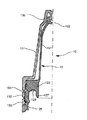
上述したように、既知の点滴ボトル1(図1参照)は、流体を入れる容器本体2と、ステム3と、カラー4と、キャップ5とを有する。容器本体2は、一般にほぼ円筒形の形状であり、閉じた底部と、頂部における開口した口部21とを有する。
As described above, the known infusion bottle 1 (see FIG. 1) has a
ステム3は、細長い形状の頂部31を有し、この頂部31は、液滴の出口であるオリフィス32と底部33とで終端しており、この底部33は、容器本体2の口部21の頂部に休止する。ステム3をカラー4により所定の位置に保持し、カラー4は、容器本体2の口部21の外側底部エッジと掛合させ、且つ雄ねじ部を形成する。
The stem 3 has an elongated top portion 31, which terminates at an
点滴ボトルを使用しないとき、特に販売前の封止した状態にでは、ステム/カラー組立体上に封止キャップ5を装着する。封止キャップ5の頂部内側には、細長い突出部51を設け、この突出部をステム3のオリフィス32内に貫入してこれを封止する。通常は、ステム3のカラー4と、キャップ5との間にねじ部を設ける。つまり、キャップ5を取り外せるようにカラー4からキャップ5をねじ取れるようにする必要がある。最後に、容器ボトル内に含まれている製品に手が加えられることを防止するため、キャップ5の底部にロック用リング52(「保証シール(seal of gurantee)」)を設けるが、このロック用リング52は使用者が点滴ボトル1を最初に開封する際に破り取れるようにする必要がある。
When the infusion bottle is not used, the sealing cap 5 is mounted on the stem / collar assembly, particularly in a sealed state before sale. An
本発明によれば、図2乃至7を参照して説明するように、ステム及びカラーを単一ピースとして形成し、以下の説明ではこれを「点滴器本体」と称する。従って、本発明による点滴ボトル10は、容器本体11と、点滴器本体12と、キャップ13とを有する。この点滴器本体12は、細長い部分121を有し、この細長い部分121は、一方の端部にオリフィス122を、その反対側の他方の端部に底部123を設ける。
In accordance with the present invention, the stem and collar are formed as a single piece, as will be described with reference to FIGS. 2-7, and in the following description this will be referred to as the “dropper body”. Accordingly, the
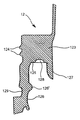
図4,5及び6に明確に示すように、点滴器本体12の底部123に雄ねじ部124を設け、この底部123にはキャップ13のねじ部137がねじ付けられるようにする。この底部123は、座面125と、内側の第1突出部127と、外側の第2突出部126とを有する。この座面125は、容器本体11の口部111の上面112に休止させることができる。外側の第2突出部126は、容器本体11の口部111の外側面113に掛合させることができる。詳細には、外側の第2突出部126の座面125から離れた位置に、丸い連続した隆起部126′を設ける。このような隆起部126′は、容器本体11の口部111の外側面113にある底部エッジ113′に掛合するよう設計する。これら隆起部126′及び底部エッジ113′が協働するため、点滴器本体12及び容器本体11が共に組立てられているときに、ユーザは点滴器本体12を解離するおそれがない。
As clearly shown in FIGS. 4, 5, and 6, a male threaded
内側の第1突出部127は、容器本体11の口部111の内側面114に掛合することができる。換言すると、座面125と、外側の第2突出部126と、内側の第1突出部127とが、容器本体11の口部111上に嵌合しうる環状キャビティを規定する。本発明による点滴ボトル10の容器本体11における口部111の種類は、一般に知られている「ペニシリン型」にするのが有利である。
The inner first projecting
第1突出部127及び第2突出部126は、ほぼ円形の突出部にするのが好ましい。これら内側の第1突出部127及び外側の第2突出部126は、ほぼ円形で連続した突出部にするのがさらに好ましい。
The
第1(内側)突出部127は、座面125から少なくとも約1.5mm突出させるのが好ましい。第1(内側)突出部127は、少なくとも約2.5mm突出させるのがさらに好ましい。
The first (inner)
点滴器本体は、薬局方により許可されているポリエチレンであって、利用に適した弾性及び硬度特性を有するものから形成するのが好ましい。 The dropper body is preferably made of polyethylene approved by the pharmacopoeia and having elastic and hardness properties suitable for use.
本発明によれば、内側の第1突出部127と、外側の第2突出部126と、座面125とにより形成した環状キャビティは、使用した材料の弾性と相俟って、流体の損失又は漏出に対する効果的な封止部になる(図3)。本発明によれば、容器本体の口部が精密に製造されていない場合であっても、封止が確実になされるため有利である。
According to the present invention, the annular cavity formed by the inner
本発明の第1の好適例によれば、点滴器本体12の座面125に少なくとも1個のキャビティ128を設け、このキャビティ128を、容器本体11の口部111の上面112にある対応する隆起部115と協働させる。複数のキャビティ128及び複数の対応する隆起部115を設けてある種のかみ合わせ部を形成するのが好ましい。
According to a first preferred embodiment of the present invention, at least one
本発明の第2の実施例(図示せず)によれば、点滴器本体12の座面125に少なくとも1個の隆起部を設け、この隆起部を、容器本体11の口部111の上面112にある対応する少なくとも1個のキャビティと協働させる。複数のキャビティ及び複数の対応する隆起部を設けてある種のかみ合わせ部を形成し、点滴器本体12と容器本体11とが相対回転するのを防止しうるようにするのが好ましい。
According to the second embodiment (not shown) of the present invention, at least one raised portion is provided on the
本発明の第3の実施例(図示せず)によれば、容器本体11の口部111の外側面113に少なくとも1個の隆起部を設け、この隆起部を外側の第2突出部126上の対応する少なくとも1個のキャビティと協働させる。複数のキャビティ及び複数の対応する隆起部を設けてある種のかみ合わせ部を形成し、点滴器本体12と容器本体11とが相対回転するのを防止するのが好ましい。
According to the third embodiment (not shown) of the present invention, at least one raised portion is provided on the
本発明の第4の実施例(図示せず)によれば、容器本体11の口部111の外側面113に少なくとも1個のキャビティを設け、このキャビティを外側の第2突出部126上の対応する少なくとも1個の隆起部と協働させる。複数のキャビティ及び複数の対応する隆起部を設けてある種のかみ合わせ部を形成し、点滴器本体12と容器本体11とが相対回転するのを防止するのが好ましい。
According to the fourth embodiment (not shown) of the present invention, at least one cavity is provided on the
キャビティ及び隆起部からなるこれらの手段によれば、点滴器本体12は容器本体11に対して相対回転できず、かつキャップ13は容易にねじ付けたり又はねじ戻したりすることができるようになる。
With these means consisting of a cavity and a ridge, the
キャップ13の開口端部131近傍にロック用リング(「保証シール(seal of gurantee)」)132を設けるが、このロック用リング132は、点滴ボトル10を最初に開封する際に破り取れるようにしておく必要がある。このロック用リング132は、底部リング133及びキャップの残りの部分に、脆弱化したラインを形成する若干数のポイント134で連結する。
A locking ring (“seal of gurantee”) 132 is provided near the
本発明の他の観点によれば、点滴器本体12とキャップ13とが相対回転するのを防止するかみ合わせ部を底部リング133の領域に設ける。本発明によれば、点滴器本体12の外側の第2突出部126の底部にキャビティ129を形成し、キャップ13の底部リング133の内側に対応する隆起部135を形成する。これらによるかみ合わせ部が点滴器本体12とキャップ13との相対回転を防止するため、ロック用リング132を破り取る際にキャップ13の頂部136が回転できず、ロック用リング132の取外しに有利である。
According to another aspect of the present invention, a meshing portion is provided in the region of the
本発明は、特許請求の範囲により定められる保護範囲から逸脱することなく、多数の変更、付加及び変形を加えうるものであり、またその一部を同等の機能を有する他の部品に置き換えうるものである。 The present invention can be subjected to numerous modifications, additions and modifications without departing from the scope of protection defined by the claims, and a part thereof can be replaced with other parts having equivalent functions. It is.
10 点滴ボトル
11 容器本体
12 点滴器本体
13 キャップ
111 口部
121 細長い部分
122 オリフィス
123 底部
124 雄ねじ部
126 第2突出部
127 第1突出部
128 キャビティ
132 ロック用リング
136 頂部
133 底部リング
DESCRIPTION OF
Claims (9)
前記容器本体(11)の口部(111)の内側面(114)に掛合しうる第1突出部(127)と、
前記容器本体(11)の口部(111)の外側面(113)に掛合しうる第2突出部(126)と、
前記容器本体(11)の口部(111)の上面(112)に掛合しうる座面(125)と
を有している点滴器本体(12)において、
前記容器本体(11)の前記口部(111)がペニシリン型口部(111)であり、
前記第2突出部(126)が、前記容器本体(11)の前記口部(111)の前記外側面(113)にある連続した底部エッジ(113′)に掛合しうるほぼ連続した隆起部(126′)を有しており、
前記点滴器本体(12)が、さらに、
前記容器本体(11)の前記口部(111)の前記上面(112)上に形成した対応する少なくとも1個の隆起部(115)と協働する、前記座面(125)に形成した少なくとも1個のキャビティ(128)か、又は
前記容器本体(11)の前記口部(111)の前記上面(112)上に形成した対応する少なくとも1個のキャビティと協働する、前記座面(125)から突出した少なくとも1個の隆起部か
を有することを特徴とする点滴器本体(12)。 An infusion body (12) for an infusion bottle (10) that is coupled to a container body (11) and can be sealed by a cap (13), the infusion body (12) being a first droplet It has a supply end (122) and an open bottom (123), and the open bottom (123) of this dropper body is
A first protrusion (127) capable of engaging with an inner surface (114) of the mouth (111) of the container body (11);
A second protrusion (126) capable of engaging with the outer surface (113) of the mouth (111) of the container body (11);
In the dropper body (12) having a seating surface (125) that can be engaged with the upper surface (112) of the mouth (111) of the container body (11),
The mouth part (111) of the container body (11) is a penicillin type mouth part (111),
A substantially continuous ridge (126) in which the second protrusion (126) can engage a continuous bottom edge (113 ') on the outer surface (113) of the mouth (111) of the container body (11). 126 ′),
The dropper body (12) further comprises:
At least one formed on the seating surface (125) cooperating with a corresponding at least one raised portion (115) formed on the upper surface (112) of the mouth (111) of the container body (11). Said cavity (128) or said seating surface (125) cooperating with at least one corresponding cavity formed on said upper surface (112) of said mouth (111) of said container body (11) A dropper body (12) characterized in that it has at least one ridge projecting from the dropper body (12).
前記容器本体(11)が、ペニシリン型口部(111)を有し、このペニシリン型口部が、外側面(113)と、内側面(114)と、少なくとも1個の隆起部(115)又はキャビティを形成した上面(112)とを有し、
前記キャップ(13)が、さらに、前記キャップ(13)と前記点滴器本体(12)とが相対回転することを防止する装置(135,129)に関連するロック用リング(132)を具える
ことを特徴とする点滴ボトル(10)。 In an infusion bottle (10) comprising the inflator body (12) according to any one of claims 1 to 4, a cap (13), and a container body (11),
The container body (11) has a penicillin type mouth portion (111), and the penicillin type mouth portion has an outer side surface (113), an inner side surface (114), and at least one raised portion (115) or And an upper surface (112) having a cavity formed therein,
The cap (13) further comprises a locking ring (132) associated with a device (135, 129) that prevents relative rotation between the cap (13) and the dropper body (12). An infusion bottle (10) characterized by
Applications Claiming Priority (1)
| Application Number | Priority Date | Filing Date | Title |
|---|---|---|---|
| EP04075346A EP1561698B1 (en) | 2004-02-05 | 2004-02-05 | Dropper bottle |
Publications (1)
| Publication Number | Publication Date |
|---|---|
| JP2005219814A true JP2005219814A (en) | 2005-08-18 |
Family
ID=34673711
Family Applications (1)
| Application Number | Title | Priority Date | Filing Date |
|---|---|---|---|
| JP2005027390A Pending JP2005219814A (en) | 2004-02-05 | 2005-02-03 | Dropper body |
Country Status (8)
| Country | Link |
|---|---|
| US (1) | US7175057B2 (en) |
| EP (1) | EP1561698B1 (en) |
| JP (1) | JP2005219814A (en) |
| AT (1) | ATE461872T1 (en) |
| CA (1) | CA2495971C (en) |
| DE (1) | DE602004026155D1 (en) |
| ES (1) | ES2340384T3 (en) |
| HK (1) | HK1077793A1 (en) |
Cited By (1)
| Publication number | Priority date | Publication date | Assignee | Title |
|---|---|---|---|---|
| JP2008137694A (en) * | 2006-11-30 | 2008-06-19 | Yoshino Kogyosho Co Ltd | Cap fitting structure of container |
Families Citing this family (16)
| Publication number | Priority date | Publication date | Assignee | Title |
|---|---|---|---|---|
| EP1838580A1 (en) * | 2005-01-13 | 2007-10-03 | Bormioli Rocco & Figlio S.p.A. | A process for sterile packaging of containers with drop-dispensers, and means for actuating the process |
| JP4987661B2 (en) * | 2007-10-19 | 2012-07-25 | 東洋製罐株式会社 | Extraction material |
| FR2929249B1 (en) | 2008-03-27 | 2012-02-17 | Rexam Pharma La Verpilliere | DEVICE FOR DISPENSING LIQUID CONTAINED IN A RESERVOIR |
| US20100022916A1 (en) | 2008-07-24 | 2010-01-28 | Javanbakhsh Esfandiari | Method and Apparatus for Collecting and Preparing Biological Samples for Testing |
| WO2010123164A1 (en) * | 2009-04-22 | 2010-10-28 | 주식회사 한국알테코 | Method for manufacturing adhesive containers and adhesive containing products |
| FR3031343B1 (en) * | 2015-01-06 | 2017-07-28 | Oreal | DEVICE FOR CONDITIONING AND DISPENSING A PRODUCT, AND ASSOCIATED DELIVERY METHOD |
| DE102015102273B3 (en) * | 2015-02-18 | 2016-03-10 | Louvrette Gmbh Design & Packaging | dropper |
| US9650188B1 (en) | 2016-04-14 | 2017-05-16 | Healthstar, Inc. | Delayed pierce, sealed container |
| ES2887000T3 (en) * | 2016-11-28 | 2021-12-21 | Oreal | Device for packaging and dispensing a product comprising a mobile piston |
| KR20240014592A (en) * | 2017-12-27 | 2024-02-01 | 생-고뱅 퍼포먼스 플라스틱스 코포레이션 | Cap assembly |
| JP2021512023A (en) * | 2018-01-24 | 2021-05-13 | ナノドロッパー, インコーポレイテッド | Assembly and method for delivering small volumes of droplets from squeeze bottles |
| US11203467B2 (en) | 2018-01-24 | 2021-12-21 | Nanodropper, Inc. | Assembly and method for delivery of micro-volume droplets from a squeeze bottle |
| US10723526B1 (en) | 2019-03-29 | 2020-07-28 | Chubby Gorilla, Inc. | Bottle and cap arrangement |
| US20210155382A1 (en) * | 2019-11-26 | 2021-05-27 | Eternal Ink, LLC | Tamper Evident Container |
| WO2023138753A1 (en) * | 2022-01-18 | 2023-07-27 | Aptar Radolfzell Gmbh | Liquid dispenser |
| US11931749B2 (en) * | 2022-08-03 | 2024-03-19 | Gerresheimer Boleslawiec Spolka Akcyjna | Dispenser for dispensing liquids |
Citations (4)
| Publication number | Priority date | Publication date | Assignee | Title |
|---|---|---|---|---|
| JPS5957359U (en) * | 1982-10-06 | 1984-04-14 | 三笠産業株式会社 | bottle lid |
| JPS6369578U (en) * | 1986-06-19 | 1988-05-10 | ||
| JPH04215962A (en) * | 1989-12-15 | 1992-08-06 | Cebal | Sealing container, screw type cap for sealing to be used for said sealing container, and manufacture therefor |
| JPH10297656A (en) * | 1997-04-25 | 1998-11-10 | Yoshino Kogyosho Co Ltd | Cap structure for container |
Family Cites Families (8)
| Publication number | Priority date | Publication date | Assignee | Title |
|---|---|---|---|---|
| US455916A (en) * | 1891-07-14 | Cash-register | ||
| GB839285A (en) * | 1957-08-27 | 1960-06-29 | Malpas Charles H | Improved caps or nozzles for bottles, jars and like containers |
| FR1266243A (en) * | 1960-08-29 | 1961-07-07 | Two-part stopper, nozzle, sprayer and dropper for bottles and similar containers | |
| FR2600629B1 (en) * | 1986-06-24 | 1989-03-17 | Astra Plastique | TAMPER-FREE CLOSURE MEANS FOR A THREADED NECK CONTAINER |
| IT207994Z2 (en) * | 1986-07-31 | 1988-03-14 | Capsulit Spa | CLOSURE FOR BOTTLES OR SIMILAR, EQUIPPED WITH DROPPER. |
| DE9300042U1 (en) * | 1992-01-08 | 1993-03-11 | H. Obrist & Co Ag, Reinach, Ch | |
| US5871128A (en) * | 1996-07-08 | 1999-02-16 | Carroll; George H. | Glue-dispensing bottle with improved nozzle assembly |
| US6102225A (en) * | 1998-03-06 | 2000-08-15 | Ball Corporation | Container with internally threaded finish and seal |
-
2004
- 2004-02-05 ES ES04075346T patent/ES2340384T3/en not_active Expired - Lifetime
- 2004-02-05 DE DE602004026155T patent/DE602004026155D1/en not_active Expired - Lifetime
- 2004-02-05 AT AT04075346T patent/ATE461872T1/en not_active IP Right Cessation
- 2004-02-05 EP EP04075346A patent/EP1561698B1/en not_active Expired - Lifetime
-
2005
- 2005-01-28 US US11/044,709 patent/US7175057B2/en active Active
- 2005-02-02 CA CA2495971A patent/CA2495971C/en not_active Expired - Fee Related
- 2005-02-03 JP JP2005027390A patent/JP2005219814A/en active Pending
- 2005-11-01 HK HK05109713.2A patent/HK1077793A1/en not_active IP Right Cessation
Patent Citations (4)
| Publication number | Priority date | Publication date | Assignee | Title |
|---|---|---|---|---|
| JPS5957359U (en) * | 1982-10-06 | 1984-04-14 | 三笠産業株式会社 | bottle lid |
| JPS6369578U (en) * | 1986-06-19 | 1988-05-10 | ||
| JPH04215962A (en) * | 1989-12-15 | 1992-08-06 | Cebal | Sealing container, screw type cap for sealing to be used for said sealing container, and manufacture therefor |
| JPH10297656A (en) * | 1997-04-25 | 1998-11-10 | Yoshino Kogyosho Co Ltd | Cap structure for container |
Cited By (1)
| Publication number | Priority date | Publication date | Assignee | Title |
|---|---|---|---|---|
| JP2008137694A (en) * | 2006-11-30 | 2008-06-19 | Yoshino Kogyosho Co Ltd | Cap fitting structure of container |
Also Published As
| Publication number | Publication date |
|---|---|
| US7175057B2 (en) | 2007-02-13 |
| US20050184104A1 (en) | 2005-08-25 |
| EP1561698A1 (en) | 2005-08-10 |
| CA2495971C (en) | 2012-07-10 |
| ATE461872T1 (en) | 2010-04-15 |
| EP1561698B1 (en) | 2010-03-24 |
| DE602004026155D1 (en) | 2010-05-06 |
| ES2340384T3 (en) | 2010-06-02 |
| CA2495971A1 (en) | 2005-08-05 |
| HK1077793A1 (en) | 2006-02-24 |
Similar Documents
| Publication | Publication Date | Title |
|---|---|---|
| JP2005219814A (en) | Dropper body | |
| KR101514858B1 (en) | Pouring member | |
| RU2675462C1 (en) | Protective cap for dispenser, and discharge device for discharging medicinal and/or cosmetic liquids | |
| TWI345541B (en) | Tamper-evident closure | |
| TWI444313B (en) | Liquid containers | |
| US5295981A (en) | Eyedrop applicator attachment | |
| KR20090053802A (en) | Bottle for containing fluids, particularly for pharmaceutical products or the like | |
| JP2001517585A (en) | Container closure system | |
| WO2010114100A1 (en) | Container for two-component medicament | |
| AU2012213170C1 (en) | Improved container | |
| AU689918B2 (en) | Non-streaming ophthalmic tip and delivery device | |
| WO2007144742A3 (en) | Upgraded bottle for fluid products, particularly pharmaceutical, medicinal or cosmetic products | |
| US20130119079A1 (en) | Closure | |
| JP2008308193A (en) | Closing cap, stopper unit, and packaging container with this stopper unit | |
| BR112016027899B1 (en) | IMPROVED DISPENSER SYSTEM | |
| US20170065800A1 (en) | Roll-on dispenser for medicaments | |
| US10336516B2 (en) | Childproof safety cap and associated container for liquid or pasty substances | |
| KR20120028218A (en) | Container with unsealing means | |
| JP2006264735A (en) | Cap having drip preventing inner stopper | |
| WO2022115489A1 (en) | Tamper evident container | |
| US11655079B1 (en) | Anti-theft plastic bottle cap | |
| JP6897365B2 (en) | Bottle inner plug | |
| JP2005329957A (en) | Liquid agent container | |
| JP2004189272A (en) | Illegal unsealing preventive stopper | |
| JPH10297656A (en) | Cap structure for container |
Legal Events
| Date | Code | Title | Description |
|---|---|---|---|
| A621 | Written request for application examination |
Free format text: JAPANESE INTERMEDIATE CODE: A621 Effective date: 20060105 |
|
| RD04 | Notification of resignation of power of attorney |
Free format text: JAPANESE INTERMEDIATE CODE: A7424 Effective date: 20061019 |
|
| A131 | Notification of reasons for refusal |
Free format text: JAPANESE INTERMEDIATE CODE: A131 Effective date: 20081104 |
|
| A521 | Request for written amendment filed |
Free format text: JAPANESE INTERMEDIATE CODE: A523 Effective date: 20090202 |
|
| A02 | Decision of refusal |
Free format text: JAPANESE INTERMEDIATE CODE: A02 Effective date: 20090908 |
|
| A521 | Request for written amendment filed |
Free format text: JAPANESE INTERMEDIATE CODE: A523 Effective date: 20100108 |
|
| A521 | Request for written amendment filed |
Free format text: JAPANESE INTERMEDIATE CODE: A523 Effective date: 20100127 |
|
| A521 | Request for written amendment filed |
Free format text: JAPANESE INTERMEDIATE CODE: A821 Effective date: 20100127 |
|
| A911 | Transfer to examiner for re-examination before appeal (zenchi) |
Free format text: JAPANESE INTERMEDIATE CODE: A911 Effective date: 20100218 |
|
| A912 | Re-examination (zenchi) completed and case transferred to appeal board |
Free format text: JAPANESE INTERMEDIATE CODE: A912 Effective date: 20100402 |
|
| A601 | Written request for extension of time |
Free format text: JAPANESE INTERMEDIATE CODE: A601 Effective date: 20110712 |
|
| A602 | Written permission of extension of time |
Free format text: JAPANESE INTERMEDIATE CODE: A602 Effective date: 20110715 |
|
| A601 | Written request for extension of time |
Free format text: JAPANESE INTERMEDIATE CODE: A601 Effective date: 20110812 |
|
| A602 | Written permission of extension of time |
Free format text: JAPANESE INTERMEDIATE CODE: A602 Effective date: 20110817 |
|
| A521 | Request for written amendment filed |
Free format text: JAPANESE INTERMEDIATE CODE: A523 Effective date: 20110909 |