JP2005215136A - Electrophotographic carrier and electrophotographic two-component developer using same - Google Patents
Electrophotographic carrier and electrophotographic two-component developer using same Download PDFInfo
- Publication number
- JP2005215136A JP2005215136A JP2004019635A JP2004019635A JP2005215136A JP 2005215136 A JP2005215136 A JP 2005215136A JP 2004019635 A JP2004019635 A JP 2004019635A JP 2004019635 A JP2004019635 A JP 2004019635A JP 2005215136 A JP2005215136 A JP 2005215136A
- Authority
- JP
- Japan
- Prior art keywords
- carrier
- toner
- electrophotographic
- resin
- component developer
- Prior art date
- Legal status (The legal status is an assumption and is not a legal conclusion. Google has not performed a legal analysis and makes no representation as to the accuracy of the status listed.)
- Pending
Links
Images


Abstract
Description
本発明は、電子写真用キャリア、及びそれを使用した電子写真用二成分現像剤に関する。 The present invention relates to an electrophotographic carrier and an electrophotographic two-component developer using the same.
電子写真用二成分現像剤では、トナーに適当量の正または負の帯電性を付与するためにキャリアと称するものが使用され、従来からキャリアとして、鉄粉などの磁性体が用いられてきた。しかし、このようなキャリアはスペント現象が発生するという問題を有していた。このスペント現象とは、軟化したり、微粉化したトナーがキャリア表面の一部に付着するという現象であり、キャリアとトナーとの混合状態を均一にし、かつ摩擦帯電させるために行う攪拌などが原因で発生していた。また、微粉化したトナーの飛散による現像器周辺の汚れの問題も生じた。
このスペント現象が発生すると、キャリア表面の電気抵抗が部分的に増大して、バイアス電圧がかかりずらくなったりしてトナーを十分に摩擦帯電させることができず、その結果、画像濃度の低下や非画像部の地カブリが増大するなどの問題が発生していた。
In the two-component developer for electrophotography, what is called a carrier is used in order to impart an appropriate amount of positive or negative chargeability to the toner, and conventionally, a magnetic material such as iron powder has been used as the carrier. However, such a carrier has a problem that a spent phenomenon occurs. This spent phenomenon is a phenomenon in which softened or pulverized toner adheres to a part of the carrier surface, and is caused by stirring or the like performed to make the mixed state of the carrier and toner uniform and triboelectrically charged. Had occurred. In addition, a problem of contamination around the developing device due to scattering of finely divided toner also occurred.
When this spent phenomenon occurs, the electric resistance of the carrier surface partially increases, and it becomes difficult to apply a bias voltage, and the toner cannot be sufficiently triboelectrically charged. There have been problems such as increased fog in the non-image area.
上記問題を解決するために、コア粒子の表面を樹脂皮膜で被覆したキャリアが提案されてきた。コア粒子表面を樹脂皮膜で被覆すると、キャリアの表面が平滑になり、トナーがキャリアに付着し難くなるのでスペント現象も発生しにくくなる。したがって、現像剤の寿命を伸ばすことができる。さらに、コート用樹脂を選択することにより、キャリアの帯電特性、電気抵抗等を制御することが可能となる。
また、コア粒子を樹脂皮膜で被覆することにより、コア粒子は直接には環境の影響を受けることがなくなるので、耐環境性、例えば温度変化、湿度変化等に対してキャリアの物性が変化し難くなる。
このように、コア粒子の表面を樹脂皮膜で被覆すると、大きなメリットが得られる。コア粒子の表面を被覆するコート用樹脂としては、スチレン系樹脂、シリコーン樹脂、フッ素樹脂、ウレタン樹脂、及びビニル樹脂(特にアクリル樹脂)やこれらの混合物が用いられてきた。
In order to solve the above problem, a carrier in which the surface of the core particle is coated with a resin film has been proposed. When the surface of the core particle is coated with a resin film, the surface of the carrier becomes smooth and the toner hardly adheres to the carrier, so that the spent phenomenon is hardly generated. Therefore, the lifetime of the developer can be extended. Further, by selecting a coating resin, it becomes possible to control the charging characteristics, electrical resistance, and the like of the carrier.
In addition, by coating the core particles with a resin film, the core particles are not directly affected by the environment, so that the physical properties of the carrier hardly change with respect to environmental resistance, for example, temperature change, humidity change, etc. Become.
Thus, when the surface of a core particle is coat | covered with a resin film, a big merit will be acquired. As the coating resin for coating the surface of the core particles, styrene resins, silicone resins, fluororesins, urethane resins, vinyl resins (particularly acrylic resins), and mixtures thereof have been used.
一方、近年電子写真方式の複写機やプリンターにおいてはエネルギー消費量の少ないものが要求されてきた。そして、この要求に伴ないトナーには、低温で定着できることが要求され、その要求を満足するためにトナーに多量の低融点ワックスを使用することが提案された。
しかし、二成分現像剤ではトナーはキャリアと摩擦されるためワックスが分離しやすくキャリアに付着しやすいため、その配合量は一成分現像剤に比べて低いところに抑えざるを得なかった。特に、帯電量を早く立ち上がらせるために強い攪拌をされる場合や、長い時間連続で複写される場合のように苛酷の条件で使用される場合には、現実として5重量%程度の含有量が限界であった。
On the other hand, in recent years, electrophotographic copying machines and printers have been required to consume less energy. In accordance with this requirement, the toner is required to be able to be fixed at a low temperature, and in order to satisfy the requirement, it has been proposed to use a large amount of low melting point wax in the toner.
However, in the two-component developer, since the toner is rubbed with the carrier, the wax is easily separated and easily adhered to the carrier, so that the blending amount has to be kept lower than that of the one-component developer. In particular, when it is used under severe conditions, such as when it is vigorously stirred to quickly increase the charge amount or when it is copied continuously for a long time, the content of about 5% by weight is actually present. It was the limit.
また、上記の苛酷な使用条件下では、樹脂皮膜の剥がれの問題も著しくなった。樹脂皮膜の強度並びに耐摩耗性が十分でないと機械的衝撃に弱いため、使用時間と共に各粒子間の衝突、現像部材との衝突により樹脂皮膜が摩耗、破損し、キャリア表面から剥離した樹脂粒子が現像剤中に混入、蓄積する。樹脂皮膜が剥がれるとキャリア表面の電気抵抗が部分的に変化して、十分にトナーを摩擦帯電させることができず、その結果、画像濃度の低下や非画像部の地カブリが発生するようになった。さらに、剥がれた樹脂粒子は極性が高いことが多くトナーや現像器に付着するという問題や、感光体表面に付着し(キャリア上がり、キャリア現像)画像上の地汚れや穂跡(刷毛筋)を発生させるという問題、現像剤の摩擦帯電特性等に変化をもたらし画像品質を低下させるという問題を引き起こした。 Further, under the above severe use conditions, the problem of peeling of the resin film became significant. If the resin film has insufficient strength and wear resistance, it is vulnerable to mechanical shock, so the resin film wears and breaks due to collision between each particle and collision with the developing member over time of use, and the resin particles peeled off from the carrier surface. It mixes and accumulates in the developer. When the resin film is peeled off, the electric resistance of the carrier surface changes partially, and the toner cannot be sufficiently triboelectrically charged. As a result, the image density decreases and the fogging of the non-image area occurs. It was. In addition, the resin particles that are peeled off often have a high polarity and adhere to the toner and the developing device, and adhere to the surface of the photoconductor (carrier rise, carrier development). This causes problems such as generation and a change in the triboelectric charging characteristics of the developer, resulting in a decrease in image quality.
そこで、スペント現象が起きないように、また、樹脂皮膜の剥がれが発生しないように、接触時の衝撃力が小さくなるよう表面張力が小さいコート用樹脂を用いることも提案されたが、画像濃度が低下するという問題が生じた。この原因は、キャリアの表面張力が小さいと、キャリアへのトナーの付着力が弱くなるためと推測される。
また、キャリアの形状は一般的に不定形乃至は球形に近いものが使用されてきたが、このようなキャリアは比表面積が小さいため、画像濃度が出にくい傾向があり、特に樹脂皮膜の表面張力が小さい場合はこの傾向が強かった。
上記のように、低温定着が可能で、画像濃度が確保され、地カブリがないという現像剤としての必要な特性を確保した上で、スペントの発生、トナー飛散、コート樹脂皮膜の剥がれのない二成分現像剤が要望されていた。
Therefore, it has been proposed to use a coating resin having a low surface tension so as to reduce the impact force at the time of contact so that the spent phenomenon does not occur and the resin film does not peel off. There was a problem of declining. This is presumably because the adhesion force of the toner to the carrier is weakened when the surface tension of the carrier is small.
In general, the carrier has an indeterminate shape or a spherical shape. However, since such a carrier has a small specific surface area, there is a tendency that image density is difficult to be obtained. This tendency was strong when the is small.
As described above, low-temperature fixing is possible, image density is ensured, and the necessary characteristics as a developer that there is no background fogging are ensured, and there is no occurrence of spent, toner scattering, and coating resin film peeling. Component developers have been desired.
上記のように多量のワックスを含有したトナーを二成分現像剤に用いた場合は、キャリア表面にスペント現象が発生しやすく、十分な耐久性を得ることができなかった。
本発明の課題は、多量のワックスを含有した低温定着トナーを用いた場合であってもキャリア表面にスペント現象が生じないで、トナー飛散がなく、キャリアの樹脂皮膜の剥がれも生じず、多数枚の繰り返しの連続使用に対し画像特性が変化することがなく、十分な画像濃度が維持され、かつ地カブリの少ない画像を得ることができる電子写真用キャリア及びそれを使用した二成分現像剤を提供することにある。
As described above, when a toner containing a large amount of wax is used as a two-component developer, a spent phenomenon tends to occur on the carrier surface, and sufficient durability cannot be obtained.
The problem of the present invention is that even when a low-temperature fixing toner containing a large amount of wax is used, no spent phenomenon occurs on the carrier surface, toner scattering does not occur, and the resin film of the carrier does not peel off. Provided are an electrophotographic carrier capable of obtaining an image with little image fogging and an image characteristic with no change in image characteristics, and a two-component developer using the same. There is to do.
本発明の電子写真用キャリアは、表面張力が10〜30dyne/cmの樹脂皮膜で偏平状コア粒子を被覆したことを特徴とする。
また、本発明の電子写真用二成分現像剤は、少なくとも結着樹脂、着色剤、及び融点60〜105℃の低融点ワックスを含有する電子写真用トナーと、表面張力が10〜30dyne/cmの樹脂皮膜で偏平状コア粒子を被覆した電子写真用キャリアとを使用することを特徴とする。
The carrier for electrophotography of the present invention is characterized in that the flat core particles are coated with a resin film having a surface tension of 10 to 30 dyne / cm.
The two-component developer for electrophotography of the present invention includes an electrophotographic toner containing at least a binder resin, a colorant, and a low melting point wax having a melting point of 60 to 105 ° C., and a surface tension of 10 to 30 dyne / cm. An electrophotographic carrier in which flat core particles are coated with a resin film is used.
本発明の電子写真用キャリアは、多量の低融点ワックスを含有したトナーと用いても、キャリア表面にスペント現象が生じないで、トナー飛散がなく、キャリアの樹脂皮膜の剥がれもなく、多数枚の繰り返しの連続使用においても、画像特性が変化しないで、充分な画像特性で且つ地カブリの少ない画像を安定して得ることができる。
また、本発明の電子写真用二成分現像剤は、トナーに多量の低融点ワックスを含有することができるので低温定着性も優れていて、且つ上記のようにスペント現象等も生じないという利点を合わせ持つものである。
The electrophotographic carrier of the present invention does not cause a spent phenomenon on the carrier surface even when used with a toner containing a large amount of a low melting point wax, does not scatter toner, does not peel off the resin film of the carrier, and produces a large number of sheets. Even in repeated continuous use, the image characteristics do not change, and an image with sufficient image characteristics and little background fog can be stably obtained.
Further, the two-component developer for electrophotography of the present invention can contain a large amount of low melting point wax in the toner, so that it has excellent low-temperature fixability and does not cause the spent phenomenon as described above. It is something you have.
本発明のコート用樹脂には、キャリアコート用として一般的に使われているシリコーン樹脂、シリコーングラフト樹脂、アクリル系樹脂、スチレン系樹脂、ウレタン系樹脂、エポキシ樹脂、ポリアミド樹脂、ポリエステル樹脂、アセタール樹脂、ポリカーボネート樹脂、フェノール樹脂、ビニル系樹脂(塩化ビニル樹脂、酢酸ビニル樹脂等)、セルロース樹脂、ポリオレフィン系樹脂、スチレンーアクリル共重合体樹脂、スチレンーブタジエン共重合体樹脂、ロジン系樹脂、フッ素化アクリル系樹脂及びフッ素系樹脂等が挙げられ、それらの樹脂の単独もしくは混合樹脂や、上記樹脂のモノマー成分の共重合体樹脂が使用可能である。 The coating resin of the present invention includes silicone resins, silicone graft resins, acrylic resins, styrene resins, urethane resins, epoxy resins, polyamide resins, polyester resins, and acetal resins that are commonly used for carrier coatings. , Polycarbonate resin, phenol resin, vinyl resin (vinyl chloride resin, vinyl acetate resin, etc.), cellulose resin, polyolefin resin, styrene-acrylic copolymer resin, styrene-butadiene copolymer resin, rosin resin, fluorinated Examples thereof include acrylic resins and fluorine resins, and these resins can be used alone or as a mixed resin, or as copolymer resins of monomer components of the above resins.
本発明の樹脂皮膜は、その表面張力が10〜30dyne/cmであることが必要である。表面張力が10dyne/cm未満では、トナーに対して適切な摩擦帯電量を与えることができず、画像濃度が出にくいという問題を生じる。また、コア粒子と樹脂皮膜との密着性が低下し樹脂皮膜の剥がれも起こりやすくなる。一方、表面張力が30dyne/cmを越えると、スペント現象が発生しやすくなり、剥がれも多くなり、多数枚の繰り返しの連続使用において画像特性が変化し、画像濃度の低下や地カブリの多い画像となる。
本発明においては、樹脂の被覆量は、コア粒子重量に対して0.1〜10重量%が好ましく、0.2〜4重量%がより好ましい。0.1重量%未満では、コート用樹脂の効果が現われにくく、10重量%を越えると、キャリアの抵抗が変化したり、樹脂皮膜の剥がれが、増加する傾向となる。
The resin film of the present invention needs to have a surface tension of 10 to 30 dyne / cm. When the surface tension is less than 10 dyne / cm, an appropriate triboelectric charge amount cannot be given to the toner, causing a problem that the image density is difficult to be obtained. Further, the adhesion between the core particles and the resin film is lowered, and the resin film is easily peeled off. On the other hand, if the surface tension exceeds 30 dyne / cm, the spent phenomenon is likely to occur, the peeling tends to increase, and the image characteristics change due to repeated continuous use of a large number of sheets. Become.
In the present invention, the resin coating amount is preferably 0.1 to 10% by weight, more preferably 0.2 to 4% by weight, based on the core particle weight. If the amount is less than 0.1% by weight, the effect of the coating resin is hardly exhibited. If the amount exceeds 10% by weight, the resistance of the carrier changes or the peeling of the resin film tends to increase.
本発明のコート樹脂としては、シリコーン樹脂が表面張力の調整がしやすく、キャリア表面へのスペント現象が生じにくいので好ましい。シリコーン樹脂は、構成分子の主鎖がポリシロキサン構造であるシリコーン樹脂であって、このようなシリコーン樹脂の代表例としては、下記一般式(1)で示されるポリシロキサン構造のものが挙げられる。また、一般式(2)にようなSi−O−Si結合を主鎖とする3次元的網状構造のオルガノポリシロキサンを含むものでもよい。その中でもジメチルポリシロキサン系シリコーン樹脂、及びメチルフェニルシロキサン系シリコーン樹脂が好ましい。さらにまた、摩擦帯電性の調整等のため、必要に応じて変性したシリコーン樹脂を用いてもよい。変性シリコーン樹脂としては、アルキド変性、ウレタン変性、エポキシ変性、アクリル変性、及びポリエステル変性等がある。シリコーン樹脂は分子量や電気抵抗等の諸特性を多様に調整することが可能であり、また多種多様なものも市販されている。本発明では、これらの市販品を適宜選択、併用し、さらに熱処理条件を選定することによっても目的とする表面張力や他の特性を有するものとすることができる。本発明に使用可能なシリコーン樹脂としては、例えば、信越化学社製の商品名:ストレートシリコーンレジンKR211、KR212、KR9218、KR251、KR255、K114A、シリコーンゴムKR114A等が挙げられる。 As the coating resin of the present invention, a silicone resin is preferable because the surface tension can be easily adjusted and the spent phenomenon on the carrier surface hardly occurs. The silicone resin is a silicone resin in which the main chain of the constituent molecules has a polysiloxane structure, and a typical example of such a silicone resin includes a polysiloxane structure represented by the following general formula (1). Further, it may contain an organopolysiloxane having a three-dimensional network structure having a Si—O—Si bond as a main chain as represented by the general formula (2). Of these, dimethylpolysiloxane silicone resins and methylphenylsiloxane silicone resins are preferred. Furthermore, a silicone resin modified as necessary may be used for adjusting the triboelectric chargeability. Examples of the modified silicone resin include alkyd modification, urethane modification, epoxy modification, acrylic modification, and polyester modification. Silicone resins can be adjusted in various ways such as molecular weight and electrical resistance, and a wide variety of silicone resins are commercially available. In the present invention, these commercially available products can be appropriately selected and used together, and further by selecting heat treatment conditions, the desired surface tension and other characteristics can be obtained. Examples of the silicone resin that can be used in the present invention include trade names manufactured by Shin-Etsu Chemical Co., Ltd .: straight silicone resins KR211, KR212, KR9218, KR251, KR255, K114A, silicone rubber KR114A, and the like.

(但し、R1およびR2は水素原子、炭素原子数1〜4のアルキル基、炭素原子数1〜4のアルコキシ基、フェニル基、フェノキシ基、炭素原子数2〜4のアルケニル基、炭素原子数2〜4のアルケニルオキシ基、ヒドロキシル基、カルボキシ基、エチレンオキシド基、グリシジル基もしくは−O−Si−(R5)3、R3は水素原子、炭素数1〜4のアルキル基もしくはフェニル基、R4およびR5はヒドロキシル基、カルボキシ基、炭素原子数1〜4のアルコキシ基、炭素原子数2〜4のアルケニル基、炭素原子数2〜4のアルケニルオキシ基、フェニル基、フェノキシ基、並びにnは1以上の整数を表わす。) (However, R 1 and R 2 are a hydrogen atom, an alkyl group having 1 to 4 carbon atoms, an alkoxy group having 1 to 4 carbon atoms, a phenyl group, a phenoxy group, an alkenyl group having 2 to 4 carbon atoms, and a carbon atom. An alkenyloxy group having 2 to 4 carbon atoms, a hydroxyl group, a carboxy group, an ethylene oxide group, a glycidyl group or —O—Si— (R 5 ) 3 , R 3 is a hydrogen atom, an alkyl group having 1 to 4 carbon atoms or a phenyl group, R 4 and R 5 are a hydroxyl group, a carboxy group, an alkoxy group having 1 to 4 carbon atoms, an alkenyl group having 2 to 4 carbon atoms, an alkenyloxy group having 2 to 4 carbon atoms, a phenyl group, a phenoxy group, and n represents an integer of 1 or more.)
(但し、R6は水素原子、炭素原子数1〜4のアルキル基、フェニル基を表わす。) (However, R 6 represents a hydrogen atom, an alkyl group having 1 to 4 carbon atoms, or a phenyl group.)
樹脂皮膜の表面張力を10〜30dyne/cmとするための手段としては、1.コート用樹脂を選択してコート用樹脂塗料を作製する工程、2.該コート用樹脂塗料をコア粒子の表面に付着させる工程、3.加熱してコート用樹脂を硬化させ皮膜とする工程、4.さらに熱処理を施す工程とによって得られる。 As means for setting the surface tension of the resin film to 10 to 30 dyne / cm, 1. a step of selecting a coating resin to produce a coating resin coating; 2. a step of attaching the coating resin coating to the surface of the core particles; 3. a step of curing the coating resin to form a film; Furthermore, it is obtained by a step of performing a heat treatment.
コート樹脂塗料は、例えばベンゼン、キシレン、トルエン、クロロホルム、トリクロロエチレン、トリクロロメタン、メチルエチルケトン、ヘキサン、テトラヒドロフラン、アセトン、ジオキサン等の溶剤に溶かしたコート用樹脂に必要に応じてカーボンブラックや、磁性粉、帯電制御剤、架橋剤、架橋促進剤、硬化剤及びその他の添加物を必要に応じて添加してヘンシェルミキサーやスーパーミキサー等の攪拌機で混合攪拌すれば得ることができる。また、コート用樹脂をエマルジョンとして使用することもできる。 The coating resin paint can be coated with a coating resin dissolved in a solvent such as benzene, xylene, toluene, chloroform, trichloroethylene, trichloromethane, methyl ethyl ketone, hexane, tetrahydrofuran, acetone, dioxane, etc. It can be obtained by adding a control agent, a crosslinking agent, a crosslinking accelerator, a curing agent and other additives as necessary, and mixing and stirring with a stirrer such as a Henschel mixer or a super mixer. The coating resin can also be used as an emulsion.
コア粒子にコート用樹脂塗料を被覆させる方法としては特に限定されないが、均一な樹脂皮膜を得ること必要であり、例えば流動床法を挙げることができる。流動床法は、流動層の下方から気流を吹き上げ、コア粒子群を浮遊懸濁状態に保ちつつ、ついで流動化したコア粒子群にコート用樹脂塗料を噴霧してコア粒子の表面にコート用樹脂塗料を付着させるとともに、タックフリーの状態になる温度、時間を選定して乾燥する。ついで、200℃以下、好ましくは50〜150℃で樹脂皮膜を硬化させ樹脂コートキャリアを得る。 The method for coating the core particles with the coating resin coating is not particularly limited, but it is necessary to obtain a uniform resin film, and examples thereof include a fluidized bed method. In the fluidized bed method, an air flow is blown from below the fluidized bed to keep the core particles in a suspended suspension state, and then the coating resin paint is sprayed onto the fluidized core particles to coat the surface of the core particles. Attach the paint and dry at a temperature and time that will make it tack-free. Next, the resin film is cured at 200 ° C. or lower, preferably 50 to 150 ° C. to obtain a resin-coated carrier.
さらに、上記樹脂コートキャリアを、先の加熱温度よりも20〜50℃高い温度で30分から24時間程度熱処理することによって表面張力を調整することができる。
そして、必要に応じてふるい分けすることにより所定の粒子径の樹脂コートキャリアを得ることができる。
このように、コート用樹脂の選択のみならず、樹脂皮膜を硬化させたキャリア粒子に対して、上記のような熱処理条件を選択して施すことによっても樹脂皮膜の表面張力が10〜30dyne/cmになるように調整された電子写真用キャリアを得ることができる。
Furthermore, surface tension can be adjusted by heat-treating the resin-coated carrier at a temperature 20 to 50 ° C. higher than the previous heating temperature for about 30 minutes to 24 hours.
A resin-coated carrier having a predetermined particle diameter can be obtained by sieving as necessary.
As described above, the surface tension of the resin film is 10 to 30 dyne / cm not only by selecting the coating resin but also by applying the above heat treatment conditions to the carrier particles obtained by curing the resin film. An electrophotographic carrier adjusted to become can be obtained.
樹脂皮膜の表面張力の測定方法は下記の通りである。
鉄板の表面上に、乾燥皮膜として約30μになるようにコート用樹脂塗料を塗工し、樹脂コートキャリアを得るのと同一の乾燥条件及び熱処理条件で処理する。
そして、この鉄板上に形成されたコート樹脂皮膜に対し、エルマ社製G−1型ゴニオメーター式接触角計を用いて次の測定条件及び方法により表面張力を測定する。
測定条件:
測定環境:温度23℃、湿度30%RH
測定用液体:表面張力が異なる数種類の溶剤を上記測定環境下に1日以上保管したもの。
試料:樹脂皮膜を表面に形成された鉄板を、上記測定環境下に2日以上放置したもの。
測定方法:水平に設置した前記接触角計に、樹脂皮膜の表面が水平になるように鉄板を載置し、マイクロシリンジから約20μlの上記溶剤の液滴を静かに樹脂皮膜の表面に接触させることにより移行させ、該液滴が移行してから30秒以内に該樹脂皮膜表面との接触角を測定する。
そして、この接触角を基にしてZismanプロット法によりコート用樹脂の表面張力を求める。
The method for measuring the surface tension of the resin film is as follows.
On the surface of the iron plate, a coating resin coating is applied so as to have a dry film thickness of about 30 μm, and it is processed under the same drying conditions and heat treatment conditions as those for obtaining a resin-coated carrier.
And surface tension is measured with the following measurement conditions and method with respect to the coat resin film formed on this iron plate using the Elma G-1 type goniometer type contact angle meter.
Measurement condition:
Measurement environment: temperature 23 ° C, humidity 30% RH
Liquid for measurement: A solution in which several types of solvents having different surface tensions are stored in the measurement environment for one day or more.
Sample: An iron plate with a resin film formed on the surface, which was left in the measurement environment for 2 days or longer.
Measurement method: An iron plate is placed on the contact angle meter installed horizontally so that the surface of the resin film is horizontal, and about 20 μl of the solvent droplet is gently brought into contact with the surface of the resin film from the microsyringe. The contact angle with the surface of the resin film is measured within 30 seconds after the droplets are transferred.
Based on this contact angle, the surface tension of the coating resin is determined by the Zisman plot method.
本発明に用いられるコア粒子は偏平状であることが必要である。コア粒子が偏平状であれば、樹脂コートキャリアは当然偏平状となる。
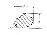
本発明でいう偏平状とは次のように定義する。コア粒子を平面上に安定して静止させた時の粒子の平面図(図1)について、輪郭に接する二つの平行線の最短距離を短径αとし、それと直角方向の平行線の最大距離を長径βとし、一方、図1に対応する側面図(図2)のように水平面に平行で粒子表面に接する平行面との間隔を厚さTとした場合に、下記式(1)に示す偏平率Xが1/2以下であり、好ましくは1/7〜1/2である。
X=T/[(α+β)/2]……式(1)
The core particles used in the present invention must be flat. If the core particles are flat, the resin-coated carrier is naturally flat.
The flat shape referred to in the present invention is defined as follows. In the plan view of the particle when the core particle is stably stopped on the plane (Fig. 1), the shortest distance between the two parallel lines in contact with the contour is the short axis α, and the maximum distance between the parallel lines in the direction perpendicular to it On the other hand, when the interval between a parallel surface parallel to the horizontal plane and in contact with the particle surface is a thickness T as shown in the side view corresponding to FIG. 1 (FIG. 2), the flatness shown in the following formula (1) The rate X is 1/2 or less, preferably 1/7 to 1/2.
X = T / [(α + β) / 2] (1)
本発明者はキャリアが偏平状であると樹脂皮膜により表面張力を下げた場合でも画像濃度が確保されることを見出した。偏平状であるとキャリア粒子表面でのトナー粒子への摩擦帯電性が良好であり、トナー粒子の付着が強く密になり、画像濃度が確保され、偏平状でなく且つ球状に近づくほどトナー粒子の付着が弱く粗くなり、画像濃度が低下するものと推測される。また、偏平状であると刷毛筋が出ない、先端欠け・後端欠けが出ない(画像の先端と後端で濃度差がない)、ハーフトーンの再現性が良いなどの利点がある。また、扁平状であると、衝撃が和らげられ、スペントや剥がれが発生しにくい。さらに一般的にコートキャリアは細線再現性は良いものの、ソリッド再現性に劣るが、偏平であると、ソリッド再現性もよい。 The present inventor has found that when the carrier is flat, the image density is secured even when the surface tension is lowered by the resin film. When the shape is flat, the triboelectric chargeability to the toner particles on the surface of the carrier particles is good, the adhesion of the toner particles becomes strong and dense, the image density is ensured, and the toner particles become more spherical as they become closer to a spherical shape. It is presumed that the adhesion becomes weak and rough, and the image density decreases. Further, the flat shape has advantages such as no brush stripes, no leading edge and trailing edge defects (no difference in density between the leading and trailing edges of the image), and good halftone reproducibility. Moreover, when it is flat, the impact is relieved and spent and peeling are less likely to occur. Furthermore, although the coat carrier generally has good fine line reproducibility, it is inferior in solid reproducibility, but if it is flat, the solid reproducibility is good.
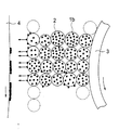
この機構について図3〜6の偏平キャリアと球形キャリアとのモデル的比較に基づき説明する。
(接触現像の場合)
図3に示すように、キャリア形状が偏平の場合、キャリアの偏平部が鎖状に連結した磁気ブラシを形成していて、偏平キャリア1aの主として偏平部に摩擦帯電によって帯電したトナーが付着している。先端側の磁気ブラシは、感光体ドラム周面をなぞるようにして摺擦するので画像濃度が出やすく、他の部分に一時的に付着したトナー粒子は磁気ブラシによって掃き取られて良好な現像が行われる。
一方、図4に示すように、キャリア形状が球形1bの場合、磁気ブラシは隣接する磁気ブラシ同士が密着して均等で高密な現像剤層を形成し、感光体表面を摺擦する現像剤層による摺擦力は偏平キャリアに比べて強く、球形キャリアでは表面積が小さく付着トナーが少なくもあるので、画像濃度が出にくい。
なお、図3〜6において3は現像スリーブ、4は感光体を示す。
This mechanism will be described based on a model comparison between the flat carrier and the spherical carrier in FIGS.
(For contact development)
As shown in FIG. 3, when the carrier shape is flat, a magnetic brush is formed in which the flat portions of the carrier are connected in a chain shape, and toner charged by frictional charging adheres mainly to the flat portion of the
On the other hand, as shown in FIG. 4, when the carrier shape is spherical 1b, the magnetic brushes are adjacent to each other to form a uniform and dense developer layer, and a developer layer that rubs the surface of the photoreceptor. The rubbing force due to is stronger than that of a flat carrier, and a spherical carrier has a small surface area and a small amount of adhering toner, so that it is difficult to obtain an image density.
3 to 6,
(非接触現像の場合)
図5に示すように、キャリア形状が偏平の場合、キャリアの偏平部が鎖状に連結した磁気ブラシを形成していて、偏平キャリア1aの主として偏平部に摩擦帯電によって帯電したトナーが付着している。現像バイアスが印加されると最上層は勿論中間に位置した偏平キャリアからもトナー粒子が飛翔して、潜像部分に付着し、高濃度でムラのない良好な画像が得られる。
一方、図6に示すように、球形キャリア1bの場合は、磁気ブラシは隣接する磁気ブラシ同士が密着して均等で高密な現像剤層を形成し、主として最上層のキャリアに付着したトナー粒子のみが現像に寄与し、球形キャリアでは表面積が小さく付着トナーが少なくもあるので、画像濃度が出にくい。
(Non-contact development)
As shown in FIG. 5, when the carrier shape is flat, a magnetic brush is formed in which the flat portions of the carrier are connected in a chain shape, and toner charged by frictional charging adheres mainly to the flat portion of the
On the other hand, as shown in FIG. 6, in the case of the
本発明の電子写真用キャリアに用いられるコア粒子としては、重量平均粒径が30〜120μmであることが好ましく、40〜110μmであることがさらに好ましい。重量平均粒径が30μm未満では、磁気ブラシの穂立ちが短くて画像濃度が出にくい。120μmを越えると穂立ちが長すぎて画像が粗くなる。なお、重量平均粒径は、電磁式篩振とう機(アルフレッド・フリッチュ社製 A−3)を用いてJIS Z8815−1994に準じふるい分けし算出したD50値(重量累積50%値)である。
なお、樹脂皮膜で被覆後のキャリアの重量平均粒子径もコアー粒子と同程度であることが好ましい。
コア粒子の材質としては、通常キャリアとして使用されているものであれば使用可能であり、ガラスビーズ、鉄粉、フェライト粉、マグネタイト粉、バインダ型のもの(磁性粒子を分散した樹脂粒子)などが例示される。本発明においては、鉄粉、フェライト粉、マグネタイト粉より選ばれる少なくとも1種であることが好ましい。これらの中でも還元鉄粉(海綿鉄粉、スポンジパウダー)が好ましい。還元鉄粉は、海綿状であり粒子内部に多数の気孔をもつことが特長で、見掛密度が小さくキャリア用として適しているし、また偏平状に加工しやすい。偏平粒子は通常、不定形乃至球状粒子を物理的につぶして得られる。海綿状の還元鉄粉をコア粒子としたキャリアの例を図8に、また、偏平状の還元鉄粉をコア粒子としたキャリアの例を図7に示した。
The core particles used in the electrophotographic carrier of the present invention preferably have a weight average particle size of 30 to 120 μm, and more preferably 40 to 110 μm. When the weight average particle diameter is less than 30 μm, the magnetic brush heads are short and image density is difficult to be obtained. If it exceeds 120 μm, the ears are too long and the image becomes rough. The weight average particle diameter is a D50 value (50% weight cumulative value) calculated by sieving according to JIS Z8815-1994 using an electromagnetic sieve shaker (A-3 manufactured by Alfred Fritsch).
In addition, it is preferable that the weight average particle diameter of the carrier after coat | covering with a resin film is also comparable as a core particle.
The material of the core particle can be used as long as it is usually used as a carrier, such as glass beads, iron powder, ferrite powder, magnetite powder, binder type (resin particles in which magnetic particles are dispersed), etc. Illustrated. In the present invention, at least one selected from iron powder, ferrite powder, and magnetite powder is preferable. Among these, reduced iron powder (sponge iron powder, sponge powder) is preferable. The reduced iron powder is spongy and has a large number of pores inside the particles, has a low apparent density, is suitable for carriers, and is easy to process into a flat shape. Flat particles are usually obtained by physically crushing irregular or spherical particles. An example of a carrier using sponge-like reduced iron powder as core particles is shown in FIG. 8, and an example of a carrier using flat reduced iron powder as core particles is shown in FIG.
本発明の電子写真用二成分現像剤に用いるトナーは、少なくとも結着樹脂、着色剤及び融点60〜105℃の低融点ワックスを含有するものである。
結着樹脂としては、通常トナーに使用されているものであれば特に限定されず、ポリスチレン系樹脂、ポリアクリル酸エステル系樹脂、スチレンーアクリル酸エステル共重合体系樹脂、スチレンーメタクリル酸エステル共重合体系樹脂、ポリ塩化ビニル、ポリ酢酸ビニル、ポリ塩化ビニリデン、フェノール樹脂、エポキシ樹脂、ポリエステル系樹脂、水添ロジン、ポリオレフィン系樹脂、シクロオレフィン共重合体樹脂、環化ゴム、ポリ乳酸樹脂、テルペンフェノール樹脂等が単独、または複数種類混合して使用できる。
The toner used in the two-component developer for electrophotography of the present invention contains at least a binder resin, a colorant, and a low melting point wax having a melting point of 60 to 105 ° C.
The binder resin is not particularly limited as long as it is usually used in toners. Polystyrene resins, polyacrylate resins, styrene-acrylate copolymer resins, styrene-methacrylate copolymers System resin, polyvinyl chloride, polyvinyl acetate, polyvinylidene chloride, phenol resin, epoxy resin, polyester resin, hydrogenated rosin, polyolefin resin, cycloolefin copolymer resin, cyclized rubber, polylactic acid resin, terpene phenol Resins or the like can be used alone or in combination.
本発明の電子写真用二成分現像剤に用いるトナーの着色剤としては、通常トナーに使用されているものであれば特に限定されず、カーボンブラック、アニリンブルー、カルコオイルブルー、クロムイエロー、ウルトラマリンブルー、デュポンオイルレッド、キノリンイエロー、メチレンブルークロライド、フタロシアニンブルー、マラカイトグリーンオキサレート、ランプブラック、ローズベンガル、酸化鉄、フェライトなどがある。着色剤は、十分な濃度の可視像が形成されるのに十分な割合の含有量が必要であり、例えば、トナー粒子に対して1〜20重量%程度、好ましくは1〜10重量%の割合で含有される。 The colorant of the toner used in the two-component developer for electrophotography of the present invention is not particularly limited as long as it is usually used in toner, and carbon black, aniline blue, calco oil blue, chrome yellow, ultramarine Blue, DuPont oil red, quinoline yellow, methylene blue chloride, phthalocyanine blue, malachite green oxalate, lamp black, rose bengal, iron oxide, ferrite, etc. The colorant must have a sufficient content to form a visible image having a sufficient density. For example, the colorant is about 1 to 20% by weight, preferably 1 to 10% by weight, based on the toner particles. Contained in proportions.
本発明の電子写真用二成分現像剤に用いるトナーは、低温定着性と定着時の離型性向上のため、融点60〜105℃の低融点ワックスを含有することが必要である。該低融点ワックスの融点は、好ましくは70〜100℃、さらに好ましくは80〜100℃である。低融点ワックスの融点が60℃未満では、トナー粒子のブロッキングが起こりやすく保存安定性が悪化し、105℃を越えると低温定着性が不十分となり低温での定着強度が弱くなる。
該低融点ワックスは、トナー粒子に対して5〜25重量%含有されていることが好ましく、5〜20重量%含有することがより好ましく、7〜15重量%含有されていることがさらに好ましい。低融点ワックスの含有量が5重量%未満では低温定着性が不十分で、且つ離型性への寄与も不十分である。25重量%を越えると、保存安定性に問題を生じるようになり、またトナー粒子から分離しやすくなりキャリアスペントを生じるようになる。
このようなワックスとしては、ポリエチレンワックス等のポリオレフィン系ワックス、フィッシャートロプシュワックス等の合成ワックス、パラフィンワックス、マイクロクリスタリンワックス等の石油系ワックス、カルナウバワックス、キャンデリラワックス、ライスワックス、硬化ひまし油、モンタンワックス、高級脂肪酸及びそのエステル、脂肪酸アミド等が挙げられる。これらの内、カルナウバワックス、フィッシャートロプシュワックスが好ましい。
The toner used in the two-component developer for electrophotography of the present invention needs to contain a low melting point wax having a melting point of 60 to 105 ° C. in order to improve low temperature fixability and releasability at the time of fixing. The melting point of the low melting point wax is preferably 70 to 100 ° C, more preferably 80 to 100 ° C. If the melting point of the low-melting wax is less than 60 ° C., the toner particles are likely to be blocked, and the storage stability is deteriorated. If the melting point exceeds 105 ° C., the low-temperature fixing property becomes insufficient and the fixing strength at low temperature becomes weak.
The low melting point wax is preferably contained in an amount of 5 to 25% by weight based on the toner particles, more preferably 5 to 20% by weight, and even more preferably 7 to 15% by weight. When the content of the low melting point wax is less than 5% by weight, the low-temperature fixability is insufficient and the contribution to the releasability is also insufficient. If it exceeds 25% by weight, a problem arises in storage stability, and it becomes easy to separate from the toner particles, resulting in carrier spent.
Examples of such wax include polyolefin wax such as polyethylene wax, synthetic wax such as Fischer-Tropsch wax, petroleum wax such as paraffin wax and microcrystalline wax, carnauba wax, candelilla wax, rice wax, hardened castor oil, montan Examples thereof include waxes, higher fatty acids and esters thereof, and fatty acid amides. Of these, carnauba wax and Fischer-Tropsch wax are preferred.
本発明の電子写真用二成分現像剤に用いるトナーは、定着時の離型性、オフセット防止のために、融点120〜160℃の高融点ワックスを含有することが好ましい。
融点が120℃未満では、オフセット防止や定着ローラーの汚染防止の効果が少なく、160℃を越えると、定着強度を弱める傾向となる。
高融点ワックスの含有量は、トナー粒子に対して1〜10重量%であることが好ましい。1重量%未満では、高温オフセット防止や定着ローラーの汚染防止の効果が少なく、10重量%を越えると、定着強度を弱める傾向となる。
さらに、低融点ワックスと高融点ワックスの含有量の合計は、トナー粒子に対して25重量%以下が好ましく、20重量%以下であることがより好ましい。25重量%を越えると、トナーの保存安定性の低下や、ワックスによるキャリアスペントの発生の問題が生じる。
The toner used in the two-component developer for electrophotography of the present invention preferably contains a high-melting-point wax having a melting point of 120 to 160 ° C. in order to prevent releasability during fixing and to prevent offset.
If the melting point is less than 120 ° C., the effect of preventing offset and fouling of the fixing roller is small, and if it exceeds 160 ° C., the fixing strength tends to be weakened.
The content of the high melting point wax is preferably 1 to 10% by weight based on the toner particles. If it is less than 1% by weight, the effect of preventing high temperature offset and fouling of the fixing roller is small, and if it exceeds 10% by weight, the fixing strength tends to be weakened.
Further, the total content of the low melting point wax and the high melting point wax is preferably 25% by weight or less, more preferably 20% by weight or less, based on the toner particles. If it exceeds 25% by weight, problems such as a decrease in storage stability of the toner and generation of carrier spent due to wax occur.
ワックスの融点は、示差走査熱量計(DSC)での吸熱ピーク温度であり、測定方法はASTM:D3418−82に準じ下記の通りである。
試料を約5mg計量してアルミ製セルに入れて、示差走査熱量計(DSC)(セイコー電子工業社製、商品名:SSC−5200)に載置し、1分間に50mlのN2ガスを吹き込む。そして、20〜200℃の間を1分間あたり10℃の割合で昇温させ、200℃で10分間保持し、次に200℃から20℃に1分間あたり10℃の割合で降温させ、次に上記条件で2回目の昇温をしその時の吸熱ピーク温度を融点とする。
The melting point of the wax is the endothermic peak temperature in a differential scanning calorimeter (DSC), and the measuring method is as follows according to ASTM: D3418-82.
About 5 mg of a sample is weighed and placed in an aluminum cell, placed on a differential scanning calorimeter (DSC) (trade name: SSC-5200, manufactured by Seiko Denshi Kogyo Co., Ltd.), and 50 ml of N 2 gas is blown into one minute. . The temperature is raised between 20 ° C. and 200 ° C. at a rate of 10 ° C. per minute, held at 200 ° C. for 10 minutes, then lowered from 200 ° C. to 20 ° C. at a rate of 10 ° C. per minute, Under the above conditions, the temperature is raised for the second time, and the endothermic peak temperature at that time is defined as the melting point.
本発明の電子写真用二成分現像剤に用いるトナーは、必要に応じて帯電制御剤を含有することが好ましい。帯電制御剤は、トナー粒子に極性を付与するために添加され、正帯電トナー用と負帯電トナー用とがあるが、これらを併用する場合もある。正帯電トナー用としては、ニグロシン染料、第4級アンモニウム塩、ピリジニウム塩、アジン、トリフェニルメタン系化合物及びカチオン性官能基を有する低分子量ポリマー等が用いられる。また、負帯電トナー用としては、アゾ系含金属錯体、サリチル酸系金属錯体、ホウ素系錯体、及びアニオン性官能基を有する低分子量ポリマー等が用いられる。
好ましい添加量は、トナー粒子に対して0.1〜5重量部である。
The toner used in the two-component developer for electrophotography of the present invention preferably contains a charge control agent as required. The charge control agent is added for imparting polarity to the toner particles, and there are a positive charge toner and a negative charge toner, and these may be used in combination. For positively charged toners, nigrosine dyes, quaternary ammonium salts, pyridinium salts, azines, triphenylmethane compounds, low molecular weight polymers having cationic functional groups, and the like are used. For negatively charged toners, azo metal-containing complexes, salicylic acid metal complexes, boron complexes, and low molecular weight polymers having an anionic functional group are used.
A preferable addition amount is 0.1 to 5 parts by weight with respect to the toner particles.
本発明の二成分現像剤に用いるトナーは、磁性粉をトナー粒子に対して40重量%以下の範囲で含有する場合もある。磁性粉としては、フェライト粉、マグネタイト粉、鉄粉等の微粒子が挙げられる。フェライト粉としてはMeO―Fe2O3の混合焼結体が本発明に使用できる。この場合のMeOは、Mn、Zn、Ni、Ba、Co、Cu、Li、Mg、Cr、Ca、V等の酸化物を意味し、そのいずれかの1種または2種以上を用いることができる。また、マグネタイト粉としてはFeO−Fe2O3の混合焼結体が使用される。磁性粉は、粒径0.05〜3μmのものが好ましい。 The toner used for the two-component developer of the present invention may contain magnetic powder in an amount of 40% by weight or less based on the toner particles. Examples of the magnetic powder include fine particles such as ferrite powder, magnetite powder, and iron powder. As the ferrite powder, a mixed sintered body of MeO—Fe 2 O 3 can be used in the present invention. MeO in this case means oxides such as Mn, Zn, Ni, Ba, Co, Cu, Li, Mg, Cr, Ca, and V, and any one or more of them can be used. . As the magnetite powder, a mixed sintered body of FeO—Fe 2 O 3 is used. The magnetic powder preferably has a particle size of 0.05 to 3 μm.
本発明の電子写真用二成分現像剤に用いるトナーは、上記材料及び必要に応じて使用するその他の材料を所定の割合で配合して混合し、その混合物を、溶融混練、粉砕、分級等の工程を経て製造することができる。また、上記材料を用いて、懸濁重合法など他の造粒法によりトナー粒子を作製してもよい。トナー粒子の体積平均粒子径(コールターマルチサイザーIIで測定した体積50%径)は、一般に5〜15μmの範囲に設定される。5μm未満では、帯電不良、トナー飛散が起こりやすくなる。15μmを越えると画像の荒れが目立つようになり、画質が低下する。さらには、解像力が優れ、濃淡差も忠実に再現した鮮明な画像を得るには10μm以下が好ましい。 The toner used in the two-component developer for electrophotography of the present invention is a mixture of the above-mentioned materials and other materials to be used as necessary at a predetermined ratio, and the mixture is melt-kneaded, pulverized, classified, etc. It can be manufactured through a process. In addition, toner particles may be produced using the above materials by other granulation methods such as suspension polymerization. The volume average particle diameter of toner particles (50% diameter measured by Coulter Multisizer II) is generally set in the range of 5 to 15 μm. If it is less than 5 μm, charging failure and toner scattering tend to occur. If it exceeds 15 μm, the roughness of the image becomes conspicuous and the image quality deteriorates. Furthermore, it is preferably 10 μm or less in order to obtain a clear image having excellent resolution and faithfully reproducing the density difference.
本発明の電子写真用二成分現像剤に用いるトナーは、流動化剤としてトナー粒子に対してシリカ微粒子が0.2〜2.0重量%付着していることが好ましい。シリカ微粒子の付着量が0.2重量%未満では、トナーの流動性が悪いためトナーの供給不良や保存性の悪化をもたらす。2.0重量%を越えるとシリカの脱離が発生しやすく、感光体のフィルミング、シリカによるキャリアスペント等の問題を引き起こすため好ましくない。シリカは疎水性シリカであることが好ましい。 The toner used in the two-component developer for electrophotography of the present invention preferably has 0.2 to 2.0% by weight of silica fine particles attached to the toner particles as a fluidizing agent. If the adhesion amount of the silica fine particles is less than 0.2% by weight, the toner fluidity is poor, leading to poor toner supply and poor storage stability. Exceeding 2.0% by weight is not preferable because silica is easily detached and causes problems such as filming of the photoreceptor and carrier spent by silica. The silica is preferably hydrophobic silica.
本発明の電子写真用二成分現像剤に用いるトナーには、シリカ微粒子の他に、トナーの流動性、帯電性、クリーニング性、及び保存性等の制御のため、磁性粉、アルミナ、タルク、クレー、炭酸カルシウム、炭酸マグネシウム、酸化チタン、酸化亜鉛、炭化珪素、及びジルコニア等の無機微粒子、ステアリン酸マグネシウム、アテアリン酸亜鉛等の脂肪酸金属塩、各種の樹脂微粒子、またはシリコーンオイル等の外添剤が付着されていてもよい。
トナー粒子にシリカ微粒子等の外添剤を付着させるためには、タービン型攪拌機、ヘンシェルミキサー、スーパーミキサー等の一般的な攪拌機により混合して攪拌する等の方法が挙げられる。
In addition to silica fine particles, the toner used in the two-component developer for electrophotography of the present invention includes magnetic powder, alumina, talc, clay to control toner fluidity, charging property, cleaning property, storage property and the like. Inorganic fine particles such as calcium carbonate, magnesium carbonate, titanium oxide, zinc oxide, silicon carbide, and zirconia, fatty acid metal salts such as magnesium stearate and zinc atearate, various resin fine particles, or external additives such as silicone oil It may be attached.
In order to attach an external additive such as silica fine particles to the toner particles, a method of mixing and stirring with a general stirrer such as a turbine stirrer, a Henschel mixer, or a super mixer can be used.
以下、実施例に基づき本発明をより詳しく説明する。なお、実施例において「部」とは「重量部」を示すものとする。なお、本発明はこれらに限定されるものではない。 Hereinafter, the present invention will be described in more detail based on examples. In the examples, “parts” means “parts by weight”. The present invention is not limited to these.
<樹脂コートキャリアの作製>
(キャリアAの作製)
信越化学社製のシリコーン樹脂 商品名:KR211とKR251とを固形分重量比で50:50になるように混合した。
上記混合シリコーン樹脂をトルエンで稀釈し、コート用樹脂塗料を得た。次に流動床法に基づく装置、上記コート用樹脂塗料1重量部(シリコーン樹脂相当量)と還元鉄粉を偏平状にした偏平鉄粉(重量平均粒径100μm、偏平率1/4.3)100部を準備した。
ついで、流動層に偏平鉄粉を浮遊状態に保ち、上記コート樹脂塗料を噴霧して偏平鉄粉の表面に付着させ、タックフリーの状態にした。ついで、60℃で24時間加熱して樹脂を硬化させた。
更に100℃で1時間熱処理を施し、最後にふるい分けをしてキャリアAを得た。キャリアAを図7に示した。
また、シリコーン樹脂の表面張力を測定するため、前記コート用樹脂塗料で鉄板表面に約30μmの皮膜を形成した後、上記電子写真用キャリアAを得たときと同一の硬化条件及び熱処理条件で鉄板上のシリコーン樹脂皮膜を処理した。そして、前記測定装置及び測定条件によって表面張力を測定した。その結果、表面張力は13dyne/cmであった。
<Production of resin-coated carrier>
(Preparation of carrier A)
Silicone resin manufactured by Shin-Etsu Chemical Co., Ltd. Trade name: KR211 and KR251 were mixed at a solid content weight ratio of 50:50.
The mixed silicone resin was diluted with toluene to obtain a coating resin coating. Next, an apparatus based on the fluidized bed method, flat iron powder (weight average particle size 100 μm, flatness ratio 1 / 4.3) obtained by flattening 1 part by weight of the coating resin paint (corresponding to silicone resin) and reduced iron powder. 100 parts were prepared.
Next, the flat iron powder was kept in a floating state in the fluidized bed, and the coating resin paint was sprayed to adhere to the surface of the flat iron powder to make it tack free. Subsequently, the resin was cured by heating at 60 ° C. for 24 hours.
Further, heat treatment was performed at 100 ° C. for 1 hour, and finally, screening was performed to obtain carrier A. Carrier A is shown in FIG.
Further, in order to measure the surface tension of the silicone resin, after forming a film of about 30 μm on the surface of the iron plate with the coating resin coating material, the iron plate is subjected to the same curing conditions and heat treatment conditions as when the electrophotographic carrier A was obtained. The top silicone resin film was treated. And surface tension was measured with the said measuring apparatus and measurement conditions. As a result, the surface tension was 13 dyne / cm.
(キャリアBの作製)
信越化学社製のシリコーン樹脂 商品名:KR211とKR251とを固形分重量比で30:70になるように混合した。
上記混合シリコーン樹脂をトルエンで稀釈し、コート用樹脂塗料を得た。次に流動床法に基づく装置、上記コート用樹脂塗料1重量部(シリコーン樹脂相当量)と、これに還元鉄粉を偏平状にした偏平鉄粉(重量平均粒径100μm、偏平率1/4.3)100部を準備した。
ついで、流動層に偏平鉄粉を浮遊状態に保ち、上記コート用樹脂塗料を噴霧して前記偏平鉄粉の表面に付着させタックフリーの状態にした。ついで、60℃で24時間加熱して樹脂を硬化させた。
更に100℃で2時間熱処理を施し、最後にふるい分けをしてキャリアBを得た。
また、シリコーン樹脂の表面張力を測定するため、前記コート用樹脂塗料で鉄板表面に約30μmの皮膜を形成した後、上記電子写真用キャリアBを得たときと同一の硬化条件及び熱処理条件で鉄板上のシリコーン樹脂皮膜を処理した。そして、前記測定装置及び測定条件によって表面張力を測定した。その結果、表面張力は21dyne/cmであった。
(Preparation of carrier B)
Silicone resin manufactured by Shin-Etsu Chemical Co., Ltd. Trade name: KR211 and KR251 were mixed at a solid content weight ratio of 30:70.
The mixed silicone resin was diluted with toluene to obtain a coating resin coating. Next, an apparatus based on a fluidized bed method, 1 part by weight of the above coating resin coating (equivalent to silicone resin), and flat iron powder obtained by flattening reduced iron powder thereon (weight average particle size 100 μm, flatness 1/4) .3) 100 parts were prepared.
Next, the flat iron powder was kept floating in the fluidized bed, and the coating resin paint was sprayed to adhere to the surface of the flat iron powder to make it tack free. Subsequently, the resin was cured by heating at 60 ° C. for 24 hours.
Further, heat treatment was performed at 100 ° C. for 2 hours, and finally, screening was performed to obtain carrier B.
Further, in order to measure the surface tension of the silicone resin, after forming a film of about 30 μm on the surface of the iron plate with the coating resin paint, the iron plate is subjected to the same curing conditions and heat treatment conditions as when the electrophotographic carrier B was obtained. The top silicone resin film was treated. And surface tension was measured with the said measuring apparatus and measurement conditions. As a result, the surface tension was 21 dyne / cm.
(キャリアCの作製)
信越化学社製のシリコーン樹脂 商品名:KR211とKR251とを固形分重量比で10:80になるように混合した。
上記混合シリコーン樹脂をトルエンで稀釈し、コート用樹脂塗料を得た。次に流動床法に基づく装置、上記コート用樹脂塗料1重量部(シリコーン樹脂相当量)と、還元鉄粉を偏平状にした偏平鉄粉(重量平均粒径100μm、偏平率1/4.3)100部を準備した。
ついで、流動層に偏平鉄粉を浮遊状態に保ち、上記コート用樹脂塗料を噴霧して前記偏平鉄粉の表面に付着させ、タックフリーの状態にした。ついで60℃で24時間加熱して樹脂を硬化させた。
更に100℃で4時間熱処理を施し、最後にふるい分けをしてキャリアCを得た。
また、シリコーン樹脂の表面張力を測定するため、前記コート用樹脂塗料で鉄板表面に約30μmの皮膜を形成した後、上記電子写真用キャリアCを得たときと同一の硬化条件及び熱処理条件で鉄板上のシリコーン樹脂皮膜を処理した。そして、前記測定装置及び測定条件によって表面張力を測定した。その結果、表面張力は29dyne/cmであった。
(Preparation of carrier C)
Silicone resin manufactured by Shin-Etsu Chemical Co., Ltd. Trade name: KR211 and KR251 were mixed at a solid content weight ratio of 10:80.
The mixed silicone resin was diluted with toluene to obtain a coating resin coating. Next, an apparatus based on a fluidized bed method, 1 part by weight of the coating resin paint (corresponding to silicone resin), and flat iron powder (weight average particle size 100 μm, flatness ratio 1 / 4.3) obtained by flattening reduced iron powder. ) 100 parts were prepared.
Next, the flat iron powder was kept in a floating state in the fluidized bed, and the coating resin coating material was sprayed to adhere to the surface of the flat iron powder to make it tack free. Next, the resin was cured by heating at 60 ° C. for 24 hours.
Further, heat treatment was performed at 100 ° C. for 4 hours, and finally, screening was performed to obtain carrier C.
Further, in order to measure the surface tension of the silicone resin, after forming a film of about 30 μm on the surface of the iron plate with the coating resin coating material, the iron plate is subjected to the same curing conditions and heat treatment conditions as when the electrophotographic carrier C was obtained. The top silicone resin film was treated. And surface tension was measured with the said measuring apparatus and measurement conditions. As a result, the surface tension was 29 dyne / cm.
(キャリアDの作製)
100℃、1時間の熱処理を施さなかったこと以外はキャリアAと同様にしてキャリアDを得た。キャリアDの樹脂皮膜の表面張力は7dyne/cmであった。
(Preparation of carrier D)
Carrier D was obtained in the same manner as Carrier A except that heat treatment was not performed at 100 ° C. for 1 hour. The surface tension of the resin film of carrier D was 7 dyne / cm.
(キャリアEの作製)
100℃、4時間の熱処理に代えて100℃、10時間の熱処理を施したこと以外はキャリアCと同様にしてキャリアEを得た。キャリアEの樹脂皮膜の表面張力は36dyne/cmであった。
(Preparation of carrier E)
Carrier E was obtained in the same manner as Carrier C except that the heat treatment was performed at 100 ° C. for 10 hours instead of the heat treatment at 100 ° C. for 4 hours. The surface tension of the resin film of carrier E was 36 dyne / cm.
(キャリアFの作製)
コア粒子として、偏平状にしていない不定形(海綿状)還元鉄粉(重量平均粒子径65μm、偏平率1/1.1)を使用した以外は、キャリアBと同様にしてキャリアFを作製した。キャリアFの樹脂皮膜の表面張力は21dyne/cmであった。キャリアFを図8に示した。
(Preparation of carrier F)
Carrier F was prepared in the same manner as carrier B, except that amorphous (sponge-like) reduced iron powder (weight average particle diameter 65 μm, flatness 1 / 1.1) not flattened was used as the core particles. The surface tension of the resin film of the carrier F was 21 dyne / cm. Carrier F is shown in FIG.
<トナーの作製>
(トナーAの作製)
スチレンーアクリル酸エステル共重合体樹脂 75.5重量%
(三洋化成工業社製 商品名:TB−100F)
カルナウバワックス 10.0重量%
(加藤洋行社製 商品名:カルナウバ1級、融点82℃)
ポリプロピレンワックス 3.0重量%
(三洋化成工業社製 商品名:ビスコール550P、融点152℃)
カーボンブラック 10.0重量%
(キャボット社製 商品名:リーガル330R)
含金属染料 1.5重量%
(保土谷化学工業社製 商品名:スピロンブラックTRH)
上記の配合比からなる原料をスーパーミキサーで10分間混合し、2軸のエクストルーダーにて熱溶融混練した後、冷却し、ジェットミルにて粉砕し、その後乾式気流分級機で分級して体積平均粒子径が10μmの負極性の非磁性トナー粒子を得た。そして、該トナー粒子100重量部に対して疎水性シリカ(日本アエロジル社製、商品名:R972)の付着量0.5重量部になるように調整し、ヘンシェルミキサーにて混合してトナーAを得た。
<Production of toner>
(Preparation of Toner A)
Styrene-acrylic acid ester copolymer resin 75.5% by weight
(Product name: TB-100F, manufactured by Sanyo Chemical Industries)
Carnauba wax 10.0% by weight
(Product name: Yoko Kato, trade name: Carnauba grade 1, melting point 82 ° C)
Polypropylene wax 3.0% by weight
(Trade name: Viscol 550P, melting point 152 ° C., manufactured by Sanyo Chemical Industries)
Carbon black 10.0% by weight
(Product name: Legal 330R manufactured by Cabot)
Metal-containing dye 1.5% by weight
(Product name: Spiron Black TRH, manufactured by Hodogaya Chemical Co., Ltd.)
The raw materials having the above blending ratio are mixed for 10 minutes with a super mixer, hot melt kneaded with a twin-screw extruder, cooled, pulverized with a jet mill, and then classified with a dry air classifier to obtain a volume average. Negative-polarity non-magnetic toner particles having a particle diameter of 10 μm were obtained. Then, the amount of hydrophobic silica (trade name: R972, manufactured by Nippon Aerosil Co., Ltd.) is adjusted to 0.5 parts by weight with respect to 100 parts by weight of the toner particles, and the toner A is mixed by a Henschel mixer. Obtained.
(トナーBの作製)
スチレンーアクリル共重合体樹脂を85.5重量%、カルナウバワックスを0重量%としたこと以外は、トナーAと同様にしてトナーBを得た。
(Preparation of Toner B)
Toner B was obtained in the same manner as Toner A, except that the styrene-acrylic copolymer resin was 85.5 wt% and carnauba wax was 0 wt%.
<二成分現像剤の作製>
キャリアA〜FとトナーA〜Bとをキャリア100部に対してトナーを4部混合して二成分現像剤を作製した。
キャリアとトナー組み合わせは下記の通りである。
(二成分現像剤A)キャリアAとトナーA・・実施例1
(二成分現像剤B)キャリアBとトナーA・・実施例2
(二成分現像剤C)キャリアCとトナーA・・実施例3
(二成分現像剤D)キャリアDとトナーA・・比較例1
(二成分現像剤E)キャリアEとトナーA・・比較例2
(二成分現像剤F)キャリアFとトナーA・・比較例3
(二成分現像剤G)キャリアAとトナーB・・比較例4
<Preparation of two-component developer>
A carrier A to F and toners A to B were mixed with 4 parts of toner with respect to 100 parts of carrier to prepare a two-component developer.
The carrier and toner combinations are as follows.
(Two-component developer A) Carrier A and toner A .. Example 1
(Two-component developer B) Carrier B and toner A .. Example 2
(Two-component developer C) Carrier C and toner A .. Example 3
(Two-component developer D) Carrier D and toner A. Comparative Example 1
(Two-component developer E) Carrier E and toner A. Comparative Example 2
(Two-component developer F) Carrier F and toner A. Comparative Example 3
(Two-component developer G) Carrier A and toner B, Comparative Example 4
次にこれらの現像剤を使用して、25℃、50%RHの環境下で、複写機(東芝社製 商品名:BD−9110,接触現像方式、A4コピー速度10枚/分)を使用して120000枚連続コピーを実施し、その結果を表1に示した。 Next, using these developers, using a copying machine (product name: BD-9110, contact development method, A4 copy speed 10 sheets / minute, manufactured by Toshiba) in an environment of 25 ° C. and 50% RH. 120,000 sheets were continuously copied, and the results are shown in Table 1.
なお、各特性の評価に使用した試験装置及び測定方法は次の通りである。
(1) 画像濃度・・マクベス反射濃度計RD−914によりベタ画像部の反射濃度を測定した。
(2) 地カブリ・・白色計MODEL Z−1001DP(日本電飾工業社製)を用い、複写後の転写紙の非画像部の白色度と、複写前の転写紙の白色度との差を地カブリとした。
(3) スペント・・120000枚連続コピー後の各現像剤から各キャリアを分離し、その重量を測定しAgとした。次に各キャリアを石鹸水で洗浄したのち、トルエンで洗浄し、洗浄後の重量を測定しBgとした。
そして、スペント(重量%)=[(A−B)/A]×100 として算出した。
(4) 樹脂皮膜の剥がれ・・使用前のキャリアの炭素量と使用後の洗浄済キャリアの炭素量を炭素分析装置(HORIBA社製 商品名:CARBON ANALYZER EMIA―110)で測定し、炭素含有量の差からコート樹脂の剥がれ(重量%)を算出し、次の基準で評価した。
○:10重量%未満、△:10〜30重量%、×:30重量%を越える。
(5) 定着強度・・25mm×25mmのベタ画像部を500g/cm2の荷重をかけた砂消しゴムで往復3回擦り、その前後の画像濃度を測定し次式により定着強度を求めた。
(擦った後の画像濃度/擦る前の画像濃度)×100(%)
評価基準 ○:80%を越える、△:60〜80%、×:60%未満
In addition, the test apparatus and measurement method used for evaluation of each characteristic are as follows.
(1) Image density: The reflection density of the solid image portion was measured with a Macbeth reflection densitometer RD-914.
(2) Using a ground fogging white meter MODEL Z-1001DP (manufactured by Nippon Denshoku Kogyo Co., Ltd.), the difference between the whiteness of the non-image area of the transfer paper after copying and the whiteness of the transfer paper before copying is calculated. It was ground fog.
(3) Spent. Each carrier was separated from each developer after continuous copying of 120,000 sheets, and its weight was measured to be Ag. Next, each carrier was washed with soapy water and then with toluene, and the weight after washing was measured to obtain Bg.
And it was computed as spent (weight%) = [(A−B) / A] × 100.
(4) Peeling of the resin film: Measure the carbon content of the carrier before use and the carbon content of the washed carrier after use with a carbon analyzer (trade name: CARBON ANALYZER EMIA-110, manufactured by HORIBA). The coating resin peeling (% by weight) was calculated from the difference between the values and evaluated according to the following criteria.
○: Less than 10% by weight, Δ: 10-30% by weight, ×: More than 30% by weight.
(5) Fixing strength: A solid image portion of 25 mm × 25 mm was rubbed back and forth three times with a sand eraser applied with a load of 500 g / cm 2 , the image density before and after that was measured, and the fixing strength was determined by the following formula.
(Image density after rubbing / Image density before rubbing) × 100 (%)
Evaluation criteria ○: Over 80%, Δ: 60-80%, X: Less than 60%
表1から明らかなように、実施例1〜3の本発明の電子写真用二成分現像剤による画像は、120000枚連続コピーした後も安定した画像特性を有していた。つまり、地カブリが少なく、画像濃度も1.39以上であり安定していた。また、120000枚連続コピー後のキャリアのスペントも少なく、剥がれ、定着強度も問題ないレベルであった。
一方、表面張力が本発明の特定する範囲に満たないキャリアDを使用した比較例1の二成分現像剤Dを使用した場合は、画像濃度が小さく剥がれが発生した。
表面張力が本発明の特定する範囲を越えるキャリアEを使用した比較例2の二成分現像剤Eを使用した場合は、画像濃度が小さく、且つ120000枚連続コピー後の地カブリが多かった。また、スペントも多く、剥がれがやや多かった。
偏平でない不定形コア粒子を使用したキャリアFを使用した比較例3の二成分現像剤Fを使用した場合は、画像濃度が小さかった。また、地カブリ、スペント、剥がれも多目であった。
低融点ワックスを使用していないトナーBを使用した比較例4の二成分現像剤Gを使用した場合は、定着強度が弱かった。
As is apparent from Table 1, the images obtained by the two-component developer for electrophotography of Examples 1 to 3 of the present invention had stable image characteristics even after continuous copying of 120,000 sheets. That is, the background fogging was small, and the image density was 1.39 or more and stable. Also, the spent of the carrier after continuous copying of 120,000 sheets was small, peeling and fixing strength were at a level with no problem.
On the other hand, when the two-component developer D of Comparative Example 1 using the carrier D whose surface tension is less than the range specified by the present invention was used, the image density was small and peeling occurred.
When the two-component developer E of Comparative Example 2 using the carrier E having a surface tension exceeding the range specified by the present invention was used, the image density was small and the background fogging after 120,000 continuous copies was large. In addition, there were many spents, and there was a little peeling.
When the two-component developer F of Comparative Example 3 using the carrier F using non-flat amorphous core particles was used, the image density was small. In addition, ground fog, spent, and peeling were prominent.
When the two-component developer G of Comparative Example 4 using the toner B that does not use the low melting point wax was used, the fixing strength was weak.
1 コア粒子
1a 偏平キャリア
1b 球形キャリア
2 トナー
3 現像スリーブ
4 感光体
α 短径
β 長径
T 厚さ
1
Claims (7)
The two-component developer for electrophotography according to claim 5 or 6, wherein the toner particles contain a high melting point wax having a melting point of 120 to 160 ° C.
Priority Applications (1)
| Application Number | Priority Date | Filing Date | Title |
|---|---|---|---|
| JP2004019635A JP2005215136A (en) | 2004-01-28 | 2004-01-28 | Electrophotographic carrier and electrophotographic two-component developer using same |
Applications Claiming Priority (1)
| Application Number | Priority Date | Filing Date | Title |
|---|---|---|---|
| JP2004019635A JP2005215136A (en) | 2004-01-28 | 2004-01-28 | Electrophotographic carrier and electrophotographic two-component developer using same |
Publications (2)
| Publication Number | Publication Date |
|---|---|
| JP2005215136A true JP2005215136A (en) | 2005-08-11 |
| JP2005215136A5 JP2005215136A5 (en) | 2006-09-14 |
Family
ID=34903795
Family Applications (1)
| Application Number | Title | Priority Date | Filing Date |
|---|---|---|---|
| JP2004019635A Pending JP2005215136A (en) | 2004-01-28 | 2004-01-28 | Electrophotographic carrier and electrophotographic two-component developer using same |
Country Status (1)
| Country | Link |
|---|---|
| JP (1) | JP2005215136A (en) |
Cited By (2)
| Publication number | Priority date | Publication date | Assignee | Title |
|---|---|---|---|---|
| JP2010169836A (en) * | 2009-01-21 | 2010-08-05 | Sharp Corp | Resin coated carrier, two-component developer, development device, and image forming apparatus |
| JP2014103380A (en) * | 2012-10-26 | 2014-06-05 | Sumitomo Metal Mining Co Ltd | Coating film and formation method of the same, and light-emitting diode device using the coating film |
-
2004
- 2004-01-28 JP JP2004019635A patent/JP2005215136A/en active Pending
Cited By (4)
| Publication number | Priority date | Publication date | Assignee | Title |
|---|---|---|---|---|
| JP2010169836A (en) * | 2009-01-21 | 2010-08-05 | Sharp Corp | Resin coated carrier, two-component developer, development device, and image forming apparatus |
| JP4741684B2 (en) * | 2009-01-21 | 2011-08-03 | シャープ株式会社 | Two-component developer, developing device and image forming apparatus |
| US8409778B2 (en) | 2009-01-21 | 2013-04-02 | Sharp Kabushiki Kaisha | Resin coated carrier, two-component developer, developing device and image forming apparatus |
| JP2014103380A (en) * | 2012-10-26 | 2014-06-05 | Sumitomo Metal Mining Co Ltd | Coating film and formation method of the same, and light-emitting diode device using the coating film |
Similar Documents
| Publication | Publication Date | Title |
|---|---|---|
| JP4625417B2 (en) | Carrier and two-component developer | |
| JP4728903B2 (en) | Carrier and developer, and image forming method, image forming apparatus, and process cartridge | |
| EP1589381A2 (en) | Resin coated carrier for electrophotography and two-component developer for electrophotography made therefrom | |
| JP6743392B2 (en) | Carrier, developer, image forming apparatus, process cartridge and image forming method | |
| JP2000010337A (en) | Toner, binary developer, and electrophotographic device | |
| JP4852095B2 (en) | Toner for electrophotography | |
| JP2004326049A (en) | Nonmagnetic toner for development | |
| JP4989805B2 (en) | Toner evaluation method | |
| JP2005321690A (en) | Electrophotographic toner and electrophotographic two-component developer using the same | |
| EP0479875B1 (en) | Dry electrostatographic toner composition | |
| JP2005215136A (en) | Electrophotographic carrier and electrophotographic two-component developer using same | |
| JP2004325843A (en) | Electrophotographic toner | |
| JP6753147B2 (en) | Carrier for electrostatic latent image development, two-component developer, developer for replenishment, image forming apparatus, process cartridge and image forming method | |
| JP5248163B2 (en) | Coat carrier and two-component developer | |
| JPH06506782A (en) | Electrophotographic developer composition | |
| JPWO2004077166A1 (en) | Electrophotographic developer | |
| JP3845325B2 (en) | Non-magnetic one-component developing toner | |
| JP2000187359A (en) | Electrostatic latent image developing carrier and electrostatic latent image developer | |
| JP3925060B2 (en) | Electrophotographic developer and image forming apparatus | |
| JP4198491B2 (en) | Two-component developer for electrophotography and developing method using the same | |
| JP3982162B2 (en) | Image forming method and image forming apparatus | |
| JPH10307429A (en) | Electrostatic latent image developing carrier, its production, developer and image forming method | |
| JP2021076820A (en) | Carrier for electrophotographic image formation, developer for electrophotographic image formation, electrophotographic image forming method, electrophotographic image forming apparatus, and process cartridge | |
| JP3764562B2 (en) | Toner for electrophotography | |
| JP2019113717A (en) | Carrier set, two-component developer set, process cartridge, image forming apparatus, and image forming method |
Legal Events
| Date | Code | Title | Description |
|---|---|---|---|
| A521 | Written amendment |
Free format text: JAPANESE INTERMEDIATE CODE: A523 Effective date: 20060727 |
|
| A621 | Written request for application examination |
Free format text: JAPANESE INTERMEDIATE CODE: A621 Effective date: 20060727 |
|
| A131 | Notification of reasons for refusal |
Free format text: JAPANESE INTERMEDIATE CODE: A131 Effective date: 20080527 |
|
| A521 | Written amendment |
Free format text: JAPANESE INTERMEDIATE CODE: A523 Effective date: 20080728 |
|
| RD13 | Notification of appointment of power of sub attorney |
Free format text: JAPANESE INTERMEDIATE CODE: A7433 Effective date: 20080801 |
|
| A521 | Written amendment |
Free format text: JAPANESE INTERMEDIATE CODE: A821 Effective date: 20080801 |
|
| A02 | Decision of refusal |
Free format text: JAPANESE INTERMEDIATE CODE: A02 Effective date: 20090217 |