JP2005209010A - Medium identification method using magnetic tag and magnetic tag-provided medium - Google Patents
Medium identification method using magnetic tag and magnetic tag-provided medium Download PDFInfo
- Publication number
- JP2005209010A JP2005209010A JP2004015765A JP2004015765A JP2005209010A JP 2005209010 A JP2005209010 A JP 2005209010A JP 2004015765 A JP2004015765 A JP 2004015765A JP 2004015765 A JP2004015765 A JP 2004015765A JP 2005209010 A JP2005209010 A JP 2005209010A
- Authority
- JP
- Japan
- Prior art keywords
- medium
- magnetostrictive element
- magnetostrictive
- magnetic tag
- tag
- Prior art date
- Legal status (The legal status is an assumption and is not a legal conclusion. Google has not performed a legal analysis and makes no representation as to the accuracy of the status listed.)
- Granted
Links
Images


Landscapes
- Magnetic Record Carriers (AREA)
- Recording Or Reproducing By Magnetic Means (AREA)
- Credit Cards Or The Like (AREA)
Abstract
Description
この発明は、磁性タグを用いた媒体識別方法および磁性タグが付与された媒体に関し、特に、アモルファス磁歪素子を媒体に固定する固定部の面積を変化させて媒体上に形成された磁性タグが交番磁界を受けて磁歪振動する共振振動周波数に基づいて磁性タグが形成された媒体を識別する磁性タグを用いた媒体識別方法および磁性タグが付与された媒体に関する。 The present invention relates to a medium identification method using a magnetic tag and a medium to which a magnetic tag is attached, and in particular, a magnetic tag formed on a medium by changing the area of a fixing portion for fixing an amorphous magnetostrictive element to the medium is alternating. The present invention relates to a medium identification method using a magnetic tag for identifying a medium on which a magnetic tag is formed based on a resonance vibration frequency that undergoes magnetostrictive vibration in response to a magnetic field, and a medium provided with the magnetic tag.
近年、商品や用紙、その他の媒体に情報を記録したタグを形成し、これらの媒体に形成されたタグの情報を非接触またはリモートで授受する装置およびその方法が提供されている。 2. Description of the Related Art In recent years, there have been provided devices and methods for forming tags that record information on merchandise, paper, and other media, and transferring and receiving tag information formed on these media in a contactless or remote manner.
例えば、物品等の商品を扱う店舗においては、商品の盗難等を防止するために商品の物品にタグを貼付し、このタグが貼付された商品が、店舗の出入口付近にゲート状に設置されたタグ検知装置を通過した際に、これらタグ の状態を1ビットのON/OFFで感知し、清算済みかどうかを判断して万引盗難を防止するシステムがある。 For example, in a store that handles merchandise such as goods, a tag is affixed to the merchandise goods in order to prevent theft of the merchandise, and the merchandise with the tag attached is installed in a gate shape near the entrance of the store There is a system to prevent shoplifting theft by detecting the status of these tags with 1-bit ON / OFF when they pass the tag detection device and judging whether they have been cleared.
また、より多くの情報の授受が可能なように、ICチップに接続されたアンテナを介してRF帯域の電磁波を送受信するようなICカードも提供されている。 In addition, IC cards that transmit and receive RF band electromagnetic waves via an antenna connected to an IC chip are also provided so that more information can be exchanged.
しかし、このICカードは、多くの情報量を扱うことが可能であるが、製造コストや、ICカードの大きさ等により用途が制限される。 However, this IC card can handle a large amount of information, but its application is limited by the manufacturing cost, the size of the IC card, and the like.
そこで、非接触で情報の授受ができ、1ビットのON/OFFよりも、より多くの情報が表現可能な磁歪素子をタグとして用いる方法や装置が提案されている。 In view of this, a method and apparatus have been proposed that uses a magnetostrictive element as a tag that can exchange information in a non-contact manner and can express more information than 1-bit ON / OFF.
例えば、特許文献1や特許文献2および特許文献3に示されるように、磁歪素子であるアモルファス磁歪リボンを用いて、このアモルファス磁歪リボンの共振周波数によって多くの情報量が設定可能な情報記録媒体やデータタグ装置が提案がされている。
ところで、上記に示した特許文献においては、アモルファス磁歪リボンの共振周波数によって得られる情報量を増加させるために、例えば特許文献1では、長さがほぼ等しくかつ幅が互いに異なる複数のアモルファス磁歪リボンを支持体に設けるような構成とし、特許文献2では、アモルファス磁歪リボンに、その磁歪振動を制御して共振周波数を変化させる負荷手段を設けるような構成とし、特許文献3では、アモルファス磁歪リボンの磁化パターンによるバイアス磁界の大きさを異ならせるような構成として、それぞれが、より多くの情報量を表現可能としている。
By the way, in the patent document shown above, in order to increase the amount of information obtained by the resonance frequency of the amorphous magnetostrictive ribbon, for example, in
これらの提案は、いずれも高透磁率性磁歪部材が支持体内に振動可能に装填された場合の共振周波数の変化に対応付けた情報を、より多く表現可能とするような発明であり、紙のような薄い媒体に高透磁率性磁歪部材を形成し、高透磁率性磁歪部材が形成された紙等の媒体を複数重ね合わせて、それぞれの媒体に形成された高透磁率性磁歪部材を検知して媒体を特定可能とするような情報の表現方法については開示されていない。 Both of these proposals are inventions that can express more information associated with changes in the resonance frequency when a high permeability magnetostrictive member is loaded in a support body so as to vibrate. A high-permeability magnetostrictive member is formed on such a thin medium, and a plurality of media such as paper on which the high-permeability magnetostrictive member is formed are overlapped to detect the high-permeability magnetostrictive member formed on each medium. Thus, there is no disclosure of a method for expressing information that makes it possible to specify a medium.
そこで、この発明は、磁性タグを用いた媒体識別方法および磁性タグが付与された媒体に関し、特に、アモルファス磁歪素子を媒体に固定する固定部の面積を変化させて媒体上に形成された磁性タグが交番磁界を受けて磁歪振動する共振振動周波数に基づいて磁性タグが形成された媒体を識別する磁性タグを用いた媒体識別方法および磁性タグが付与された媒体を提供することを目的とする。 Therefore, the present invention relates to a medium identification method using a magnetic tag and a medium provided with a magnetic tag, and in particular, a magnetic tag formed on a medium by changing the area of a fixing portion for fixing an amorphous magnetostrictive element to the medium. It is an object of the present invention to provide a medium identification method using a magnetic tag for identifying a medium on which a magnetic tag is formed based on a resonance vibration frequency that undergoes magnetostrictive vibration in response to an alternating magnetic field, and a medium provided with the magnetic tag.
上記目的を達成するため、請求項1の発明は、媒体上に少なくとも1つの磁歪素子からなる磁性タグを付与し、所定の交番磁界中における前記磁歪素子の共振振動周波数に基づき前記磁性タグのタグ情報を読み取る磁性タグを用いた媒体識別方法において、前記磁性タグを形成する磁歪素子は、少なくとも一部が前記媒体上に固定され、前記磁歪素子を媒体に固定する固定部の面積を異ならせることにより前記所定の交番磁界中における前記磁歪素子の共振振動周波数を変化させることを特徴とする。 In order to achieve the above object, a first aspect of the present invention provides a magnetic tag comprising at least one magnetostrictive element on a medium, and the tag of the magnetic tag is based on a resonance vibration frequency of the magnetostrictive element in a predetermined alternating magnetic field. In the medium identification method using the magnetic tag for reading information, at least a part of the magnetostrictive element forming the magnetic tag is fixed on the medium, and the areas of the fixing portions for fixing the magnetostrictive element to the medium are made different. To change the resonant vibration frequency of the magnetostrictive element in the predetermined alternating magnetic field.
また、請求項2の発明は、請求項1の発明において、前記磁歪素子は、複数の磁歪素子からなり、前記タグ情報は、前記複数の磁歪素子の共振振動の周波数パターンに基づき読み取られることを特徴とする。 According to a second aspect of the present invention, in the first aspect of the invention, the magnetostrictive element includes a plurality of magnetostrictive elements, and the tag information is read based on a frequency pattern of resonance vibration of the plurality of magnetostrictive elements. Features.
また、請求項3の発明は、請求項2の発明において、前記複数の該磁歪素子は、形状が同じで該磁歪素子の固定部の面積がそれぞれ異なることを特徴とする。
The invention of
また、請求項4の発明は、請求項2の発明において、前記複数の該磁歪素子は、少なくとも1つが形状が異なることを特徴とする。
The invention of
また、請求項5の発明は、請求項1乃至4のいずれかの発明において、前記タグ情報は、前記複数の磁歪素子の共振振動の周波数パターンの一部に基づき読み取られることを特徴とする。 According to a fifth aspect of the present invention, in any one of the first to fourth aspects, the tag information is read based on part of a frequency pattern of resonance vibration of the plurality of magnetostrictive elements.
また、請求項6の発明は、少なくとも1つの磁歪素子からなる磁性タグが付与され、所定の交番磁界中における前記磁歪素子の共振振動周波数に基づき読み取られる前記磁性タグのタグ情報により識別される磁性タグが付与された媒体において、前記磁性タグを形成する磁歪素子は、少なくとも一部が前記媒体上に固定され、前記磁歪素子を媒体に固定する固定部の面積を異ならせることにより前記所定の交番磁界中における前記磁歪素子の共振振動周波数を変化させることを特徴とする。 According to a sixth aspect of the present invention, a magnetic tag comprising at least one magnetostrictive element is provided, and a magnetic tag identified by tag information of the magnetic tag read based on a resonance vibration frequency of the magnetostrictive element in a predetermined alternating magnetic field. In the medium to which the tag is attached, at least a part of the magnetostrictive element forming the magnetic tag is fixed on the medium, and the predetermined alternation is made by changing the area of the fixing portion for fixing the magnetostrictive element to the medium. The resonant vibration frequency of the magnetostrictive element in a magnetic field is changed.
また、請求項7の発明は、請求項6の発明において、前記磁歪素子は、複数の磁歪素子からなり、前記タグ情報は、前記複数の磁歪素子の共振振動の周波数パターンに基づき読み取られることを特徴とする。 According to a seventh aspect of the invention, in the sixth aspect of the invention, the magnetostrictive element comprises a plurality of magnetostrictive elements, and the tag information is read based on a frequency pattern of resonance vibration of the plurality of magnetostrictive elements. Features.
また、請求項8の発明は、請求項7の発明において、前記複数の該磁歪素子は、形状が同じで該磁歪素子の固定部の面積がそれぞれ異なることを特徴とする。
The invention of
また、請求項9の発明は、請求項7の発明において、前記複数の該磁歪素子は、少なくとも1つが形状が異なることを特徴とする。
The invention of claim 9 is characterized in that, in the invention of
また、請求項10の発明は、請求項6乃至9のいずれかの発明において、前記タグ情報は、前記複数の磁歪素子の共振振動の周波数パターンの一部に基づき読み取られることを特徴とする。 According to a tenth aspect of the present invention, in the invention according to any of the sixth to ninth aspects, the tag information is read based on a part of a frequency pattern of resonance vibration of the plurality of magnetostrictive elements.
この発明の磁性タグを用いた媒体識別方法および磁性タグが付与された媒体によれば、媒体上に少なくとも1つの磁歪素子からなる磁性タグを付与し、所定の交番磁界中における前記磁歪素子の共振振動周波数に基づき前記磁性タグのタグ情報を読み取る磁性タグを用いた媒体識別方法において、前記磁性タグを形成する磁歪素子は、少なくとも一部が前記媒体上に固定され、前記磁歪素子を媒体に固定する固定部の面積を異ならせることにより前記所定の交番磁界中における前記磁歪素子の共振振動周波数を変化させるような構成としたので、同じ形状の磁性タグであっても磁歪素子が媒体に固定された固定部の面積に対応して、より多くの情報を識別することができる。 According to the medium identifying method using the magnetic tag and the medium provided with the magnetic tag according to the present invention, the magnetic tag including at least one magnetostrictive element is provided on the medium, and the resonance of the magnetostrictive element in a predetermined alternating magnetic field is provided. In a medium identification method using a magnetic tag that reads tag information of the magnetic tag based on a vibration frequency, at least a part of the magnetostrictive element forming the magnetic tag is fixed on the medium, and the magnetostrictive element is fixed to the medium. Since the resonance vibration frequency of the magnetostrictive element in the predetermined alternating magnetic field is changed by changing the area of the fixed portion to be fixed, the magnetostrictive element is fixed to the medium even if the magnetic tag has the same shape. More information can be identified corresponding to the area of the fixed part.
また、磁性タグが付与された媒体が重ね合わさった状態であっても各媒体に付与された磁性タグの情報を読み取り、各媒体固有を特定できるという効果を奏する。 In addition, even when the medium to which the magnetic tag is attached is superposed, the information of the magnetic tag attached to each medium can be read and the uniqueness of each medium can be specified.
この発明に係わる磁性タグを用いた媒体識別方法および磁性タグが付与された媒体は、例えばダイレクトメール等を配送する場合のように、内容の異なる複数種類の原稿を一セットとして封筒やケース等の中に入れて封印後、封筒やケース等の中に入れるべき複数種類の原稿の入れ忘れがないか否かを開封することなく非接触で検知可能な磁性タグを用いた媒体識別方法および磁性タグが付与された媒体として用いることが可能である。 The medium identification method using the magnetic tag according to the present invention and the medium to which the magnetic tag is attached include, for example, an envelope, a case, etc. as a set of a plurality of types of documents having different contents, such as when direct mail is delivered. A medium identification method and a magnetic tag using a magnetic tag that can be detected in a non-contact manner without opening whether or not to forget to put a plurality of types of documents to be put in an envelope or case etc. It can be used as a given medium.
例えば、この実施例においては、この発明に係わる磁性タグが付与された媒体の複数の原稿を一セットとして封筒内に収納し、封筒外部から非接触で封筒内に収納されている各原稿を書類確認装置を用いて特定して、一セットを構成する全ての原稿が封筒内に収納されているか否かを確認する場合を想定した、この発明に係わる磁性タグを用いた媒体識別方法および磁性タグが付与された媒体について示してある。 For example, in this embodiment, a plurality of originals with a magnetic tag according to the present invention are stored as a set in an envelope, and each original stored in the envelope without contact from the outside of the envelope is a document. A medium identification method and a magnetic tag using the magnetic tag according to the present invention, which are assumed to be specified using a confirmation device to confirm whether or not all originals constituting one set are stored in an envelope. It shows about the medium to which is given.
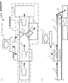
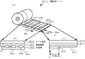
図1は、この発明に係わる磁性タグを用いた媒体識別方法および磁性タグが付与された媒体を適用した一例の書類確認装置の全体の構成を示す図である。 FIG. 1 is a diagram showing an overall configuration of an example document confirmation apparatus to which a medium identification method using a magnetic tag according to the present invention and a medium to which a magnetic tag is attached are applied.
図1(a)は、書類確認装置100の概略の平面図であり、図1(b)は、図1(a)に示した平面図に対応した側面図である。 FIG. 1A is a schematic plan view of the document confirmation apparatus 100, and FIG. 1B is a side view corresponding to the plan view shown in FIG.
図1において、書類確認装置100は、この発明に係わる磁性タグが付与された媒体を用いて作成された内容の異なる複数種類の原稿を一セットとして封筒内に収納して封印後、封筒外部から非接触で封筒内に入れるべき原稿の入れ忘れがないか否かを、この発明に係わる磁性タグを用いた媒体識別方法により確認する装置として用いられるものである。 In FIG. 1, a document checking apparatus 100 stores a plurality of types of originals having different contents created using a medium with a magnetic tag according to the present invention as a set in an envelope and seals it from the outside of the envelope. It is used as an apparatus for confirming whether or not a document to be put in an envelope without contact is forgotten by the medium identifying method using the magnetic tag according to the present invention.
図1に示すように、封筒4内に収納された図示せぬ複数の原稿には、書類確認装置100が封筒4内に収納された原稿の種類を非接触で検知可能とするために、各原稿固有を識別可能とする図示せぬ磁性タグが形成されており、この磁性タグを書類確認装置100が封筒4の外部から非接触で検知することで検知した磁性タグが形成された原稿を特定し、封筒4内に収納された原稿の種類を開封することなく検知できるように構成されている。
As shown in FIG. 1, a plurality of documents (not shown) stored in the
この書類確認装置100の構成は、封筒4内に存在する原稿に形成された磁性タグを検知する検知装置1と、検知装置1によって検知された検知結果に基づいて封筒4を封筒回収箱34または封筒配送箱33の何れかへ搬送する搬送機構装置3(一点鎖線で囲まれた部分)と、書類確認装置100全体を統括制御するコンピュータ2とで構成されている。
The configuration of the document confirmation apparatus 100 includes a
搬送機構装置3は、搬送用ベルト30と、ゲート31およびゲート31の開閉制御を行うゲート制御装置32と、封筒回収箱34および封筒配送箱33を備えている。
The
搬送用ベルト30は、図示せぬ駆動装置によって所定方向(図中の矢印35参照)に移動し、配送用ベルト30上に載せられた封筒4を検知装置1の略直下を通過させ、検知装置1の検知結果に基づいて封筒回収箱34または封筒配送箱33へ搬送する。
The
搬送用ベルト30の検知装置1の出口近傍には、板状のゲート31が配設されており、このゲート31が検知装置1の検知結果及びコンピュータ2の命令指示により開閉し、封筒4を封筒回収箱34または封筒配送箱33の何れかへ搬送するように誘導する。
A plate-
例えば、検知装置1は、検知装置1の略直下に搬送された封筒4内に収納された各原稿に形成されている磁性タグを検知し、検知した磁性タグの情報に基づいて封筒4内に複数種類の原稿で一セットを構成する全ての原稿が収納されているか否かを判断する。
For example, the
なお、封筒4内に複数種類の原稿で一セットを構成する全ての種類の原稿が収納されているか否かの判断は、予め登録された一セットを構成する複数種類の各原稿に形成された磁性タグの情報(以下、「参照情報」という。)と、検知装置1が検知した磁性タグの情報(以下、「検知情報」という。)とが全て一致している場合は、検知した封筒4内に複数種類の原稿で一セットを構成する全ての原稿が収納されているとして「入れ忘れ原稿なし」と判断し、参照情報と検知情報とが全て一致していない場合は、検知した封筒4内に入れ忘れの原稿があるとして「入れ忘れ原稿あり」と判断する。
The determination as to whether or not all types of originals constituting one set with a plurality of types of originals are stored in the
検知装置1が「入れ忘れ原稿なし」と判断した場合は、この判断信号がコンピュータ2へ入力され、コンピュータ2がゲート31を開状態にするようにゲート制御装置32へ命令指示し、ゲート制御装置32によってゲート31が開状態に制御される。
When the
また、検知装置1が「入れ忘れ原稿あり」と判断した場合は、この判断信号がコンピュータ2へ入力され、コンピュータ2がゲート31を閉状態にするようにゲート制御装置32へ命令指示し、ゲート制御装置32によってゲート31が閉状態に制御される。
When the
ゲート31が閉状態に制御されると、板状のゲート31が搬送用ベルト30の搬送方向(図中の矢印35参照)に対して所定角度δだけ閉じるので、封筒4が搬送用ベルト30の移動に伴い封筒回収箱34へ搬送され収納される。
When the
また、ゲート31が開状態に制御されると、板状のゲート31が搬送用ベルト30の搬送方向(図中の矢印35参照)に対して平行な状態で所定位置に格納されるので搬送用ベルト30の移動に伴い封筒4が封筒配送箱33へ搬送され収納される。
Further, when the
封筒配送箱33へ収納された封筒4には、複数種類の原稿で一セットを構成する全ての原稿が適正に収納されているので配送担当者が回収して配送し、封筒回収箱34へ収納された封筒4は、入れ忘れ原稿が存在するような不備な状態であるので、封筒4を開封後、入れ忘れ原稿を封筒4に収納して再度、書類確認装置100で確認後、配送する。
In the
ところで、前述した封筒4内に収納する一セットを構成する複数の各原稿には、各原稿固有を識別可能とする識別情報に対応して磁性タグが形成付与されている。
By the way, a plurality of originals constituting one set stored in the
この磁性タグは、アモルファス磁歪素子で形成されて各原稿にそれぞれ接着固定されている。 The magnetic tag is formed of an amorphous magnetostrictive element and is adhered and fixed to each document.
このアモルファス磁歪素子は、例えば、アモルファス磁歪素子に対して所定の磁界を与えるとアモルファス磁歪素子が歪み、所定周波数の交番磁界中にアモルファス磁歪素子を置くと、アモルファス磁歪素子が交番磁界の周波数と共振して磁歪振動するような磁歪特性を有している。 For example, when a predetermined magnetic field is applied to the amorphous magnetostrictive element, the amorphous magnetostrictive element is distorted. When the amorphous magnetostrictive element is placed in an alternating magnetic field having a predetermined frequency, the amorphous magnetostrictive element resonates with the frequency of the alternating magnetic field. Thus, it has a magnetostrictive characteristic that causes magnetostrictive vibration.
また、逆に、この磁歪特性を有すアモルファス磁歪素子に対して外部から力を加えて寸法変化させると、アモルファス磁歪素子の磁化状態が変化し、磁歪振動している状態のアモルファス磁歪素子からは磁歪振動の周波数に対応した電磁波が発せられる。 Conversely, when an external force is applied to the amorphous magnetostrictive element having the magnetostrictive characteristic to change the size, the magnetization state of the amorphous magnetostrictive element changes, and the amorphous magnetostrictive element in a state of magnetostrictive vibration is changed. An electromagnetic wave corresponding to the frequency of the magnetostrictive vibration is emitted.
このように、封筒4内に収納された原稿には、封筒外部から非接触で検知可能なように磁歪特性を有するアモルファス磁歪素子の磁性タグが原稿固有の識別情報に対応して形成されているので、書類確認装置100の検知装置1は、搬送用ベルト30によって検知装置1の略直下に搬送された封筒4に対して所定周波数の交番磁界を送信し、送信した交番磁界によって封筒4内に存在するアモルファス磁歪素子の磁性タグが発する電磁波を検知するように構成されている。
As described above, the magnetic tag of the amorphous magnetostrictive element having the magnetostrictive characteristic is formed on the original stored in the
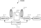
図2は、原稿固有の識別情報に対応して形成されたアモルファス磁歪素子の磁性タグを検知する検知装置1を概略的に示したブロック図であり、図3は、図2で示した検知装置1によって長さの異なるアモルファス磁歪素子で形成された磁性タグを検知した検知信号の一例を示す図である。
FIG. 2 is a block diagram schematically showing a
図2及び図3を参照しながらアモルファス磁歪素子の磁性タグを検知する方法について説明する。 A method for detecting the magnetic tag of the amorphous magnetostrictive element will be described with reference to FIGS.
図2に示すように、検知装置1は、所定周波数の交番磁界を生成する交番磁界生成部211と、交番磁界生成部211で生成された交番磁界を送信する送信コイル212と、送信コイル212を介して送信された交番磁界を受けて原稿200上に形成付与されたアモルファス磁歪素子の磁性タグ201(以下、「磁性タグ201」という。)の磁歪振動によって発する電磁波を受信する受信コイル213と、送信コイル212を介して所定周波数の交番磁界を一定時間送信後停止し、この交番磁界の送信停止期間中に磁性タグの磁歪振動によって発せられる電磁波を受信コイル213を介して受信するタイミング制御を行うタイミング制御部216と、受信コイル213で受信した信号に基づいて所定周波数の交番磁界と共振して磁歪振動した磁性タグの共振周波数を検出する信号検知部214及び周波数解析部215とで構成されている。
As illustrated in FIG. 2, the
原稿200は、検知装置1の送信コイル212と受信コイル213との間に配置され、交番磁界生成部211が周波数を低周波から高周波へ直線的に変化させた交番磁界を生成して送信コイル212を介して原稿200に対して送信する。
The
原稿200上に形成された磁性タグ201は、送信コイル212を介して送信された所定周波数の交番磁界によって共振して歪み、磁歪振動する。
The
なお、アモルファス磁歪素子が所定周波数の交番磁界を受けて磁歪振動する共振周波数は、アモルファス磁歪素子の材質や大きさ等によって定まるので、アモルファス磁歪素子は、アモルファス磁歪素子の材質や大きさ等に対応した固有の共振周波数の交番磁界を受けた時に最も振幅の大きな歪みを示して磁歪振動し、電磁波を発する。 Note that the resonance frequency at which the amorphous magnetostrictive element receives an alternating magnetic field of a predetermined frequency and magnetostrictively vibrates is determined by the material and size of the amorphous magnetostrictive element. Therefore, the amorphous magnetostrictive element corresponds to the material and size of the amorphous magnetostrictive element. When receiving an alternating magnetic field having a specific resonance frequency, it shows a distortion having the largest amplitude, vibrates magnetostrictively, and emits an electromagnetic wave.
このアモルファス磁歪素子の磁歪振動は、交番磁界の送信を停止しても、ある一定時間は収束しながら継続される。 The magnetostrictive vibration of the amorphous magnetostrictive element is continued while converging for a certain period of time even when transmission of the alternating magnetic field is stopped.
タイミング制御部216は、所定周波数の交番磁界を送信コイル212を介して一定期間送信後停止し、この交番磁界の送信停止期間中に磁性タグ201の磁歪振動により発する電磁波を受信コイル213を介して受信するようなタイミング制御を行う。
The timing control unit 216 stops the alternating magnetic field having a predetermined frequency after being transmitted through the transmission coil 212 for a certain period, and stops the electromagnetic wave generated by the magnetostrictive vibration of the
受信コイル213で受信した受信信号は、信号検知部214及び周波数解析部215において周波数解析され、受信コイルに流れる電流信号が最大の時の周波数を原稿200上に形成された磁性タグ201固有の共振周波数として検知される。
The reception signal received by the reception coil 213 is frequency-analyzed by the signal detection unit 214 and the frequency analysis unit 215, and the resonance characteristic of the
このように構成された検知装置1を用いて原稿200に対して所定周波数の交番磁界を送信し、原稿200から検出された磁性タグ201の磁歪振動による共振周波数を検知することにより原稿200に形成された磁性タグを特定することが可能となる。
Using the
アモルファス磁歪素子の磁歪振動による共振周波数は、前述したように、アモルファス磁歪素子の材質や大きさ等により定まり、検知したアモルファス磁歪素子の共振周波数から当該共振周波数に対応した材質や大きさ等を有するアモルファス磁歪素子の特定が可能となる。 As described above, the resonance frequency due to the magnetostrictive vibration of the amorphous magnetostrictive element is determined by the material and size of the amorphous magnetostrictive element, and has the material and size corresponding to the resonance frequency from the detected resonance frequency of the amorphous magnetostrictive element. The amorphous magnetostrictive element can be specified.
図3において、図3(a)から(c)は、長さの異なる細い薄箔の形状に形成されたアモルファス磁歪素子1M311(以下、「磁歪素子1M311」という。)、2M312(以下、「磁歪素子2M312」という。)、3M313(以下、「磁歪素子3M313」という。)がそれぞれ形成された原稿301、302、303を示す図であり、図3(d)から(f)は、各磁歪素子1M311、2M312、3M313が所定周波数の交番磁界を受けて磁歪振動した各磁歪素子固有の共振周波数特性を示す図である。 3, FIGS. 3A to 3C show amorphous magnetostrictive elements 1M311 (hereinafter referred to as “magnetostrictive element 1M311”) and 2M312 (hereinafter referred to as “magnetostrictive”) formed in the shape of thin thin foils having different lengths. 3D (hereinafter referred to as “element 2M312”) and 3M313 (hereinafter referred to as “magnetostrictive element 3M313”). FIG. 3D to FIG. It is a figure which shows the resonant frequency characteristic peculiar to each magnetostrictive element which 1M311, 2M312 and 3M313 received the alternating magnetic field of a predetermined frequency, and magnetostrictively vibrated.
各磁歪素子1M311、2M312、3M313は、前述したように、外部から磁界を与えると寸法変化を起こすような、いわゆる磁歪特性を有している。 As described above, each of the magnetostrictive elements 1M311, 2M312 and 3M313 has a so-called magnetostrictive characteristic that causes a dimensional change when a magnetic field is applied from the outside.
なお、図3(a)から(c)において、磁歪素子1M311、2M312、3M313の各数値1、2、3は、長さの異なる複数の磁歪素子を識別するために付したものであり、各磁歪素子1M311、2M312、3M313は、それぞれ組成、厚さ、幅が全て同一であり、長さが1M<2M<3Mの順に長いものとする。
In FIGS. 3A to 3C, the
図3(a)から(c)に示すように、長さの異なる各磁歪素子1M311、2M312、3M313が形成された各原稿301、302、303を図2で示した検知装置1の送信コイル212と受信コイル213との間にそれぞれ配置して交番磁界の周波数を例えば低周波から高周波へ順次変化させながら交番磁界を一定期間送信後停止し、この交番磁界の送信停止期間中に各原稿301、302、303に形成されたそれぞれの磁歪素子1M311、2M312、3M313が発する電磁波を受信して周波数解析すると、図3(d)から(f)に示すような各磁歪素子1M301、2M302、3M303固有の磁歪振動による共振周波数を波形信号D、E、Fとして検出することができる。
As shown in FIGS. 3A to 3C, the
なお、各波形信号D、E、Fは、各磁歪素子1M311、2M312、3M313が発する電磁波を受信し、受信コイルに流れる電流がピークとなった時の各周波数を周波数解析して得た結果の波形信号であり、図3(d)の波形信号Dは、磁歪素子1M311の共振周波数がf4であることを示し、図3(e)の波形信号Eは、磁歪素子2M312の共振周波数がf2、図3(f)の波形信号Fは、磁歪素子3M313の共振周波数がf1であることをそれぞれ示している。 The waveform signals D, E, and F are obtained as a result of frequency analysis of each frequency when the magnetostrictive elements 1M311, 2M312 and 3M313 receive electromagnetic waves and the current flowing through the receiving coil reaches a peak. A waveform signal D in FIG. 3D indicates that the resonance frequency of the magnetostrictive element 1M311 is f4, and a waveform signal E in FIG. 3E indicates that the resonance frequency of the magnetostrictive element 2M312 is f2. The waveform signal F in FIG. 3 (f) indicates that the resonance frequency of the magnetostrictive element 3M313 is f1.
このように、磁歪特性を有する各磁歪素子1M311、2M312、3M313で形成された磁性タグに対して低周波から高周波へ、もしくは高周波から低周波へ順次変化する交番磁界を与え、磁歪素子の磁歪振動によって発する電磁波を検出して共振周波数を検知することにより、検知した共振周波数に対応した磁歪素子を特定することが可能である。 In this way, an alternating magnetic field that sequentially changes from a low frequency to a high frequency or from a high frequency to a low frequency is applied to the magnetic tag formed by each of the magnetostrictive elements 1M311, 2M312 and 3M313 having magnetostrictive characteristics, and the magnetostrictive vibration of the magnetostrictive element. By detecting the electromagnetic wave emitted by the sensor and detecting the resonance frequency, it is possible to specify the magnetostrictive element corresponding to the detected resonance frequency.
なお、図3の例では、一つの磁歪素子で一つの磁性タグが形成された原稿の例を示したが、複数の磁歪素子を組合わせた磁性タグが形成された原稿であってもよい。 In the example of FIG. 3, an example of a document in which one magnetic tag is formed by one magnetostrictive element is shown, but a document in which a magnetic tag in which a plurality of magnetostrictive elements are combined may be formed.
前述の説明の如く、図3に示したアモルファス磁歪素子の磁性タグが所定周波数の交番磁界を受けて磁歪振動した際に検出される共振周波数の検出信号の一例は、いずれも原稿の用紙上にアモルファス磁歪素子の全面を接着形成された場合の例を示したものである。 As described above, examples of the detection signal of the resonance frequency detected when the magnetic tag of the amorphous magnetostrictive element shown in FIG. 3 receives an alternating magnetic field of a predetermined frequency and magnetostrictively vibrates are all on the original paper. An example in which the entire surface of an amorphous magnetostrictive element is formed by bonding is shown.
ところが、同一の組成(例えば、Fe−B−Si)、厚さ、幅、長さを有するアモルファス磁歪素子であってもアモルファス磁歪素子を用紙上に固定する固定部の面積(以下、「接着面積」という。)が異なると、接着面積に対応してアモルファス磁歪素子の磁歪振動による共振周波数が変化して検出される結果を得た。 However, even if the amorphous magnetostrictive element has the same composition (for example, Fe-B-Si), thickness, width, and length, the area of the fixing portion that fixes the amorphous magnetostrictive element on the sheet (hereinafter referred to as “bonding area”). ”), The resonance frequency due to the magnetostrictive vibration of the amorphous magnetostrictive element changes corresponding to the bonding area.
そこで、この発明に係わる磁性タグが付与された媒体の原稿には、磁性タグを形成する磁歪素子を原稿上に固定する接着面積を変化させて付与し、各原稿固有を識別可能とするように構成されている。 Therefore, the original of the medium to which the magnetic tag according to the present invention is attached is given by changing the adhesive area for fixing the magnetostrictive element forming the magnetic tag on the original so that each original can be identified. It is configured.
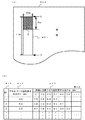
図4は、原稿上に固定された磁歪素子の接着面積に対応して検出された磁歪振動による共振周波数の検出結果を示した表である。 FIG. 4 is a table showing the detection result of the resonance frequency by the magnetostrictive vibration detected corresponding to the adhesion area of the magnetostrictive element fixed on the document.
図4(a)は、用紙上に接着固定されたアモルファス磁性素子の接着状態を示す図であり、図4(b)は、図4(a)で示したような用紙上に接着されて固定された磁歪素子の接着面積に対応した共振周波数の測定結果を示した表である。 FIG. 4A is a diagram showing the bonding state of the amorphous magnetic element bonded and fixed on the paper, and FIG. 4B is fixed by bonding on the paper as shown in FIG. 4A. It is the table | surface which showed the measurement result of the resonant frequency corresponding to the adhesion area of the made magnetostriction element.
図4(a)に示すように、この発明に係わる磁性タグが付与された媒体の原稿用紙400には、例えば厚さT、幅W、長さLのアモルファス磁歪素子401をアモルファス磁歪素子401の所定の片端Aから所定の片端Aとは対向する他の片端Cの方向へ長さBのW×Bの面積S(斜線を付した部分、以下、「接着面積S」という。)だけ用紙へ接着固定するように構成されており、アモルファス磁歪素子の長さLがそれぞれ30mm、40mm、50mmの各アモルファス磁歪素子の接着面積Sに対応した共振周波数の測定結果が図4(b)に示されている。 As shown in FIG. 4A, for example, an amorphous magnetostrictive element 401 having a thickness T, a width W, and a length L is placed on an original magnetostrictive element 401 having a magnetic tag according to the present invention. From the predetermined one end A to the other end C opposite to the predetermined one end A, a W × B area S of length B (a hatched portion, hereinafter referred to as “bonding area S”) is applied to the sheet. FIG. 4B shows the measurement result of the resonance frequency corresponding to the bonding area S of each amorphous magnetostrictive element which is configured to be bonded and fixed, and the length L of the amorphous magnetostrictive element is 30 mm, 40 mm and 50 mm, respectively. ing.
図4(b)に示した表40には、図4(a)で示したアモルファス磁歪素子401の厚さTが25μm、幅Wが7mm、長さLがそれぞれ30mm、40mm、50mmの各アモルファス磁歪素子に対して各アモルファス磁歪素子の所定の片端Aから所定の片端Aとは対向する他の片端Cの方向への長さBmmを変化させて各アモルファス磁歪素子の接着面積Sに対応した各アモルファス磁性素子の共振周波数を測定して得た結果が示してある。 In Table 40 shown in FIG. 4B, the amorphous magnetostrictive element 401 shown in FIG. 4A has a thickness T of 25 μm, a width W of 7 mm, and a length L of 30 mm, 40 mm, and 50 mm, respectively. The length corresponding to the bonding area S of each amorphous magnetostrictive element is changed by changing the length Bmm from the predetermined one end A of each amorphous magnetostrictive element to the other end C facing the predetermined one end A with respect to the magnetostrictive element. The results obtained by measuring the resonant frequency of the amorphous magnetic element are shown.
例えば、表40は、「NO.」欄411と、「アモルファス磁歪素子の長さL(mm)欄」412と、「用紙に接着させた磁性素子の長さB(mm)」欄413から構成されており、「用紙に接着させた磁性素子の長さB(mm)」欄413には、アモルファス磁歪素子の長さLが30mm、40mm、50mm・・・の各アモルファス磁歪素子の長さBがそれぞれ2mm、10mm、20mm、30mm、40mm、50mm・・・で形成される各アモルファス磁歪素子の接着面積Sに対応した共振周波数が示されている。 For example, the table 40 includes a “NO.” Column 411, a “amorphous magnetostrictive element length L (mm) column” 412, and a “magnetic element length B (mm) bonded to paper” column 413. In the “Length B (mm) of magnetic element bonded to paper” column 413, the length B of each amorphous magnetostrictive element having an amorphous magnetostrictive element length L of 30 mm, 40 mm, 50 mm,... , Resonance frequencies corresponding to the adhesion area S of each amorphous magnetostrictive element formed by 2 mm, 10 mm, 20 mm, 30 mm, 40 mm, 50 mm,.
なお、表40で示した長さLが30mm、40mm、50mm・・・の各アモルファス磁歪素子は、厚さTが25μm、幅Wが7mmであり、用紙に接着固定させた磁性素子の長さBが定まればBに対応したアモルファス磁歪素子の接着面積Sが7mm×Bmmで一義的に定まる。 Each of the amorphous magnetostrictive elements having a length L of 30 mm, 40 mm, 50 mm, etc. shown in Table 40 has a thickness T of 25 μm and a width W of 7 mm, and the length of the magnetic element adhered and fixed to the paper. If B is determined, the bonding area S of the amorphous magnetostrictive element corresponding to B is uniquely determined as 7 mm × Bmm.
表40によると、「NO.」欄411の「2」には、原稿用紙400上に長さLが40mmのアモルファス磁歪素子を所定の片端Aからの長さBを「2」mm、「10」mm、「20」mm、「30」mm、「40」mmだけ接着固定した各接着面積Sに対応したアモルファス磁歪素子の共振周波数がそれぞれ「58」kHz、「53」kHz、「50」kHz、「45」kHz、「41」kHzで検出されたことが示されている。 According to Table 40, “2” in the “NO.” Column 411 includes an amorphous magnetostrictive element having a length L of 40 mm on the original paper 400 and a length B from a predetermined one end A of “2” mm, “10”. ”Mm,“ 20 ”mm,“ 30 ”mm, and“ 40 ”mm, the resonant frequencies of the amorphous magnetostrictive elements corresponding to the bonding areas S are“ 58 ”kHz,“ 53 ”kHz, and“ 50 ”kHz, respectively. , “45” kHz, and “41” kHz.
なお、長さLが40mmのアモルファス磁歪素子に対して長さBを「40」mmだけ接着させた場合とは、アモルファス磁性素子の全面を原稿用紙400上に接着固定させたことを示している。 Note that the case where the length B is bonded by “40” mm to the amorphous magnetostrictive element having the length L of 40 mm indicates that the entire surface of the amorphous magnetic element is bonded and fixed on the document sheet 400. .
また、「NO.」欄411の「1」には、原稿用紙400上に長さLが30mmのアモルファス磁歪素子を所定の片端Aからの長さBを「2」mm、「10」mm、「20」mm、「30」mmだけ接着固定させた各接着面積Sに対応したアモルファス磁歪素子の共振周波数がそれぞれ「75」kHz、「65」kHz、「68」kHz、「57」kHzで検出されたことが示されており、「NO.」欄411の「3」には、原稿用紙400上に長さLが50mmのアモルファス磁歪素子を所定の片端Aからの長さBを「2」mm、「10」mm、「20」mm、「30」mm、「40」mm、「50」mmだけ接着固定した各接着面積Sに対応したアモルファス磁歪素子の共振周波数がそれぞれ「47」kHz、「38」kHz、「41」kHz、「42」kHz、「34」kHzで検出されたことが示されている。 Further, “1” in the “NO.” Column 411 includes an amorphous magnetostrictive element having a length L of 30 mm on the original paper 400 and a length B from a predetermined end A of “2” mm, “10” mm, The resonance frequency of the amorphous magnetostrictive element corresponding to each bonding area S, which is bonded and fixed by “20” mm and “30” mm, is detected at “75” kHz, “65” kHz, “68” kHz, and “57” kHz, respectively. In “3” of the “NO.” Column 411, an amorphous magnetostrictive element having a length L of 50 mm on the original paper 400 is set to a length B from a predetermined end A of “2”. mm, “10” mm, “20” mm, “30” mm, “40” mm, and “50” mm, the resonance frequency of the amorphous magnetostrictive element corresponding to each adhesion area S bonded and fixed is “47” kHz, "38" kHz, "41" Hz, "42" kHz, that is detected by the "34" kHz are shown.
このように、厚さT、幅W、長さLがそれぞれ同一のアモルファス磁歪素子に対して用紙上に接着固定させるアモルファス磁歪素子の接着面積Sを変化させることにより、接着面積Sに対応したアモルファス磁歪素子固有の共振周波数を検出することが可能となる。 As described above, the amorphous area corresponding to the adhesion area S is changed by changing the adhesion area S of the amorphous magnetostrictive element that is bonded and fixed on the paper to the amorphous magnetostrictive element having the same thickness T, width W, and length L. It becomes possible to detect the resonance frequency unique to the magnetostrictive element.
更に、長さLが異なる複数のアモルファス磁歪素子に対して用紙上に接着固定させるアモルファス磁歪素子の接着面積Sを変化させることによりモルファス磁歪素子の長さLと接着面積Sとに対応した固有の共振周波数を検出することができる。 Furthermore, by changing the bonding area S of the amorphous magnetostrictive element that is bonded and fixed on the sheet to a plurality of amorphous magnetostrictive elements having different lengths L, the unique length L corresponding to the length L and the bonding area S of the morphous magnetostrictive element is obtained. The resonance frequency can be detected.
したがって、長さLが異なる複数のアモルファス磁歪素子を用紙上に接着固定するアモルファス磁歪素子の接着面積Sを変化させて形成し、アモルファス磁歪素子の長さLと接着面積Sに対応した固有の共振周波数を予め測定して記憶することにより、検知した共振周波数に対応したアモルファス磁歪素子の接着面積Sとアモルファス磁歪素子の長さLを特定することができる。 Therefore, a plurality of amorphous magnetostrictive elements having different lengths L are formed by changing the adhesive area S of the amorphous magnetostrictive element for adhering and fixing on the paper, and the inherent resonance corresponding to the length L and the adhesive area S of the amorphous magnetostrictive element. By measuring and storing the frequency in advance, the adhesive area S of the amorphous magnetostrictive element and the length L of the amorphous magnetostrictive element corresponding to the detected resonance frequency can be specified.
すなわち、同じ長さのアモルファス磁歪素子であっても用紙上に接着固定させるアモルファス磁歪素子の接着面積によって共振周波数が異なり、更に、長さの異なるアモルファス磁歪素子に対する接着面積に対応してアモルファス磁歪素子の共振周波数が異なるので、これらを対応付けたデータを予め作成し、参照することにより、より多くの情報が表現されて付加された磁性タグの情報を読み取ることが可能となる。 That is, even if the amorphous magnetostrictive element has the same length, the resonance frequency varies depending on the adhesive area of the amorphous magnetostrictive element that is bonded and fixed on the paper, and the amorphous magnetostrictive element corresponds to the adhesive area to the amorphous magnetostrictive element having a different length. Therefore, it is possible to read the information of the magnetic tag added with more information expressed by creating and referring to data in which these are associated in advance.
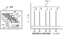
図5は、封筒4内に収納された、この発明に係わる磁性タグが付与された媒体である複数種類の原稿で一セットを構成する各原稿にそれぞれ形成された磁性タグの一例を示す図であり、図6は、図5で示した磁性タグが形成された各原稿が収納された原稿に対して所定周波数の交番磁界を与えることにより検出された各磁性タグの磁歪振動による共振周波数パターンを示す図である。
FIG. 5 is a view showing an example of a magnetic tag formed on each original constituting a set of a plurality of types of originals that are stored in an
図5に示すように、第一原稿51には磁性タグ1L511、第二原稿52には磁性タグ2L521、第三原稿53には磁性タグ3L531、第四原稿54には磁性タグ4L541、第五原稿55には磁性タグ5L551がそれぞれ形成されており、各磁性タグは図4(b)の表40、「NO.」欄411の「2」で示した厚さTが25μm、幅Wが7mm、長さLが40mmのアモルファス磁歪素子で構成され、各原稿用紙上に各磁性タグのアモルファス磁歪素子を接着固定する接着面積が異なるように形成されている。 As shown in FIG. 5, the first original 51 has a magnetic tag 1L511, the second original 52 has a magnetic tag 2L521, the third original 53 has a magnetic tag 3L531, the fourth original 54 has a magnetic tag 4L541, and a fifth original. 55, magnetic tags 5L551 are respectively formed. Each magnetic tag has a thickness T of 25 μm, a width W of 7 mm, as shown in Table 40 of FIG. 4B, “2” in the “NO.” Column 411, It is composed of an amorphous magnetostrictive element having a length L of 40 mm, and is formed so that the adhesive areas for adhering and fixing the amorphous magnetostrictive element of each magnetic tag on each original sheet are different.
例えば、第一原稿51にはアモルファス磁歪素子をアモルファス磁歪素子の所定の片端Aから長さBを2mmだけ接着固定した磁性タグ1L511が形成されており、第二原稿52、第三原稿53、第四原稿54、第五原稿55にはそれぞれ各原稿に形成されたアモルファス磁歪素子の所定の片端Aから長さBがそれぞれ10mm、20mm、30mm、40mm(全面)だけ接着固定した磁性タグ2L521、3L531、4L541、5L551がそれぞれ形成されている。
For example, the first original 51 is formed with a magnetic tag 1L511 in which an amorphous magnetostrictive element is bonded and fixed to a length B of 2 mm from a predetermined end A of the amorphous magnetostrictive element. Magnetic tags 2L521, 3L531 having a length B of 10 mm, 20 mm, 30 mm, and 40 mm (entire surface) from predetermined one end A of the amorphous magnetostrictive element formed on each of the four
このように形成された磁性タグ1L511、2L521、3L531、4L541、5L551が付与された各原稿51、52、53、54、55が収納された封筒4に対して封筒4の外部から周波数を低周波から高周波へ、もしくは高周波から低周波へ直線的に変化させた交番磁界を与えると、各原稿に形成された磁性タグが交番磁界の周波数に共振して磁歪振動する。
The frequency from the outside of the
この各磁性タグの所定周波数の交番磁界に共振した磁歪振動は、各磁性タグが最も振幅の大きな歪みを示し振動するので、各磁性タグの磁歪振動によって発せられる所定強度の電磁波を検出してみると、図6に示すような共振周波数パターン601が検出される。
The magnetostrictive vibration resonating with an alternating magnetic field of a predetermined frequency of each magnetic tag causes each magnetic tag to vibrate with the largest amplitude distortion. Therefore, an electromagnetic wave having a predetermined intensity generated by the magnetostrictive vibration of each magnetic tag is detected. Then, a
共振周波数パターン601には、各磁性タグ1L511、2L521、3L531、4L541、5L551のそれぞれ固有の共振周波数を示す波形信号G、H、I、J、Kが検出されており、波形信号Gは、磁歪素子1L511の共振周波数を示し、波形信号Hは、磁歪素子2L521の共振周波数、波形信号Iは、磁歪素子3L531の共振周波数、波形信号Jは、磁歪素子4L541の共振周波数、波形信号Kは、磁歪素子5L551の共振周波数を示している。
In the
そこで、各磁性タグ1L511、2L521、3L531、4L541、5L551がそれぞれ形成された第一原稿51、第二原稿52、第三原稿53、第四原稿54、第五原稿55を重ねて封筒4の中に入れて封印後、この封筒4内の各原稿を開封することなく封筒4の外部から非接触で封筒4内に収納された原稿を検知確認する方法について説明する。
Therefore, the
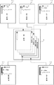
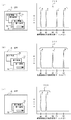
図7は、図5で示した第一原稿51、第二原稿52、第三原稿53、第四原稿54、第五原稿55の原稿で一セットを構成し、この一セットを構成する各原稿を封筒4内に収納して発送する場合において、いくつかの原稿を封筒4内に入れ忘れた場合の封筒4から、検出された共振周波数パターンを示す図である。
FIG. 7 shows a set of the
図7(a)は、封筒4内に第三原稿53を入れ忘れた状態の共振周波数パターンを示す図であり、図7(b)は、封筒4内に第二原稿52及び第四原稿54を入れ忘れた状態の共振周波数パターンを示す図、図7(c)は、封筒4内に第三原稿53、第四原稿54及び第五原稿55を入れ忘れた状態の共振周波数パターンを示す図である。
FIG. 7A is a diagram showing a resonance frequency pattern in a state where the
これらの共振周波数パターンに基づいて封筒4内に収納されている原稿の種類を確認し、入れ忘れの原稿がないか否かを判別することができる。
Based on these resonance frequency patterns, the type of the document stored in the
例えば、図7(a)に示すように、第三原稿53を入れ忘れた状態の封筒4に対して周波数を低周波から高周波へ、もしくは高周波から低周波へ直線的に変化させた交番磁界を与えると、封筒4内に収納された第一原稿51、第二原稿52、第四原稿54、第五原稿55に形成されたそれぞれの磁性タグ1L511、2L521、4L541、5L551がそれぞれの固有の共振周波数の交番磁界を受けて磁歪振動して電磁波を発し、検知装置1が各磁性タグ固有の磁歪振動の共振周波数を検出して図7(a)に示すような共振周波数パターン701を検知する。
For example, as shown in FIG. 7A, an alternating magnetic field in which the frequency is linearly changed from a low frequency to a high frequency or from a high frequency to a low frequency is applied to the
共振周波数パターン701には、波形信号G、H、J、Kが検出されており、図6で示した共振周波数パターン601と比較してみると、共振周波数パターン701には第三原稿53に形成された磁性タグ3L531の共振周波数である波形信号Iが検出されていないことが分かる。
Waveform signals G, H, J, and K are detected in the
また、図7(b)に示すように、第二原稿52及び第四原稿54を入れ忘れた状態の封筒4に対して周波数を低周波から高周波へ、もしくは高周波から低周波へ直線的に変化させた交番磁界を与えると、封筒4内に収納された第一原稿51、第三原稿53及び第五原稿55に形成されたそれぞれの磁性タグ1L511、3L531、5L551がそれぞれの固有の共振周波数の交番磁界を受けて磁歪振動して電磁波を発し、検知装置1が各磁性タグ固有の磁歪振動の共振周波数を検出して図7(b)に示すような共振周波数パターン702を検知する。
Further, as shown in FIG. 7B, the frequency is linearly changed from a low frequency to a high frequency or from a high frequency to a low frequency with respect to the
共振周波数パターン703には、波形信号G、I、Jが検出されており、図6で示した共振周波数パターン601と比較してみると、共振周波数パターン702には第二原稿52及び第四原稿54にそれぞれ形成された磁性タグ2L521及び3L531の共振周波数を示す波形信号H、Kが検出されていないことが分かる。
Waveform signals G, I, and J are detected in the resonance frequency pattern 703. Compared with the
また、図7(c)に示すように、第三原稿53、第四原稿54及び第五原稿55を入れ忘れた状態の封筒4に対して周波数を低周波から高周波へ、もしくは高周波から低周波へ直線的に変化させた交番磁界を与えると、封筒4内に収納された第一原稿51及び第二原稿52に形成されたそれぞれの磁性タグ1L511、2L521がそれぞれの固有の共振周波数の交番磁界を受けて磁歪振動して電磁波を発し、検知装置1が各磁性タグ固有の磁歪振動の共振周波数を検出して図7(c)に示すような共振周波数パターン703を検知する。
Further, as shown in FIG. 7C, the frequency is changed from a low frequency to a high frequency or from a high frequency to a low frequency with respect to the
共振周波数パターン703には、波形信号G、Hが検出されており、図6で示した共振周波数パターン601と比較してみると、共振周波数パターン703には第二原稿52、第三原稿53、第四原稿54及び第五原稿55にそれぞれ形成された磁性タグ2L521、3L531、4L541及び5L551の共振周波数を示す波形信号I、J、Kが検出されていないことが分かる。
Waveform signals G and H are detected in the resonance frequency pattern 703. Compared with the
このように、検知装置1が封筒4に対して周波数を低周波から高周波へ、もしくは高周波から低周波へ直線的に変化させた交番磁界を送信し、送信した各周波数の交番磁界によって封筒4内に収納された各原稿の磁性タグの磁歪振動による電磁波を検出し、各磁性タグのアモルファス磁歪素子が原稿上に接着固定された接着面積に対応した磁歪振動による共振周波数を検知することにより、封筒4内に収納された原稿の種類を封筒4の外部から非接触で原稿4を開封することなく検知確認することができる。
In this way, the
なお、一セットを構成する第一原稿51、第二原稿52、第三原稿53、第四原稿54、第五原稿55の各原稿に形成された各磁性タグ1L511、2L521、3L531、4L541、5L551それぞれ固有の磁歪振動の共振周波数は、予め検知装置1で検出して記憶管理されているものとする。
Note that the magnetic tags 1L511, 2L521, 3L531, 4L541, 5L551 formed on the originals of the first original 51, the second original 52, the third original 53, the fourth original 54, and the fifth original 55 constituting one set. It is assumed that the resonance frequency of each inherent magnetostrictive vibration is detected and stored and managed by the
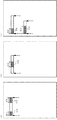
以上の説明においては、各原稿固有を識別可能とする識別情報がアモルファス磁歪素子の所定の片端Aから所定の片端Aとは対向する他の片端Cの方向へ長さBのW×Bの接着面積Sだけ用紙へ接着固定された構成の例を示したが、図8に示すようなアモルファス磁歪素子をアモルファス磁歪素子の両端A及びCからそれぞれ所定の長さB(1)、B(2)で形成される接着面積S(1)、S(2)の部分(図8(a)の斜線部分を参照)のみを原稿上に接着固定して形成された構成にしてもよく、また、アモルファス磁歪素子の片端A及びC以外の任意の位置から所定の長さB(3)で形成される接着面積S(3)の部分(図8(b)の斜線部分を参照)のみを原稿上に接着固定して形成された構成にしてもよい。 In the above description, the identification information enabling identification of each document is the W × B adhesive length B from the predetermined one end A of the amorphous magnetostrictive element to the other one end C facing the predetermined one end A. Although an example of a configuration in which the area S is adhesively fixed to the paper has been shown, an amorphous magnetostrictive element as shown in FIG. 8 has a predetermined length B (1), B (2) from both ends A and C of the amorphous magnetostrictive element, respectively. May be formed by bonding and fixing only the portions of the bonding areas S (1) and S (2) (see the hatched portion in FIG. 8A) formed on the document. Only the portion of the adhesive area S (3) formed by a predetermined length B (3) from any position other than one end A and C of the magnetostrictive element (see the hatched portion in FIG. 8B) is placed on the document. It may be configured to be bonded and fixed.
また、アモルファス磁歪素子の厚さ、幅、長さがそれぞれ異なる複数のアモルファス磁歪素子と各アモルファス磁歪素子を原稿へ接着させる接着面積S(4)、S(5)(図8(c)の斜線部分を参照)とを組合わせて原稿上へ接着固定して形成した構成でもよい。 Also, a plurality of amorphous magnetostrictive elements having different thicknesses, widths, and lengths of the amorphous magnetostrictive elements, and adhesive areas S (4) and S (5) for adhering the amorphous magnetostrictive elements to the original (shaded lines in FIG. 8C) (Refer to the portion) may be combined and fixed on the original.
さて、ここで、この発明に係わる磁性タグが付与された媒体を作成する方法について簡単に説明する。 Now, a method for producing a medium with a magnetic tag according to the present invention will be briefly described.
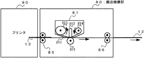
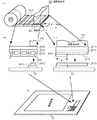
図9は、付加情報が付与された本発明に係わる媒体を作成するための付加情報付与装置の一例の構成を示すブロック図であり、図10は、付加情報付与装置900のうちの搬送機構部80の部分の構造を概略的に示した図である。 FIG. 9 is a block diagram showing a configuration of an example of an additional information adding device for creating a medium according to the present invention to which additional information is added, and FIG. 10 is a transport mechanism section of the additional information adding device 900. It is the figure which showed the structure of the part of 80 roughly.
なお、図9及び図10において、図9に示した搬送機構部80を平面図とし、図10に示した図を側面図として示してある。
図9及び図10において、付加情報付与装置900(一点鎖線で囲まれた部分)は、画像形成装置であるプリンタ2の用紙搬出側に取り付けられ、プリンタ2によって画像情報が印刷されて排紙された原稿12を取り込み、その原稿12に原稿12固有を識別可能とする識別情報をアモルファス磁歪素子の磁性タグ830で形成付与するように構成されている。
9 and 10, the transport mechanism 80 shown in FIG. 9 is a plan view, and the view shown in FIG. 10 is a side view.
9 and 10, an additional information adding device 900 (a portion surrounded by a one-dot chain line) is attached to the paper carry-out side of the
また、原稿12上に形成付与するアモルファス磁歪素子の磁性タグ830は、原稿12固有の識別情報に対応してアモルファス磁歪素子を原稿12上に形成付与する際に、原稿12上に接着固定させるアモルファス磁歪素子の接着面積を変化させて形成付与する。
The magnetic tag 830 of the amorphous magnetostrictive element formed and applied on the
付加情報付与装置900には、プリンタ2から排紙された原稿12を搬送する搬送機構部80と、搬送機構部80の駆動制御や原稿12上に形成する原稿12固有の識別情報に対応した磁性タグ11を形成するための制御等を行う制御回路部70から構成されている。
The additional information adding device 900 includes a transport mechanism 80 that transports the
搬送機構部80の一対の用紙送りローラ85は、プリンタ2の用紙搬出口の対向の位置に設けられ、プリンタ2から排紙された原稿12を搬送機構部80の内部に取り込み、取り込んだ原稿12を一対の用紙搬出ローラ86が付加情報付与装置900の外部へ搬出する。
The pair of paper feed rollers 85 of the transport mechanism unit 80 is provided at a position opposite to the paper carry-out port of the
図10に示すように、各ローラ85、86の間には、磁歪素子転写装置81(図9においては一点鎖線で囲まれた部分)が配置されており、磁歪素子転写装置81の発熱抵抗体812の対向する位置には、ガイド用ローラ871が設置されている。
As shown in FIG. 10, a magnetostrictive element transfer device 81 (a portion surrounded by an alternate long and short dash line in FIG. 9) is disposed between the
プリンタ2から排紙された原稿12は、一対の用紙送りローラ85と、磁歪素子転写装置81とガイド用ローラ871との間と、一対の用紙搬出ローラ86とを通過して搬送機構部80から搬出される。
The original 12 discharged from the
搬送機構部80の磁歪素子転写装置81には、アモルファス磁歪素子を原稿12上に接着固定させる際に、アモルファス磁歪素子の所望の面積だけ接着可能なように構成した熱転写シート811が十分に巻き付けられたシート送りローラ813と、熱転写シート811の端部に取り付けられたシート巻取ローラ814を備えている。
The magnetostrictive element transfer device 81 of the transport mechanism 80 is sufficiently wound with a
磁歪素子転写装置81は、アモルファス磁歪素子の厚さ、幅、長さ及び原稿12上にアモルファス磁歪素子を接着させる接着面積に対応した種類の熱転写シートが収納された磁歪素子転写装置と変更することにより、所望の大きさのアモルファス磁歪素子を所望の接着面積で原稿上に接着固定することが可能である。 The magnetostrictive element transfer device 81 is changed to a magnetostrictive element transfer device in which a thermal transfer sheet of a type corresponding to the thickness, width, and length of the amorphous magnetostrictive element and the bonding area for bonding the amorphous magnetostrictive element on the original 12 is accommodated. Thus, it is possible to bond and fix an amorphous magnetostrictive element of a desired size on a document with a desired bonding area.
例えば、図5で示したような第三原稿53に形成付加された磁性タグ3L531を原稿12上に形成する場合は、厚さTが25μm、幅Wが7mm、長さLが40mmのアモルファス磁歪素子をアモルファス磁歪素子の片端Aから長さBを20mmだけ原稿12上に接着可能とするように加工した熱転写シートが収納された磁歪素子転写装置を配置することにより磁性タグ3L531と同一の磁性タグを原稿12上に形成付与することができる。
For example, when the magnetic tag 3L531 formed and added to the third original 53 as shown in FIG. 5 is formed on the original 12, the amorphous magnetostriction having a thickness T of 25 μm, a width W of 7 mm, and a length L of 40 mm. The same magnetic tag as the magnetic tag 3L531 is provided by disposing a magnetostrictive element transfer device containing a thermal transfer sheet in which the element is bonded to the original 12 by 20 mm in length B from one end A of the amorphous magnetostrictive element. Can be formed on the
プリンタ2から排紙された原稿12は、一対の用紙送りローラ85と、磁歪素子転写装置81とガイド用ローラ871との間と、一対の用紙搬出ローラ86とを通過して搬送機構部80から搬出される。
The original 12 discharged from the
熱転写シート811は、制御回路部70による磁歪素子転写装置81の駆動制御によりシート送りローラ813から送り出され、シート巻取ローラ814により巻き取られる。 熱転写シート811は、制御回路部70による制御に基づいて発熱抵抗体812とガイド用ローラ871との間を原稿12と共に通過するように構成されている。
The
なお、磁歪素子転写装置81は、ガイド用ローラ871の軸方向に搬送機構部80の内部を摺動可能に取り付けられており、熱転写シート811に含まれるアモルファス磁歪素子を原稿12上の所望位置に熱転写可能なように構成されている。
The magnetostrictive element transfer device 81 is slidably mounted inside the transport mechanism 80 in the axial direction of the
付加情報付与装置900の制御回路部70は、情報入力部71と、搬送制御部72と磁性タグ形成部73を備えている。
The
情報入力部71は、プリンタ2により印刷された画像情報をプリンタ2から取得する。
The information input unit 71 acquires image information printed by the
搬送制御部72は、搬送機構部80の駆動制御を行うことでプリンタ2から排紙された原稿12を搬送する。
The
磁性タグ形成部73は、搬送制御部12と連係して熱転写シート811が収納された磁歪素子転写装置81のシート送りローラ813及びシート巻取ローラ814の動作を制御する。
The magnetic
そして熱転写シート811の搬送制御を行いながら、磁歪素子転写装置81の発熱抵抗体812を発熱させて熱転写シート811の一部を溶解して原稿12上にアモルファス磁歪素子の所定の接着面積だけ熱転写して接着固定する。
Then, while controlling the conveyance of the
このように原稿12の識別情報に対応したアモルファス磁歪素子の接着面積を原稿12上に熱転写して接着固定する。
In this way, the bonding area of the amorphous magnetostrictive element corresponding to the identification information of the
図11は、磁歪素子転写装置81に収納されている熱転写シート811の構成を示す図である。
FIG. 11 is a diagram showing a configuration of the
図11(a)は、磁歪素子転写装置81に収納された熱転写シート811の基本構成を示した斜視図であり、図11(b)及び図11(c)は、図11(a)で示した熱転写シート811の斜視図を所定方向から見た場合の熱転写シート811の特徴的な構成の部分を拡大して示した図である。
FIG. 11A is a perspective view showing the basic configuration of the
なお、図11においては、説明の便宜上、図5で示した第三原稿53に形成付加された磁性タグ3L531を例に示したものである。
In FIG. 11, for convenience of explanation, the magnetic tag 3L531 formed and added to the
図11に示すように、熱転写シート811は、シート基板8110と、熱溶融材で構成された熱溶融層8111と、厚さTが25μm、幅Wが7mm、長さLが40mmのアモルファス磁歪素子8113と粘着材で構成された粘着層8112の3層で構成されている。
As shown in FIG. 11, a
粘着層811は、アモルファス磁歪素子8113を原稿12に接着固定する際に、アモルファス磁歪素子8113の片端Aからの長さBが20mmだけ接着可能なように接着材が付加されている(図11(c)参照)。
An adhesive is added to the
熱溶融層8111及び粘着層8112は、熱転写シート811の送り出し方向(図11(a)中の矢印820)とは直交する方向に所定間隔に分割されている。
The heat-melting layer 8111 and the
原稿12へ熱転写シート811を熱転写する場合は、発熱抵抗体812により行われるので、発熱抵抗体812の幅に合わせて予め熱転写シート811を分割しておくことが望ましい。
When the
分割された熱転写シート811の各領域、例えば811a、811bにはアモルファス磁歪素子8113が含まれる。
Each region of the divided
また、シート基板8110としてはアセトートフィルムを、また粘着材としてはアクリル樹脂系粘着材を用いることができる。 Further, an acetoate film can be used as the sheet substrate 8110, and an acrylic resin adhesive can be used as the adhesive.
図12は、図11で示した熱転写シート811を原稿上に熱転写する基本的な処理を説明するための説明図である。
FIG. 12 is an explanatory diagram for explaining a basic process for thermally transferring the
図12(a)は、発熱抵抗体812が発熱して熱転写シート811を原稿12上に熱転写する様子を示した斜視図であり、図12(b)及び図12(c)は、図12(a)で示した熱転写シート811の斜視図を所定方向から見た場合の熱転写シート811の様子を示した図、図12(d)は、原稿12上に形成されたアモルファス磁歪素子8113の磁性タグを示す図である。
12A is a perspective view showing a state in which the
図12を参照しながら熱転写シートのアモルファス磁性素子を原稿12上に熱転写する基本的な処理について簡単に説明する。
A basic process for thermally transferring the amorphous magnetic element of the thermal transfer sheet onto the
プリンタ2から画像情報が印刷された原稿12が排紙され、付加情報付与装置900の搬送機構部80に搬入されると、用紙送りローラ85によって原稿12が磁歪素子転写装置81の発熱抵抗体812の直下へ搬送される。
When the
磁性タグ形成部73は、原稿12上に印刷された画像情報に対応して原稿12上の所定の位置、例えば画像情報が印刷されていない部分等の位置へ磁性タグが形成可能なように磁歪素子転写装置81を移動させ、磁歪素子転写装置81の発熱抵抗体812を必要に応じて発熱させる。
The magnetic
この発熱抵抗体812の発熱により発熱時点において図12(a)乃至(c)に示すような発熱抵抗体812の位置にあった熱溶融層8111は溶融し、その溶融した熱溶融層8111に対応する位置の粘着層8112がはがれ、図12(d)に示すように、並行して搬送している原稿12上に粘着する。
Due to the heat generated by the
なお、発熱抵抗体812の発熱時点においては、熱転写シート811と原稿12の各搬送速度が同速に制御されている。
Note that when the
このようにして熱転写シート811に含まれるアモルファス磁性素子813が原稿12上に熱転写され磁性タグ3L531が原稿12上に形成付与される。
In this way, the amorphous
1 検知装置
2 コンピュータ
3 搬送機構装置
4 封筒
12、200、301、302、303、400 原稿
30 搬送用ベルト
31 ゲート
32 ゲート制御装置
33 封筒配送箱
34 封筒回収箱
35 配送用ベルトの搬送方向
51 第一原稿
52 第二原稿
53 第三原稿
54 第四原稿
55 第五原稿
70 制御回路部
71 情報入力部
72 搬送制御部
73 磁性タグ形成部
80 搬送機構部
81 磁性素子転写装置
85 用紙送りローラ
86 用紙搬出ローラ
90 プリンタ
201、401 アモルファス磁性タグ
211 交番磁界生成部
212 送信コイル
213 受信コイル
214 信号検知部
215 周波数解析部
216 タイミング制御部
311 アモルファス磁性タグ(1M)
312 アモルファス磁性タグ(2M)
313 アモルファス磁性タグ(3M)
511 アモルファス磁性タグ(1L)
521 アモルファス磁性タグ(2L)
531 アモルファス磁性タグ(3L)
541 アモルファス磁性タグ(4L)
551 アモルファス磁性タグ(5L)
811 熱転写シート
812 発熱抵抗体
813 シート送りローラ
814 シート巻取ローラ
871 ガイド用ローラ
8110 シート基板
8111 熱溶融層
8112 粘着層とアモルファス磁性素子
8113 アモルファス磁性素子
DESCRIPTION OF
312 Amorphous magnetic tag (2M)
313 Amorphous magnetic tag (3M)
511 Amorphous magnetic tag (1L)
521 Amorphous magnetic tag (2L)
531 Amorphous Magnetic Tag (3L)
541 Amorphous Magnetic Tag (4L)
551 Amorphous magnetic tag (5L)
811
Claims (10)
前記磁性タグを形成する磁歪素子は、少なくとも一部が前記媒体上に固定され、
前記磁歪素子を媒体に固定する固定部の面積を異ならせることにより前記所定の交番磁界中における前記磁歪素子の共振振動周波数を変化させる
ことを特徴とする媒体識別方法。 In a medium identification method using a magnetic tag, wherein a magnetic tag comprising at least one magnetostrictive element is provided on a medium and tag information of the magnetic tag is read based on a resonance vibration frequency of the magnetostrictive element in a predetermined alternating magnetic field.
The magnetostrictive element forming the magnetic tag is at least partially fixed on the medium,
A medium identification method, comprising: changing a resonance vibration frequency of the magnetostrictive element in the predetermined alternating magnetic field by changing an area of a fixing portion for fixing the magnetostrictive element to the medium.
複数の磁歪素子からなり、
前記タグ情報は、
前記複数の磁歪素子の共振振動の周波数パターンに基づき読み取られる
ことを特徴とする請求項1記載の媒体識別方法。 The magnetostrictive element is
Consisting of multiple magnetostrictive elements,
The tag information is
The medium identification method according to claim 1, wherein reading is performed based on a frequency pattern of resonance vibration of the plurality of magnetostrictive elements.
形状が同じで該磁歪素子の固定部の面積がそれぞれ異なる
ことを特徴とする請求項2記載の媒体識別方法。 The plurality of magnetostrictive elements are:
The medium identification method according to claim 2, wherein the shape is the same and the area of the fixed portion of the magnetostrictive element is different.
少なくとも1つが形状が異なること
を特徴とする請求項2記載の媒体識別方法。 The plurality of magnetostrictive elements are:
The medium identification method according to claim 2, wherein at least one has a different shape.
前記複数の磁歪素子の共振振動の周波数パターンの一部に基づき読み取られる
ことを特徴とする請求項1乃至4のいずれかに記載の媒体識別方法。 The tag information is
The medium identification method according to claim 1, wherein the medium identification method is read based on a part of a frequency pattern of resonance vibration of the plurality of magnetostrictive elements.
前記磁性タグを形成する磁歪素子は、少なくとも一部が前記媒体上に固定され、
前記磁歪素子を媒体に固定する固定部の面積を異ならせることにより前記所定の交番磁界中における前記磁歪素子の共振振動周波数を変化させる
ことを特徴とする磁性タグが付与された媒体。 In a medium provided with a magnetic tag comprising at least one magnetostrictive element, and provided with a magnetic tag identified by tag information of the magnetic tag read based on a resonance vibration frequency of the magnetostrictive element in a predetermined alternating magnetic field,
The magnetostrictive element forming the magnetic tag is at least partially fixed on the medium,
A medium provided with a magnetic tag, wherein a resonance vibration frequency of the magnetostrictive element in the predetermined alternating magnetic field is changed by changing an area of a fixing portion for fixing the magnetostrictive element to the medium.
複数の磁歪素子からなり、
前記タグ情報は、
前記複数の磁歪素子の共振振動の周波数パターンに基づき読み取られる
ことを特徴とする請求項6記載の磁性タグが付与された媒体。 The magnetostrictive element is
Consisting of multiple magnetostrictive elements,
The tag information is
The medium provided with the magnetic tag according to claim 6, wherein the medium is read based on a frequency pattern of resonance vibration of the plurality of magnetostrictive elements.
形状が同じで該磁歪素子の固定部の面積がそれぞれ異なる
ことを特徴とする請求項7記載の磁性タグが付与された媒体。 The plurality of magnetostrictive elements are:
The medium provided with the magnetic tag according to claim 7, wherein the medium has the same shape and the areas of the fixed portions of the magnetostrictive element are different from each other.
少なくとも1つが形状が異なること
を特徴とする請求項7記載の磁性タグが付与された媒体。 The plurality of magnetostrictive elements are:
The medium provided with the magnetic tag according to claim 7, wherein at least one has a different shape.
前記複数の磁歪素子の共振振動の周波数パターンの一部に基づき読み取られる
ことを特徴とする請求項6乃至9のいずれかに記載の磁性タグが付与された媒体。 The tag information is
The medium provided with the magnetic tag according to claim 6, wherein the medium is read based on a part of a frequency pattern of resonance vibration of the plurality of magnetostrictive elements.
Priority Applications (1)
| Application Number | Priority Date | Filing Date | Title |
|---|---|---|---|
| JP2004015765A JP4525086B2 (en) | 2004-01-23 | 2004-01-23 | Medium identification method using magnetic tag and medium provided with magnetic tag |
Applications Claiming Priority (1)
| Application Number | Priority Date | Filing Date | Title |
|---|---|---|---|
| JP2004015765A JP4525086B2 (en) | 2004-01-23 | 2004-01-23 | Medium identification method using magnetic tag and medium provided with magnetic tag |
Publications (2)
| Publication Number | Publication Date |
|---|---|
| JP2005209010A true JP2005209010A (en) | 2005-08-04 |
| JP4525086B2 JP4525086B2 (en) | 2010-08-18 |
Family
ID=34901138
Family Applications (1)
| Application Number | Title | Priority Date | Filing Date |
|---|---|---|---|
| JP2004015765A Expired - Fee Related JP4525086B2 (en) | 2004-01-23 | 2004-01-23 | Medium identification method using magnetic tag and medium provided with magnetic tag |
Country Status (1)
| Country | Link |
|---|---|
| JP (1) | JP4525086B2 (en) |
Cited By (1)
| Publication number | Priority date | Publication date | Assignee | Title |
|---|---|---|---|---|
| JP2009113349A (en) * | 2007-11-07 | 2009-05-28 | Toppan Forms Co Ltd | Form body with magnetic mark |
Citations (5)
| Publication number | Priority date | Publication date | Assignee | Title |
|---|---|---|---|---|
| JPH04157588A (en) * | 1990-10-22 | 1992-05-29 | Fuji Electric Co Ltd | Magnetic marker for object identification |
| JPH07272132A (en) * | 1994-04-01 | 1995-10-20 | Dainippon Ink & Chem Inc | Magnetic marker |
| JPH08249431A (en) * | 1994-11-23 | 1996-09-27 | Internatl Business Mach Corp <Ibm> | Magnetic tag executing acoustic or magnetic inquiry |
| JPH08293012A (en) * | 1995-04-21 | 1996-11-05 | Toppan Printing Co Ltd | Information recording medium |
| JPH0992519A (en) * | 1995-09-26 | 1997-04-04 | Hitachi Metals Ltd | Magnetic element and its manufacturing method |
-
2004
- 2004-01-23 JP JP2004015765A patent/JP4525086B2/en not_active Expired - Fee Related
Patent Citations (5)
| Publication number | Priority date | Publication date | Assignee | Title |
|---|---|---|---|---|
| JPH04157588A (en) * | 1990-10-22 | 1992-05-29 | Fuji Electric Co Ltd | Magnetic marker for object identification |
| JPH07272132A (en) * | 1994-04-01 | 1995-10-20 | Dainippon Ink & Chem Inc | Magnetic marker |
| JPH08249431A (en) * | 1994-11-23 | 1996-09-27 | Internatl Business Mach Corp <Ibm> | Magnetic tag executing acoustic or magnetic inquiry |
| JPH08293012A (en) * | 1995-04-21 | 1996-11-05 | Toppan Printing Co Ltd | Information recording medium |
| JPH0992519A (en) * | 1995-09-26 | 1997-04-04 | Hitachi Metals Ltd | Magnetic element and its manufacturing method |
Cited By (1)
| Publication number | Priority date | Publication date | Assignee | Title |
|---|---|---|---|---|
| JP2009113349A (en) * | 2007-11-07 | 2009-05-28 | Toppan Forms Co Ltd | Form body with magnetic mark |
Also Published As
| Publication number | Publication date |
|---|---|
| JP4525086B2 (en) | 2010-08-18 |
Similar Documents
| Publication | Publication Date | Title |
|---|---|---|
| JP4725261B2 (en) | RFID tag inspection method | |
| US7245401B2 (en) | Device and method for recording additional information on printing medium, and image forming apparatus | |
| CN1784690B (en) | Box for making wireless identification tags mounted on its making device | |
| CN101859399B (en) | Radio identification label making device | |
| JP4300869B2 (en) | Wireless tag reader / writer | |
| JP4525086B2 (en) | Medium identification method using magnetic tag and medium provided with magnetic tag | |
| JP5104148B2 (en) | Wireless tag processing device | |
| JP7391578B2 (en) | Antenna and RFID tag issuing device | |
| JP2011123889A (en) | Automatic rfid circuit tuning | |
| JP4483497B2 (en) | Magnetic detection device | |
| JP2009070185A (en) | Radio tag processor | |
| JP4780447B2 (en) | Planar flexible antenna device | |
| US20030186009A1 (en) | In-mold molded component | |
| JP4483647B2 (en) | Medium provided with magnetic element, medium information reading method and apparatus | |
| JP4923888B2 (en) | Paper detection device | |
| JP2005025849A (en) | Additional information imparting method for medium, additional information imparting device, and medium | |
| JP2019028825A (en) | Issuing apparatus and method for issuing irregularly shaped non-contact IC articles | |
| JP5377376B2 (en) | RF-ID media inspection system | |
| JP4549748B2 (en) | Printing device | |
| JP7484529B2 (en) | Temperature control items | |
| JP2006215589A (en) | Communication device and wireless tag reader / writer | |
| JP2008085779A (en) | Planar antenna for paper sheet detecting device | |
| JP2005128695A (en) | Information-imparting method and information reader | |
| JP4281452B2 (en) | Object confirmation device | |
| JP2005346538A (en) | Ic card communication system, id card creating system, id card creating method, and id card |
Legal Events
| Date | Code | Title | Description |
|---|---|---|---|
| A621 | Written request for application examination |
Free format text: JAPANESE INTERMEDIATE CODE: A621 Effective date: 20061219 |
|
| A977 | Report on retrieval |
Free format text: JAPANESE INTERMEDIATE CODE: A971007 Effective date: 20090220 |
|
| A131 | Notification of reasons for refusal |
Free format text: JAPANESE INTERMEDIATE CODE: A131 Effective date: 20090324 |
|
| A521 | Request for written amendment filed |
Free format text: JAPANESE INTERMEDIATE CODE: A523 Effective date: 20090521 |
|
| A131 | Notification of reasons for refusal |
Free format text: JAPANESE INTERMEDIATE CODE: A131 Effective date: 20090616 |
|
| A521 | Request for written amendment filed |
Free format text: JAPANESE INTERMEDIATE CODE: A523 Effective date: 20090814 |
|
| A131 | Notification of reasons for refusal |
Free format text: JAPANESE INTERMEDIATE CODE: A131 Effective date: 20100216 |
|
| A521 | Request for written amendment filed |
Free format text: JAPANESE INTERMEDIATE CODE: A523 Effective date: 20100412 |
|
| TRDD | Decision of grant or rejection written | ||
| A01 | Written decision to grant a patent or to grant a registration (utility model) |
Free format text: JAPANESE INTERMEDIATE CODE: A01 Effective date: 20100511 |
|
| A01 | Written decision to grant a patent or to grant a registration (utility model) |
Free format text: JAPANESE INTERMEDIATE CODE: A01 |
|
| A61 | First payment of annual fees (during grant procedure) |
Free format text: JAPANESE INTERMEDIATE CODE: A61 Effective date: 20100524 |
|
| FPAY | Renewal fee payment (event date is renewal date of database) |
Free format text: PAYMENT UNTIL: 20130611 Year of fee payment: 3 |
|
| R150 | Certificate of patent or registration of utility model |
Ref document number: 4525086 Country of ref document: JP Free format text: JAPANESE INTERMEDIATE CODE: R150 Free format text: JAPANESE INTERMEDIATE CODE: R150 |
|
| FPAY | Renewal fee payment (event date is renewal date of database) |
Free format text: PAYMENT UNTIL: 20140611 Year of fee payment: 4 |
|
| S533 | Written request for registration of change of name |
Free format text: JAPANESE INTERMEDIATE CODE: R313533 |
|
| R350 | Written notification of registration of transfer |
Free format text: JAPANESE INTERMEDIATE CODE: R350 |
|
| LAPS | Cancellation because of no payment of annual fees |