JP2005207665A - Air conditioner with floor heater - Google Patents
Air conditioner with floor heater Download PDFInfo
- Publication number
- JP2005207665A JP2005207665A JP2004014241A JP2004014241A JP2005207665A JP 2005207665 A JP2005207665 A JP 2005207665A JP 2004014241 A JP2004014241 A JP 2004014241A JP 2004014241 A JP2004014241 A JP 2004014241A JP 2005207665 A JP2005207665 A JP 2005207665A
- Authority
- JP
- Japan
- Prior art keywords
- heat exchanger
- refrigerant
- indoor
- floor heating
- throttle device
- Prior art date
- Legal status (The legal status is an assumption and is not a legal conclusion. Google has not performed a legal analysis and makes no representation as to the accuracy of the status listed.)
- Granted
Links
Images


Abstract
Description
本発明は、床暖房付き空気調和機に係り、特に室内機による空調運転に床パネルによる暖房運転を並行させた場合の冷媒絞り制御に関する。 The present invention relates to an air conditioner with floor heating, and more particularly to refrigerant throttling control when an air conditioning operation by an indoor unit and a heating operation by a floor panel are performed in parallel.
圧縮機と室外熱交換器および弁類を収容する室外機と、室内熱交換器を収容する室内機とに分割されてヒートポンプ式冷凍サイクルを構成するとともに、室外機に水熱交換器を備えた冷凍サイクルバイパス回路を付加し、かつ上記水熱交換器と温水循環回路を介して床面に温水が通る放熱管を埋設してなる床暖房機器を接続した空気調和装置が知られている。
通常の冷暖房運転をなす場合には、室内機の室内熱交換器に冷媒を導き、バイパス回路の水熱交換器には冷媒が導かれないようにする。床暖房をなす場合には、室内熱交換器に導かれる冷媒量を減少させ、水熱交換器には充分な量の冷媒を導く。水熱交換器に導かれた冷媒は凝縮熱を放出し、温水循環回路を介して導かれる熱交換水を加熱する。この温水は床暖房機器で放熱して床面を暖める。
[特許文献1]には、上述の構成を基本として、特に除湿運転中の室温低下を防止して室内を快適空間とすることが可能である、と記載された空調システムが開示されている。具体的には、空気調和ユニットと、床暖房機器を有する床暖房ユニットを備えて、空気調和ユニットで弱冷房による除湿運転を行っている間に、床暖房ユニットによる床暖房運転を行うことを特徴としている。
In the case of normal air conditioning operation, the refrigerant is guided to the indoor heat exchanger of the indoor unit, and the refrigerant is not guided to the water heat exchanger of the bypass circuit. In the case of floor heating, the amount of refrigerant guided to the indoor heat exchanger is reduced, and a sufficient amount of refrigerant is guided to the water heat exchanger. The refrigerant guided to the water heat exchanger releases the heat of condensation and heats the heat exchange water guided through the hot water circulation circuit. This hot water dissipates heat from the floor heating equipment to warm the floor.
[Patent Document 1] discloses an air conditioning system which is described as being based on the above-described configuration and capable of making the room a comfortable space by preventing a decrease in room temperature particularly during the dehumidifying operation. Specifically, the air conditioning unit includes a floor heating unit having a floor heating device, and the floor heating unit performs the floor heating operation while performing the dehumidifying operation by weak cooling in the air conditioning unit. It is said.
ところで、[特許文献1]において弱冷房による除湿運転として、室外熱交換器には冷媒を導かず、圧縮機から吐出される冷媒を全て水熱交換器に導いて凝縮させ、室内熱交換器は蒸発器として機能させる。そして、室外熱交換器に対向して配置される室外ファンを停止し、循環回路のポンプは駆動して床暖房をなす。
しかしながら、実際に弱冷房を行うのは、たとえば春秋などの中間期であり、このような時期においては床暖房機器での放熱作用が僅かでしかない。したがって、床暖房機器での冷媒凝縮量は少なく、これにともない室内熱交換器における蒸発能力も小さい。その結果、室内側での除湿能力を大きく取れず、除湿運転の作用効果が劣るものである。
By the way, in [Patent Document 1], as the dehumidifying operation by weak cooling, the refrigerant is not led to the outdoor heat exchanger, but all the refrigerant discharged from the compressor is led to the water heat exchanger to be condensed, and the indoor heat exchanger is It functions as an evaporator. And the outdoor fan arrange | positioned facing an outdoor heat exchanger is stopped, the pump of a circulation circuit drives, and makes floor heating.
However, the weak cooling is actually performed in an intermediate period such as spring and autumn, and in such a period, the heat radiation action in the floor heating apparatus is only slight. Therefore, the amount of refrigerant condensed in the floor heating device is small, and accordingly, the evaporation capacity in the indoor heat exchanger is also small. As a result, the indoor dehumidifying capacity cannot be increased, and the operational effect of the dehumidifying operation is inferior.
本発明は上記事情に着目してなされたものであり、その目的とするところは、ヒートポンプ式冷凍サイクルを作用させての室内機による空調運転と並行し、もしくは単独で床パネルによる暖房運転を行うことを前提として、冷暖房能力および除湿能力の増大化を得るとともに、床暖房能力の増大化を得る床暖房付き空気調和機を提供しようとするものである。 The present invention has been made paying attention to the above circumstances, and the object of the present invention is to perform the heating operation by the floor panel alone in parallel with the air conditioning operation by the indoor unit with the heat pump refrigeration cycle acting. Therefore, an object of the present invention is to provide an air conditioner with floor heating that obtains an increase in cooling and heating capacity and dehumidifying capacity and an increase in floor heating capacity.
上記目的を満足するため本発明は、圧縮機、四方切換え弁、室外熱交換器、主絞り装置、水熱交換器および水熱交換器への冷媒循環量を制御する補助絞り装置を収容した室外機と、室内熱交換器を収容した室内機および水熱交換器からの温水が供給される床暖房パネルとから構成され、ヒートポンプ式の冷凍サイクルを構成するメイン回路として圧縮機、四方切換え弁、室外熱交換器、主絞り装置および室内熱交換器とを冷媒管を介して連通し、バイパス回路として圧縮機の吐出部と四方切換え弁とを連通する冷媒管の中途部と、室外熱交換器と主絞り装置とを連通する冷媒管の中途部との間に接続され、水熱交換器および補助絞り装置を備え、温水循環回路として床暖房パネルを構成する放熱管と、水熱交換器内に収容される熱交換部との間でループ状に接続され、給水タンクおよび循環ポンプを備え、制御手段として室内機による暖房+床暖房パネルによる暖房運転時に室外熱交換器のスーパーヒート状態を算出して主絞り装置と補助絞り装置により室内熱交換器と水熱交換器への冷媒循環量を制御し、室内機による冷房+床暖房パネルによる暖房運転時に室内熱交換器のスーパーヒート状態を算出して主絞り装置を制御し、室内機によるドライ+床暖房パネルによる暖房運転時に室内熱交換器の入り口側部分で冷媒蒸発作用が完了するようにスーパーヒート状態を算出して主絞り装置を過絞り制御する。 In order to satisfy the above-mentioned object, the present invention provides an outdoor housing that contains a compressor, a four-way switching valve, an outdoor heat exchanger, a main throttle device, a water heat exchanger, and an auxiliary throttle device that controls the amount of refrigerant circulating to the water heat exchanger. Compressor, four-way switching valve as a main circuit that constitutes a heat pump type refrigeration cycle, and an indoor unit that houses the indoor heat exchanger and a floor heating panel that is supplied with hot water from the water heat exchanger. An outdoor heat exchanger, a main expansion device, and an indoor heat exchanger communicate with each other via a refrigerant pipe, and a refrigerant pipe midway part communicating with a discharge part of the compressor and a four-way switching valve as a bypass circuit, and an outdoor heat exchanger And a refrigerant pipe that communicates with the main throttle device, and includes a water heat exchanger and an auxiliary throttle device, and constitutes a floor heating panel as a hot water circulation circuit, and the water heat exchanger With the heat exchange part housed in It is connected in a loop with a water supply tank and a circulation pump, and as a control means, it calculates the superheat state of the outdoor heat exchanger during heating operation by the indoor unit + floor heating panel and controls the main expansion device and auxiliary expansion device Controls the amount of refrigerant circulating to the indoor heat exchanger and the water heat exchanger, calculates the superheat state of the indoor heat exchanger and controls the main expansion device during cooling operation by the indoor unit + floor heating panel, The main throttle device is over-throttle controlled by calculating the superheat state so that the refrigerant evaporating action is completed at the entrance side portion of the indoor heat exchanger during the heating operation by the dry + floor heating panel.
さらに本発明は、室外機と、室内機および床暖房パネルとから構成され、上述のヒートポンプ式の冷凍サイクルを構成するメイン回路とバイパス回路および温水循環回路と、補助バイパス回路として四方切換え弁と室外熱交換器とを連通する冷媒管の中途部とバイパス回路のメイン回路接続部と水熱交換器とを連通するバイパス管の中途部との間に接続された開閉弁を備え、制御手段は上述の制御をなす。 Furthermore, the present invention comprises an outdoor unit, an indoor unit, and a floor heating panel. The main circuit, bypass circuit, hot water circulation circuit, and four-way switching valve as an auxiliary bypass circuit, which constitute the above-described heat pump refrigeration cycle, and the outdoor An on-off valve connected between the middle part of the refrigerant pipe communicating with the heat exchanger, the main circuit connection part of the bypass circuit, and the middle part of the bypass pipe communicating with the water heat exchanger; Control.
本発明は、ヒートポンプ式冷凍サイクルを作用させての室内機による空調運転と並行し、もしくは単独で床暖房運転を行うことを前提として、冷暖房能力および除湿能力の増大化を得るとともに、床暖房能力の増大化を得るという効果を奏する。 The present invention obtains an increase in cooling and heating capacity and dehumidifying capacity on the premise that the floor heating operation is performed in parallel with the air conditioning operation by the indoor unit with the heat pump refrigeration cycle acting, or the floor heating capacity. There is an effect of obtaining an increase in.
以下、図面を参照して本発明の実施の形態を説明する。
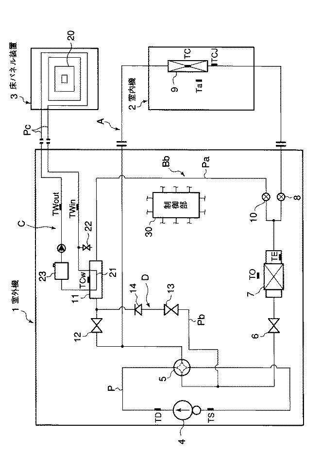
図1は第1の実施の形態に係る、床暖房付き空気調和機のサイクル構成図である。
この空気調和機は、室外に配置される室外機1と、被空調室のたとえば壁面に取付けられる室内機2および床面に設けられる床暖房パネル3とから構成される。
上記室外機1には、圧縮機4、四方切換え弁5、室外熱交換器7、電動膨張弁で構成される主絞り装置8、電動膨張弁で構成される補助絞り装置10、制御手段である制御部30、水熱交換器11、給水タンク23および循環ポンプ24が収容される。上記室内機2には室内熱交換器9が収容され、上記床暖房パネル3は床面に埋設される放熱管20から構成される。
Embodiments of the present invention will be described below with reference to the drawings.
FIG. 1 is a cycle configuration diagram of an air conditioner with floor heating according to a first embodiment.
This air conditioner includes an outdoor unit 1 disposed outside, an indoor unit 2 attached to, for example, a wall surface of the air-conditioned room, and a floor heating panel 3 provided on the floor surface.
The outdoor unit 1 includes a
上記圧縮機4と、四方切換え弁5と、室外熱交換器7と、主絞り装置8と、室内熱交換器9は冷媒管Pを介してヒートポンプ式の冷凍サイクルであるメイン回路(以下、冷凍サイクル回路と呼ぶ)Aを構成するように連通される。
上記圧縮機1の吐出部aと四方切換え弁5とを連通する冷媒管Pの中途部と、上記室外熱交換器7と主絞り装置8とを連通する冷媒管Pの中途部には、バイパス管Paの端部が接続される。このバイパス管Paの中途部には補助絞り装置10と、水熱交換器11および第1の開閉弁12が直列に設けられ、これらでバイパス回路Bが構成される。
The
In the middle of the refrigerant pipe P that communicates the discharge part a of the compressor 1 and the four-way switching valve 5 and in the middle of the refrigerant pipe P that communicates the outdoor heat exchanger 7 and the main throttle device 8, The end of the tube Pa is connected. In the middle of the bypass pipe Pa, the
一方、上記床暖房パネル3を構成する放熱管20は、床面面積に対して均等に張り巡らされ、かつ1つの流路からなる。そして、上記放熱管20の両端部は被空調室の床面から突出している。
上記水熱交換器11内には熱交換部21が収容され、この熱交換部21の一端は上記床面から突出する放熱管20の一端に温水管Pcを介して連通し、中途部に分岐して水抜き栓22が設けられる。熱交換部21の他端は床面から突出する放熱管20の他端部に温水管Pcを介して連通していて、この温水管Pcの中途部に給水タンク23と循環ポンプ24が直列に設けられ、これらでループ状の温水循環回路Cが構成される。
On the other hand, the
A
なお、それぞれの回路A〜Cには複数のセンサが取付けられていて、全て上記制御部30に対して検知信号を送る。これらの検知信号を受けた制御部30は、以下に述べるような各運転モードにおける制御条件を整える。
すなわち、上記冷凍サイクル回路Aにおいて、圧縮機4の吐出部a近傍に圧縮機4から吐出される冷媒ガスの温度を検知するセンサTDが取付けられ、圧縮機4の吸込み部b近傍に吸込みガス温度を検知するセンサTSが取付けられる。上記室外熱交換器7には、室外熱交換器7における冷媒温度を検知するセンサTEが取付けられる。
A plurality of sensors are attached to each of the circuits A to C, and all send detection signals to the
That is, in the refrigeration cycle circuit A, a sensor TD for detecting the temperature of the refrigerant gas discharged from the
上記室内熱交換器9には、室内熱交換器9における冷媒温度を検知するセンサTaと、冷房運転時における室内熱交換器9の入り口側冷媒温度を検知するセンサTCJおよび室内熱交換器9中間部の冷媒温度を検知するセンサTCが取付けられる。
上記バイパス回路Bにおいては、水熱交換器11における冷媒温度を検知するセンサTCwが取付けられる。上記温水循環回路Cにおいては、熱交換部21から導出され床暖房パネル3に送られる温水の温度を検知するTWoutと、床暖房パネル3から熱交換部21に戻る温水の温度を検知するTWoutが取付けられる。
上記制御部30は、上述したそれぞれのセンサTD,TS…から検知信号を受け、予め記憶されている基準値や、遠隔操作盤(リモコン)に指示される設定値などと比較演算して、圧縮機4、四方切換え弁5、主絞り装置8他の電動部品に制御信号を送り必要な制御をなす。
The
In the bypass circuit B, a sensor TCw for detecting the refrigerant temperature in the
The
つぎに、このようにして構成される床暖付き空気調和装置の作用について説明する。
(1) 室内機による暖房運転
室内機による暖房運転とは、室内機2の室内熱交換器9による暖房作用を言う。
この室内機による暖房運転が指示された場合は、制御部30は四方切換え弁5をOFFとし、第1の開閉弁12を開放する。そして、制御部30は室外熱交換器7に設けられるセンサTEと圧縮機4の吸込み部b近傍に設けられるセンサTSの検知信号を受け、これらセンサの検出値の差(TE−TS)を演算し、室内熱交換器9への冷媒循環量を調整して室外熱交換器7の出口側において冷媒がすべて蒸発し過熱状態となるように、主絞り装置8での冷媒絞り量を最適に制御する。(以下、スーパーヒート制御と呼び、SH制御と記す)
また、制御部30は上記補助絞り装置10に対してほとんど全閉に近い状態の開度(たとえば、44パルス)となるように制御する。そして、制御部30は温水循環回路Cにおける循環ポンプ24の駆動を停止するように制御する。
しかして、図1に実線矢印で示すように、圧縮機4で圧縮され吐出された高温高圧の冷媒ガスは、四方切換え弁5を介して室内機2内の室内熱交換器9に導かれ凝縮液化する。このとき凝縮熱を放出して、ここに導かれる室内空気を温度上昇させ室内の暖房作用をなす。室内熱交換器9で液化した冷媒は主絞り装置8によって減圧され、室外熱交換器7および四方切換え弁5を介して圧縮機1に吸込まれ、上述のサイクルを循環する。
Next, the operation of the air conditioner with warm floor constructed as described above will be described.
(1) Heating operation by indoor unit
The heating operation by the indoor unit refers to a heating operation by the
When the heating operation by the indoor unit is instructed, the
Further, the
1, the high-temperature and high-pressure refrigerant gas compressed and discharged by the
なお、この場合のSH制御として制御部30は、室外熱交換器7の冷媒入り口側で検知された冷媒温度TEと圧縮機4の吸込み部b近傍で検知された冷媒温度の検知信号を受け、これらの差(TE−TS)を演算した結果を、蒸発器である室外熱交換器7のSH量とする。そして、制御部30は上記SH量がある設定となるまで主絞り装置8の室内熱交換器9への冷媒絞り量を最適に制御する。したがって、室内熱交換器9における暖房能力の増大化を得られる。
上記バイパス回路Bにおいて補助絞り装置10の開度は微小量であり、上記循環ポンプ24は停止していて熱交換部21に熱交換水が導かれていないから、冷媒と熱交換水との熱交換作用は行われない。また、補助絞り装置10の開度は微小量開いているため、水熱交換器11に滞留した冷媒は補助絞り装置10を介して室外熱交換器7側に導かれ回収される。
As the SH control in this case, the
In the bypass circuit B, the opening degree of the
(2) 室内機による冷房運転
室内機による冷房運転とは、室内機の室内熱交換器9による冷房作用を言う。
この室内機による冷房運転が指示された場合は、制御部30は四方切換え弁5をONに切換え、第1の開閉弁12の開放を継続する。そして、制御部30は室内熱交換器9の中間部に設けられるセンサTCと、圧縮機4の吸込み部b近傍に設けられるセンサTSの検知信号を受け、これらセンサの検出値の差(TC−TS)を演算して、室内熱交換器9でSH制御をなすよう主絞り装置8に対して冷媒絞り量を最適に設定する。
(2) Cooling operation by indoor unit
The cooling operation by the indoor unit refers to a cooling operation by the
When the cooling operation by the indoor unit is instructed, the
また、制御部30は上記補助絞り装置10に対してほとんど全閉に近い状態の開度(たとえば、44パルス)となるように制御し、循環回路Dにおける循環ポンプ24の駆動を停止する制御をなす。
しかして、図1に破線矢印で示すように、圧縮機4で圧縮され吐出された高温高圧の冷媒ガスは、四方切換え弁5を介して室外熱交換器7に導かれ凝縮液化する。そして、液冷媒は主絞り装置8によって減圧され、さらに室内熱交換器9に導かれ蒸発する。このとき蒸発潜熱を室内空気から奪って温度低下させ室内の冷房作用をなす。蒸発した冷媒は四方切換え弁5を介して圧縮機4に吸込まれ、上述のサイクルを循環する。
Further, the
1, the high-temperature and high-pressure refrigerant gas compressed and discharged by the
上記制御部30は、室内熱交換器9の出口側でSH制御をなし、室内熱交換器9全体での蒸発作用をなすように主絞り装置8における絞り量を最適に制御する。したがって、室内熱交換器9における冷房能力の増大化を得られる。
上記バイパス回路Bにおける補助絞り装置10の開度は微小量であり、上記循環ポンプ24は停止していて熱交換部21に熱交換水が導かれていないから、冷媒と熱交換水との熱交換作用は行われない。また、補助絞り装置10の開度は微小量開いているため、水熱交換器11に滞留した冷媒は補助絞り装置10を介して室内熱交換器9側に導かれ回収される。
The
Since the opening degree of the
(3) 室内機によるドライ運転
室内機によるドライ運転とは、室内機2の室内熱交換器9一部のみを用いて行う除湿作用を言う。
この室内機によるドライ運転が指示された場合は、制御部30は四方切換え弁5を室内機による冷房運転と同様にONとし、第1の開閉弁12の開放を継続する。そして、制御部30は室内熱交換器9の冷媒導入側に設けられるセンサTCJと、室内熱交換器9の中間部に設けられるセンサTCからの冷媒温度検知信号を受け、これらセンサの検出値の差(TCJ−TC)を演算してSH制御を行い、室内熱交換器9の入り口側の一部のみにおいて蒸発が完了するように過絞りを行うように主絞り装置8に対して冷媒絞り量を設定する。
(3) Dry operation by indoor unit
The dry operation by the indoor unit refers to a dehumidifying action performed using only a part of the
When the dry operation by the indoor unit is instructed, the
また、制御部30は上記補助絞り装置10に対してほとんど全閉に近い状態の開度(たとえば、44パルス)となるように制御する。温水循環回路Cにおける循環ポンプ24の駆動を停止する制御をなすことは変りがない。
しかして、図1に破線矢印で示すように、圧縮機4で圧縮され吐出された高温高圧の冷媒ガスは、四方切換え弁5を介して室外熱交換器7に導かれ凝縮液化する。そして、液冷媒は主絞り装置8によって過絞り制御されて室内熱交換器9に導かれ、室内熱交換器9の一部においてのみ蒸発する。室内熱交換器9から導出される以前に、室内熱交換器9の途中で完全蒸発した冷媒は四方切換え弁5を介して圧縮機4に吸込まれ、上述のサイクルを循環する。
Further, the
1, the high-temperature and high-pressure refrigerant gas compressed and discharged by the
したがって、室内熱交換器9の入り口側部分で冷媒はほとんど完全蒸発する。この状態で室内熱交換器9の入り口側部分は、通常の全体的に蒸発器として機能する場合と比較してより低温となり、潜熱が増加する。すなわち、室内熱交換器9に導かれる室内空気の一部から蒸発潜熱を奪って温度低下させるが、室内熱交換器9の他の部分は冷媒蒸発作用が行われず温度低下が生じない。
このため、上記の蒸発作用が行われた部分で温度低下がなされ除湿された空気は、温度低下されないで通過する空気と混合され、全体としては温度低下の無い除湿された空気が室内に供給され、効率の良い除湿作用が行われる。
一方、上記バイパス回路Bにおける補助絞り装置10の開度は微小量であり、上記循環ポンプ24は停止していて熱交換部21に熱交換水が導かれていないから、冷媒と熱交換水との熱交換作用は行われない。また、補助絞り装置10の開度は微小量開いているため、水熱交換器11に滞留した冷媒は補助絞り装置10を介して室内熱交換器9側に導かれ回収される。
Therefore, the refrigerant almost completely evaporates at the entrance side portion of the
For this reason, the air that has been dehumidified and dehumidified in the portion where the evaporation action has been performed is mixed with the air that passes without being depressurized, and as a whole, dehumidified air that has no temperature decrease is supplied into the room. Efficient dehumidifying action is performed.
On the other hand, the opening degree of the
(4) 床暖房運転
床暖房運転とは、床暖房パネル3による床暖房作用を言う。
この床暖房運転が指示された場合は、制御部30は四方切換え弁5を室内機による暖房運転と同様にOFFに切換え、第1の開閉弁12の開放を継続する。制御部30は、補助絞り装置10に対してほぼ全開に近い状態(約400パルス)に設定し、循環ポンプ24の運転を開始させる。
(4) Floor heating operation
The floor heating operation refers to a floor heating operation by the floor heating panel 3.
When this floor heating operation is instructed, the
また、制御部30は室内機による暖房運転と同様に室外熱交換器7に設けられるセンサTEと圧縮機4の吸込み部b近傍に設けられるセンサTSの検知信号を受け、これらセンサの検出値の差(TE−TS)を演算し、主絞り装置8に対し室外熱交換器7でSH制御をなすよう冷媒絞り量を設定する。
圧縮機4で圧縮され吐出された高温高圧の冷媒ガスが第1の開閉弁12を介して水熱交換器11に導かれ、凝縮液化する。このとき凝縮熱を放出して熱交換部21に導かれる熱交換水を温度上昇させ温水化する。循環ポンプの作用により、熱交換部21で得られた温水は床暖房パネル3に導かれ放熱管20で放熱する。したがって床面が直接暖められ、床暖房作用をなす。
The
The high-temperature and high-pressure refrigerant gas compressed and discharged by the
循環ポンプ24の作用により、放熱管20で放熱して温度低下した温水が給水タンク23と循環ポンプ24を介して再び熱交換部21に導かれ、水熱交換器11で凝縮熱を吸収して温度上昇し、再び床暖房パネル3に導かれて放熱する。このようにして温水が温水循環回路Cを循環する。
制御部30は、室外熱交換器7の冷媒入り口側に設けられたセンサTEで検知された冷媒温度と、圧縮機4の吸込み部b近傍に設けられたセンサTSで検知された冷媒温度の検知信号を受け、これらの差(TE−TS)を演算した結果を冷媒の蒸発作用をなす室外熱交換器7のSH量として、主絞り装置8の絞り量を制御する。
すなわち、上記制御部30は室外熱交換器7の冷媒蒸発作用を検出し、主絞り装置8の絞り量を調整することで室内熱交換器9に溜まる冷媒を回収する。また、室内熱交換器9が過冷却状態になると、主絞り装置8の絞りを緩めて室内熱交換器9からの冷媒を回収するので、床暖房能力の増大化を得られる。
Due to the action of the
The
That is, the
(5) 室内機による暖房+床暖房運転
室内機による暖房+床暖房運転とは、上述した室内機による暖房作用と床暖房作用を同時に行うことを言う。
この室内機による暖房+床暖房運転が指示された場合は、制御部30は四方切換え弁5を室内機による暖房運転と同様にOFFに切換え、第1の開閉弁12の開放を継続する。そして、制御部30は室内機による暖房運転と同様に室外熱交換器7に設けられるセンサTEと圧縮機4の吸込み部b近傍に設けられるセンサTSの検知信号を受け、これらセンサの検出値の差(TE−TS)を演算して、室外熱交換器7においてSH制御をなすよう主絞り装置8の冷媒絞り量を最適に制御する。
(5) Indoor unit heating + floor heating operation
The heating by the indoor unit + floor heating operation means that the heating operation and the floor heating operation by the indoor unit described above are performed simultaneously.
When the heating by the indoor unit + floor heating operation is instructed, the
さらに制御部30は、補助絞り装置10に対してほぼ全閉に近い状態(約50パルス)に設定して、圧縮機4から室内機2と床暖房パネル3に導かれる冷媒ガスの量が、略9:1となるように制御する。そして、循環ポンプ24の運転が開始される。
圧縮機4で圧縮され吐出された高温高圧の冷媒ガスのほとんど大部分が、四方切換え弁5を介して室内機2内の室内熱交換器9に導かれて凝縮液化する。このとき凝縮熱を放出して、ここに導かれる室内空気を温度上昇させ室内の暖房作用をなす。室内熱交換器9で液化した冷媒は主絞り装置8によって流量制御され、室外熱交換器7および四方切換え弁5を介して圧縮機1に吸込まれ、上述のサイクルを循環する。
Further, the
Almost most of the high-temperature and high-pressure refrigerant gas compressed and discharged by the
また、圧縮機4から吐出される冷媒ガスの一部が第1の開閉弁12を介して水熱交換器11に導かれ、凝縮液化する。このとき凝縮熱を放出して、熱交換部21に導かれる熱交換水を温度上昇させ温水化する。循環ポンプの作用により、熱交換部21で得られた温水は床暖房パネル3に導かれて放熱管20で放熱する。したがって床面が直接暖められ、床暖房作用をなす。
循環ポンプ24の作用により、放熱管20で放熱して温度低下した温水は給水タンク23と循環ポンプ24を介して再び熱交換部21に導かれ、水熱交換器11で凝縮熱を吸収して温度上昇し、再び床暖房パネル3に導かれて放熱する。このようにして温水が温水循環回路Cを循環する。
Further, a part of the refrigerant gas discharged from the
Due to the action of the
制御部30は、室外熱交換器7の冷媒入り口側に設けられたセンサTEで検知された冷媒温度と、圧縮機4の吸込み部b近傍に設けられたセンサTSで検知された冷媒温度の検知信号を受け、これらの差(TE−TS)を演算した結果を蒸発器である室外熱交換器7のSH量として、主絞り装置8の絞り量を制御し室内熱交換器9への冷媒循環量を調整する。したがって、暖房能力と床暖房能力の増大化が得られる。
なお、この運転の開始時においては、室内熱交換器9と熱交換した室内空気(温風)を下側である床面側へ向けて吹出し、いわゆる足元に対する暖房を重点的に行う。そして、室内温度が設定温度にまで上昇した状態では、室内熱交換器9と熱交換したあとの室内空気を斜め上方向へ吹出すように調整する。したがって、居住人にとっては座り姿勢と立ち姿勢の如何を問わずに、ドラフト感を感じることのない快適暖房が得られる。
The
At the start of this operation, indoor air (warm air) exchanged with the
(6) 室内機による冷房+床暖房運転
室内機による冷房+床暖房運転とは、上述した室内機による冷房作用と床暖房作用を同時に行うことを言う。
この室内機による暖房+床暖房運転が指示された場合は、制御部30は四方切換え弁5を室内機による冷房運転と同様にONに切換え、第1の開閉弁12の開放を継続する。そして、制御部30は室内機による冷房運転と同様に室内熱交換器9の中間部に設けられるセンサTCと圧縮機4の吸込み部b近傍に設けられるセンサTSの検知信号を受け、これらセンサの検出値の差(TC−TS)を演算し、主絞り装置8に対し室内熱交換器9においてSH制御をなすよう冷媒絞り量を最適に制御する。
(6) Cooling and floor heating operation by indoor unit
The cooling and floor heating operation by the indoor unit refers to performing the cooling operation and the floor heating operation by the indoor unit described above at the same time.
When the heating by the indoor unit + floor heating operation is instructed, the
さらに制御部30は、補助絞り装置10に対してほぼ全閉に近い状態(約60パルス)に設定して、圧縮機4から室内機2と床暖房パネル3に導かれる冷媒ガスの量が、略9:1となるように制御する。そして、循環ポンプ24の運転が開始される。
圧縮機4で圧縮され吐出された高温高圧の冷媒ガスのほとんど大部分が、四方切換え弁5を介して室外熱交換器7に導かれて凝縮液化する。液化した冷媒は主絞り装置8によって流量制御され、室内熱交換器9で蒸発し室内空気から蒸発潜熱を奪って室内の冷房作用をなす。
Furthermore, the
Most of the high-temperature and high-pressure refrigerant gas compressed and discharged by the
また、圧縮機4から吐出される冷媒ガスの一部が第1の開閉弁12を介して水熱交換器11に導かれ、凝縮液化する。このとき凝縮熱を放出して、熱交換部21に導かれる熱交換水を温度上昇させる。循環ポンプの作用により、熱交換部21で得られた温水は床暖房パネル3に導かれて放熱管20で放熱する。したがって床面が直接暖められ、床暖房作用をなす。
上記制御部30は、室内熱交換器9の中間部に設けられたセンサTCで検知された冷媒温度と、圧縮機4の吸込み部b近傍に設けられたセンサTSで検知された冷媒温度の検知信号を受け、これらの差(TC−TS)を演算した結果を蒸発器である室内熱交換器9のSH量として、主絞り装置8の絞り量を制御し室内熱交換器9への冷媒循環量を調整する。
Further, a part of the refrigerant gas discharged from the
The
結局、室内熱交換器9の出口側におけるSHを制御し、室内熱交換器9全体で冷媒の蒸発作用が行われるように、室内熱交換器9への冷媒循環量を調整する。一方、冷媒の凝縮作用は室外熱交換器7と水熱交換器11とで行われるため、室内機2側への冷媒循環量の調整は容易に行えることとなる。
そして、床暖房作用は弱暖房であるため、室外機1に室外熱交換器7と対向して配置される図示しない室外送風機の送風量を調整し、室外熱交換器7における冷媒凝縮量を制御することで室内熱交換器9の蒸発負荷に応じた凝縮量の調整が容易に行える。したがって、冷房能力と床暖房能力の増大化が得られる。
Eventually, SH on the outlet side of the
And since the floor heating action is weak heating, the air flow rate of an outdoor fan (not shown) arranged on the outdoor unit 1 facing the outdoor heat exchanger 7 is adjusted, and the refrigerant condensation amount in the outdoor heat exchanger 7 is controlled. By doing so, the amount of condensation according to the evaporation load of the
(7)室内機によるドライ+床暖房運転
室内機によるドライ+床暖房運転とは、上述した除湿作用と床暖房作用とを同時に行うことを言う。
この室内機によるドライ運転が指示された場合は、制御部30は四方切換え弁5を室内機によるドライ運転と同様にONとし、第1の開閉弁12の開放を継続する。制御部30は室内熱交換器9の冷媒導入側に設けられるセンサTCJと、室内熱交換器9の中間部に設けられるセンサTCからの冷媒温度検知信号を受け、これらセンサの検出値の差(TCJ−TC)を演算してSH制御を行い、室内熱交換器9の入り口側の一部において蒸発作用が完了するよう主絞り装置8の冷媒絞り量を過絞り制御する。
(7) Dry + floor heating operation by indoor unit
Dry + floor heating operation by an indoor unit means that the above-described dehumidifying action and floor heating action are performed simultaneously.
When the dry operation by the indoor unit is instructed, the
また、制御部30は上記補助絞り装置10に対してほとんど全閉に近い状態の開度(たとえば、60パルス)となるように設定して、圧縮機4から室内機2と床暖房パネル3に導かれる冷媒ガスの量が、略9:1となるように制御する。そして、循環ポンプ24の運転が開始される。
しかして、圧縮機4で圧縮され吐出された高温高圧の冷媒ガスは、四方切換え弁5を介して室外熱交換器7に導かれ凝縮液化する。液冷媒は主絞り装置8によって流量制御され、さらに室内熱交換器9に導かれ、室内熱交換器9の一部においてのみ蒸発する。室内熱交換器9から導出される以前に、室内熱交換器9内で蒸発した冷媒は四方切換え弁5を介して圧縮機4に吸込まれ、上述のサイクルを循環する。
Further, the
Thus, the high-temperature and high-pressure refrigerant gas compressed and discharged by the
したがって、室内熱交換器9の入り口側部分で冷媒はほとんど完全蒸発してしまい、室内熱交換器9の入り口側部分は、通常の全体的に蒸発器として機能する場合と比較してより低温となり、潜熱が増加する。室内熱交換器9の他の部分は冷媒蒸発作用が行われず温度低下が生じない。
このため、上記の蒸発作用が行われた部分で温度低下がなされ除湿された空気は、温度低下されないで通過する空気と混合され、全体としては温度低下の無い除湿された空気が室内に供給され、ここに導かれる室内空気の温度を下げずに熱交換が行われる。上記した室内機によるドライ運転と同様に室内熱交換器9での除湿作用を行えるとともに、床暖房によって室内下部温度の低下を抑制して快適な室内空間が得られる。
Therefore, the refrigerant almost completely evaporates at the inlet side portion of the
For this reason, the air that has been dehumidified and dehumidified in the portion where the evaporation action has been performed is mixed with the air that passes without being depressurized, and as a whole, dehumidified air that has no temperature decrease is supplied into the room. Heat exchange is performed without lowering the temperature of the indoor air led here. Similar to the dry operation by the indoor unit described above, a dehumidifying action can be performed in the
冷媒の凝縮作用は、室外熱交換器7と床暖房パネル3とで行われることとなり、室内熱交換器9への冷媒循環量の調整が容易に行える。そして、床暖房は弱暖房であるため、室外熱交換器7と対向して配置される図示しない室外送風機の送風量を調整して室外熱交換器7における冷媒凝縮量を制御する。室内熱交換器9の蒸発負荷に応じた凝縮量の調整が容易に行える。
なお説明すると、この運転は冷媒の凝縮作用を室外熱交換器9と床暖房パネル3とで行うので、所望の容量の凝縮量がそれぞれで得られる。したがって、室内熱交換器9での蒸発能力が大きく取れるとともに、室内熱交換器9の一部で過絞りによる蒸発作用を行うため、除湿能力を大きく保持した運転が可能となる。
このようにして、基本的に7種類の運転切換えが可能であり、以下の[表1]に各運転モードと主たる制御対象部品に対する制御状態を一覧表にて示す。
In other words, in this operation, since the refrigerant condensing action is performed by the
In this way, basically seven types of operation switching are possible, and the following [Table 1] shows a list of control states for each operation mode and main control target components.
そして、これらの運転モードとは別に、必要に応じて除湿運転、空気清浄化運転、換気運転、酸素富化運転、マイナスイオン運転等のメリット運転が単独で可能である。
図2は、本発明の第2の実施の形態に係る床暖付き空気調和機のサイクル構成図である。
この空気調和機は、室外に配置される室外機1と、被空調室のたとえば壁面に取付けられる室内機2および被空調室の床面に設けられる床暖房パネル3とから構成される。室外機1に収容される圧縮機4と、四方切換え弁5と、室外熱交換器7および主絞り装置8が、上記室内機2に収容される室内熱交換器9とともに冷媒管Pを介してヒートポンプ式の冷凍サイクル回路Aを構成するように連通される。
In addition to these operation modes, merit operation such as dehumidification operation, air purification operation, ventilation operation, oxygen enrichment operation, and negative ion operation can be independently performed as necessary.
FIG. 2 is a cycle configuration diagram of the air conditioner with warm floor according to the second embodiment of the present invention.
The air conditioner includes an outdoor unit 1 disposed outside, an indoor unit 2 attached to, for example, a wall surface of the air-conditioned room, and a floor heating panel 3 provided on the floor of the air-conditioned room. The
上記室内機2と四方切換え弁5とを連通する冷媒管Pの中途部と、上記室外熱交換器7と主絞り装置8とを連通する冷媒管Pの中途部には、バイパス管Paの端部が接続される。このバイパス管Paの中途部には補助絞り装置10と、水熱交換器11および第1の開閉弁12が直列に設けられ、これらでバイパス回路Bbが構成される。
上記床暖房パネル3は床面に埋設された放熱管20からなり、上記水熱交換器11内には熱交換部21が収容されて、温水管Pcを介して連通する。温水管Pcの中途部に分岐して水抜き栓22と、給水タンク23および循環ポンプ24が設けられ、これらで温水循環回路Cが構成される。
An intermediate portion of the refrigerant pipe P that communicates the indoor unit 2 and the four-way switching valve 5 and an intermediate portion of the refrigerant pipe P that communicates the outdoor heat exchanger 7 and the main expansion device 8 are connected to the end of the bypass pipe Pa. Parts are connected. In the middle of the bypass pipe Pa, the
The floor heating panel 3 is composed of a
ここでは、上記四方切換え弁5と室外熱交換器7とを連通する冷媒管Pの中途部に主開閉弁6が設けられる。この主開閉弁6と四方切換え弁5とを連通する冷媒管Pの中途部と、上記バイパス回路Bbにおける第1の開閉弁12と水熱交換器12とを連通する温水管Pcの中途部にバイパス管Pbが設けられる。このバイパス管Pbには第2の開閉弁13と逆止弁14が設けられ、これらで補助バイパス回路Dが構成される。
それぞれの回路A〜Cにおけるセンサとして、室外熱交換器7に送風される外気の温度を検知するセンサTOが取付けられることの他は、全て先に第1の実施の形態で説明したものと同一であるので、同番号を付して新たな説明は省略する。
Here, a main on-off
As the sensors in the circuits A to C, all are the same as those described in the first embodiment, except that the sensor TO for detecting the temperature of the outside air blown to the outdoor heat exchanger 7 is attached. Therefore, the same number is attached and new explanation is omitted.
また、上記室外機1には制御手段である制御部30が設けられ、この制御部30は上述したそれぞれのセンサTD,TS…から検知信号を受けて予め記憶されている基準値や、遠隔操作盤(リモコン)に指示される設定値などと比較演算して、圧縮機4と、四方切換え弁5と、主絞り装置8および、その他の電動部品に制御信号を送り必要な制御をなすことも変りがない。
しかして、主開閉弁6と第1の開閉弁12を開放し、第2の開閉弁13を閉成したうえで、先に第1の実施の形態で説明したのと全く同様に、(1)室内機による暖房運転、(2)室内機による冷房運転、(3)室内機によるドライ運転、(4)床暖房運転、(5)室内機による暖房+床暖房運転が行えるとともに、制御部30は必要なSH制御をなす。ここでは、第1の実施の形態での説明を適用して新たな説明は省略する。
Further, the outdoor unit 1 is provided with a
Thus, after opening the main on-off
また、(6)室内機による冷房+床暖房運転および(7)室内機によるドライ+床暖房運転を行う場合は、制御部30は主開閉弁6の開閉を制御するとともに、第1の開閉弁12を閉成し、第2の開閉弁13を開放する。なお、上記制御部30のSH制御に関する設定は全く変りがない。
したがって、圧縮機4から吐出される冷媒ガスが四方切換え弁5を通過したあと、一部の冷媒ガスはそのまま冷凍サイクル回路Aを循環し、室内熱交換器9で蒸発して冷房作用もしくは除湿作用をなす。
In addition, when performing (6) cooling + floor heating operation by the indoor unit and (7) dry + floor heating operation by the indoor unit, the
Therefore, after the refrigerant gas discharged from the
上記四方切換え弁5を通過したあとの残りの冷媒は補助バイパス回路Dに分流され、水熱交換器11において凝縮して温水循環回路Cの熱交換部21に導かれる熱交換水に凝縮熱を放出する。温度上昇した温水は床暖房パネル3を構成する放熱管20で放熱して床暖房をなす。
いずれの運転も、冷媒の凝縮作用は室外熱交換器7と床暖房パネル3とで行われ、室内熱交換器9への冷媒循環量の調整が容易となる。床暖房運転は弱暖房であるため、室外送風機の送風量を調整して室外熱交換器7における冷媒凝縮量を制御することで、室内熱交換器9の蒸発負荷に応じた凝縮量の調整が容易に行える。
なお説明すると、この運転は冷媒の凝縮作用を室外熱交換器9と床暖房パネル3とで行うため、所望の容量の凝縮量がそれぞれで得られ、室内熱交換器9での蒸発能力が大きく取れるとともに、室内熱交換器9の一部で過絞りによる蒸発作用を行うため、除湿能力を大きく保持する運転が可能となる。
The remaining refrigerant after passing through the four-way switching valve 5 is diverted to the auxiliary bypass circuit D, condensed in the
In any operation, the refrigerant condensing action is performed by the outdoor heat exchanger 7 and the floor heating panel 3, and the refrigerant circulation amount to the
In other words, in this operation, since the refrigerant condensing action is performed by the
1…室外機、2…室内機、3…床暖房パネル、4…圧縮機、5…四方切換え弁、7…室外熱交換器、8…主絞り装置、9…室内熱交換器、P…冷媒管、10…補助絞り装置、11…水熱交換器、A…冷凍サイクル回路(メイン回路)、B、Bb…バイパス回路、20…放熱管、21…熱交換部、23…給水タンク、24…循環ポンプ、C…温水循環回路、D…補助バイパス回路。 DESCRIPTION OF SYMBOLS 1 ... Outdoor unit, 2 ... Indoor unit, 3 ... Floor heating panel, 4 ... Compressor, 5 ... Four-way switching valve, 7 ... Outdoor heat exchanger, 8 ... Main throttle device, 9 ... Indoor heat exchanger, P ... Refrigerant Pipes, 10 ... auxiliary throttle device, 11 ... water heat exchanger, A ... refrigeration cycle circuit (main circuit), B, Bb ... bypass circuit, 20 ... radiation pipe, 21 ... heat exchange section, 23 ... water supply tank, 24 ... Circulation pump, C ... warm water circulation circuit, D ... auxiliary bypass circuit.
Claims (2)
上記圧縮機、四方切換え弁、室外熱交換器、主絞り装置および室内熱交換器とを冷媒管を介して連通するヒートポンプ式の冷凍サイクルを構成するメイン回路と、
上記圧縮機の吐出部と四方切換え弁とを連通する冷媒管の中途部と、上記室外熱交換器と主絞り装置とを連通する冷媒管の中途部との間に接続され、上記水熱交換器および補助絞り装置を備えたバイパス回路と、
上記床暖房パネルを構成する放熱管と、上記水熱交換器内に収容される熱交換部との間でループ状に接続され、給水タンクおよび循環ポンプを備えた温水循環回路と、
上記室内機による暖房+床暖房パネルによる暖房運転時に、室外熱交換器の冷媒入り口側の冷媒温度TEと、圧縮機の吸込み側冷媒温度TSとの差から上記室外熱交換器のスーパーヒート状態を算出して室内熱交換器と水熱交換器への冷媒循環量を上記主絞り装置と補助絞り装置により制御し、
上記室内機による冷房+床暖房パネルによる暖房運転時に、室内熱交換器の中間部の冷媒温度TCと、圧縮機の吸込み側冷媒温度TSとの差から上記室内熱交換器のスーパーヒート状態を算出して上記主絞り装置を制御し、
上記室内機によるドライ+床暖房パネルによる暖房運転時に、上記室内熱交換器の冷媒入り口側温度TCJと、室内熱交換器の中間部の冷媒温度TCとの差から室内熱交換器の入り口側部分で冷媒蒸発作用が完了するようにスーパーヒート状態を算出して上記主絞り装置を過絞り制御する制御手段と
を具備することを特徴とする床暖房付き空気調和機。 A compressor, a four-way switching valve, an outdoor heat exchanger, a main throttle device, a water heat exchanger, an outdoor unit containing an auxiliary throttle device that controls the amount of refrigerant circulation to the water heat exchanger, and an indoor heat exchanger It consists of an indoor unit and a floor heating panel to which hot water from a water heat exchanger is supplied,
A main circuit constituting a heat pump refrigeration cycle in which the compressor, the four-way switching valve, the outdoor heat exchanger, the main throttle device, and the indoor heat exchanger are communicated with each other via a refrigerant pipe;
Connected between the middle part of the refrigerant pipe communicating with the discharge part of the compressor and the four-way switching valve, and the middle part of the refrigerant pipe communicating with the outdoor heat exchanger and the main throttle device, the water heat exchange A bypass circuit with a vacuum device and an auxiliary throttle device;
A hot water circulation circuit that is connected in a loop between a heat radiating pipe that constitutes the floor heating panel and a heat exchange unit that is accommodated in the water heat exchanger, and includes a water supply tank and a circulation pump;
During the heating operation by the indoor unit + floor heating panel, the superheat state of the outdoor heat exchanger is determined from the difference between the refrigerant temperature TE on the refrigerant inlet side of the outdoor heat exchanger and the refrigerant temperature TS on the suction side of the compressor. Calculate and control the refrigerant circulation amount to the indoor heat exchanger and the water heat exchanger by the main throttle device and the auxiliary throttle device,
The superheat state of the indoor heat exchanger is calculated from the difference between the refrigerant temperature TC in the middle part of the indoor heat exchanger and the suction side refrigerant temperature TS of the compressor during the cooling operation by the indoor unit and the heating operation by the floor heating panel. To control the main diaphragm device,
During the heating operation by the dry + floor heating panel by the indoor unit, the inlet side portion of the indoor heat exchanger is determined from the difference between the refrigerant inlet side temperature TCJ of the indoor heat exchanger and the refrigerant temperature TC of the intermediate portion of the indoor heat exchanger. And an air conditioner with floor heating, comprising a control means for calculating the superheat state so that the refrigerant evaporating action is completed and over-controlling the main throttle device.
上記圧縮機、四方切換え弁、室外熱交換器、主絞り装置および室内熱交換器とを冷媒管を介して連通するヒートポンプ式の冷凍サイクルを構成するメイン回路と、
上記室内熱交換器と四方切換え弁とを連通する冷媒管の中途部と、上記室外熱交換器と主絞り装置とを連通する冷媒管の中途部との間に接続され、上記水熱交換器および補助絞り装置を備えたバイパス回路と、
上記四方切換え弁と室外熱交換器とを連通する冷媒管の中途部と、上記バイパス回路の上記メイン回路接続部と水熱交換器とを連通するバイパス管の中途部との間に接続され、開閉弁を備えた補助バイパス回路と、
上記床暖房パネルを構成する放熱管と、上記水熱交換器内に収容される熱交換部との間でループ状に接続され、給水タンクおよび循環ポンプを備えた温水循環回路と、
上記室内機による暖房+床暖房パネルによる暖房運転時に、室外熱交換器の冷媒入り口側の冷媒温度TEと、圧縮機の吸込み側冷媒温度TSとの差から上記室外熱交換器のスーパーヒート状態を算出して室内熱交換器と水熱交換器への冷媒循環量を上記主絞り装置と補助絞り装置により制御し、
上記室内機による冷房+床暖房パネルによる暖房運転時に、室内熱交換器の中間部の冷媒温度TCと、圧縮機の吸込み側冷媒温度TSとの差から上記室内熱交換器のスーパーヒート状態を算出して上記主絞り装置を制御し、
上記室内機によるドライ+床暖房パネルによる暖房運転時に、上記室内熱交換器の冷媒入り口側温度TCJと、室内熱交換器の中間部の冷媒温度TCとの差から室内熱交換器の入り口側部分で冷媒蒸発作用が完了するようにスーパーヒート状態を算出して上記主絞り装置を過絞り制御する制御手段と
を具備することを特徴とする床暖房付き空気調和機。 A compressor, a four-way switching valve, an outdoor heat exchanger, a main throttle device, a water heat exchanger, an outdoor unit containing an auxiliary throttle device that controls the amount of refrigerant circulation to the water heat exchanger, and an indoor heat exchanger It consists of an indoor unit and a floor heating panel to which hot water from a water heat exchanger is supplied,
A main circuit constituting a heat pump refrigeration cycle in which the compressor, the four-way switching valve, the outdoor heat exchanger, the main throttle device, and the indoor heat exchanger are communicated with each other via a refrigerant pipe;
The water heat exchanger is connected between a midway portion of the refrigerant pipe that communicates the indoor heat exchanger and the four-way switching valve and a midway portion of the refrigerant pipe that communicates the outdoor heat exchanger and the main throttle device. And a bypass circuit with an auxiliary throttle device;
It is connected between the middle part of the refrigerant pipe that communicates the four-way switching valve and the outdoor heat exchanger, and the middle part of the bypass pipe that communicates the main circuit connection part of the bypass circuit and the water heat exchanger, An auxiliary bypass circuit with an on-off valve;
A hot water circulation circuit that is connected in a loop between a heat radiating pipe that constitutes the floor heating panel and a heat exchange unit that is accommodated in the water heat exchanger, and includes a water supply tank and a circulation pump;
During the heating operation by the indoor unit + floor heating panel, the superheat state of the outdoor heat exchanger is determined from the difference between the refrigerant temperature TE on the refrigerant inlet side of the outdoor heat exchanger and the refrigerant temperature TS on the suction side of the compressor. Calculate and control the refrigerant circulation amount to the indoor heat exchanger and the water heat exchanger by the main throttle device and the auxiliary throttle device,
The superheat state of the indoor heat exchanger is calculated from the difference between the refrigerant temperature TC in the middle part of the indoor heat exchanger and the suction side refrigerant temperature TS of the compressor during the cooling operation by the indoor unit and the heating operation by the floor heating panel. To control the main diaphragm device,
During the heating operation by the dry + floor heating panel by the indoor unit, the inlet side portion of the indoor heat exchanger is determined from the difference between the refrigerant inlet side temperature TCJ of the indoor heat exchanger and the refrigerant temperature TC of the intermediate portion of the indoor heat exchanger. And an air conditioner with floor heating, comprising a control means for calculating the superheat state so that the refrigerant evaporating action is completed and over-controlling the main throttle device.
Priority Applications (1)
| Application Number | Priority Date | Filing Date | Title |
|---|---|---|---|
| JP2004014241A JP4452083B2 (en) | 2004-01-22 | 2004-01-22 | Air conditioner with floor heating |
Applications Claiming Priority (1)
| Application Number | Priority Date | Filing Date | Title |
|---|---|---|---|
| JP2004014241A JP4452083B2 (en) | 2004-01-22 | 2004-01-22 | Air conditioner with floor heating |
Publications (2)
| Publication Number | Publication Date |
|---|---|
| JP2005207665A true JP2005207665A (en) | 2005-08-04 |
| JP4452083B2 JP4452083B2 (en) | 2010-04-21 |
Family
ID=34900090
Family Applications (1)
| Application Number | Title | Priority Date | Filing Date |
|---|---|---|---|
| JP2004014241A Expired - Fee Related JP4452083B2 (en) | 2004-01-22 | 2004-01-22 | Air conditioner with floor heating |
Country Status (1)
| Country | Link |
|---|---|
| JP (1) | JP4452083B2 (en) |
Cited By (4)
| Publication number | Priority date | Publication date | Assignee | Title |
|---|---|---|---|---|
| CN108800354A (en) * | 2018-06-19 | 2018-11-13 | 广东美的暖通设备有限公司 | Indoor dehumidification method and apparatus |
| CN110906482A (en) * | 2019-12-10 | 2020-03-24 | 海普电器有限公司 | Modular floor heating and air conditioning integrated machine |
| CN113063190A (en) * | 2021-04-02 | 2021-07-02 | 北京晶海科技有限公司 | Integrated circulation pipeline system for air conditioner and control method and control device thereof |
| CN113834201A (en) * | 2021-09-06 | 2021-12-24 | 美的集团武汉暖通设备有限公司 | Air conditioner control method, air conditioner and storage medium |
-
2004
- 2004-01-22 JP JP2004014241A patent/JP4452083B2/en not_active Expired - Fee Related
Cited By (6)
| Publication number | Priority date | Publication date | Assignee | Title |
|---|---|---|---|---|
| CN108800354A (en) * | 2018-06-19 | 2018-11-13 | 广东美的暖通设备有限公司 | Indoor dehumidification method and apparatus |
| CN110906482A (en) * | 2019-12-10 | 2020-03-24 | 海普电器有限公司 | Modular floor heating and air conditioning integrated machine |
| CN113063190A (en) * | 2021-04-02 | 2021-07-02 | 北京晶海科技有限公司 | Integrated circulation pipeline system for air conditioner and control method and control device thereof |
| CN113063190B (en) * | 2021-04-02 | 2023-01-13 | 北京晶海科技有限公司 | Integrated circulation pipeline system for air conditioner and control method and control device thereof |
| CN113834201A (en) * | 2021-09-06 | 2021-12-24 | 美的集团武汉暖通设备有限公司 | Air conditioner control method, air conditioner and storage medium |
| CN113834201B (en) * | 2021-09-06 | 2022-12-02 | 美的集团武汉暖通设备有限公司 | Air conditioner control method, air conditioner and storage medium |
Also Published As
| Publication number | Publication date |
|---|---|
| JP4452083B2 (en) | 2010-04-21 |
Similar Documents
| Publication | Publication Date | Title |
|---|---|---|
| CN109196287B (en) | Air conditioning system | |
| US5678417A (en) | Air conditioning apparatus having dehumidifying operation function | |
| US5316074A (en) | Automotive hair conditioner | |
| US8082749B2 (en) | Air conditioner | |
| JP4840207B2 (en) | Ventilation air conditioner | |
| JP2009222248A (en) | Air conditioning system and accumulator thereof | |
| JP2009058175A (en) | Ventilation air-conditioning device | |
| US20100243749A1 (en) | Humidity control apparatus | |
| JP2005257165A (en) | Air conditioner with floor heating | |
| JP2008190789A (en) | Air conditioner | |
| JPH0814389B2 (en) | Clean room with direct expansion heat exchanger | |
| JP4452083B2 (en) | Air conditioner with floor heating | |
| US8250878B2 (en) | Air conditioning and energy recovery system and method of operation | |
| JP3936345B2 (en) | Air conditioner | |
| KR101562744B1 (en) | Air handling system interworking with ventilation unit | |
| WO2019155614A1 (en) | Air-conditioning device, air-conditioning system, and heat exchange unit | |
| JP4074422B2 (en) | Air conditioner and its control method | |
| JP2009236415A (en) | Air-conditioning system | |
| JP7374633B2 (en) | Air conditioners and air conditioning systems | |
| JP2018112356A (en) | Air Conditioning System | |
| KR20170138703A (en) | Air conditioner system and its control method | |
| JP5066022B2 (en) | Air conditioning system | |
| KR20220098604A (en) | Constant temperature and humidity air conditioner using heat pump and the control method thereof | |
| JP2004044946A (en) | Air conditioner | |
| JP2003322363A (en) | Air conditioner |
Legal Events
| Date | Code | Title | Description |
|---|---|---|---|
| A621 | Written request for application examination |
Free format text: JAPANESE INTERMEDIATE CODE: A621 Effective date: 20060728 |
|
| A711 | Notification of change in applicant |
Free format text: JAPANESE INTERMEDIATE CODE: A712 Effective date: 20080528 |
|
| A977 | Report on retrieval |
Free format text: JAPANESE INTERMEDIATE CODE: A971007 Effective date: 20080730 |
|
| A131 | Notification of reasons for refusal |
Free format text: JAPANESE INTERMEDIATE CODE: A131 Effective date: 20090825 |
|
| A521 | Written amendment |
Free format text: JAPANESE INTERMEDIATE CODE: A523 Effective date: 20091026 |
|
| TRDD | Decision of grant or rejection written | ||
| A01 | Written decision to grant a patent or to grant a registration (utility model) |
Free format text: JAPANESE INTERMEDIATE CODE: A01 Effective date: 20100126 |
|
| A01 | Written decision to grant a patent or to grant a registration (utility model) |
Free format text: JAPANESE INTERMEDIATE CODE: A01 |
|
| A61 | First payment of annual fees (during grant procedure) |
Free format text: JAPANESE INTERMEDIATE CODE: A61 Effective date: 20100129 |
|
| R150 | Certificate of patent or registration of utility model |
Free format text: JAPANESE INTERMEDIATE CODE: R150 |
|
| FPAY | Renewal fee payment (event date is renewal date of database) |
Free format text: PAYMENT UNTIL: 20130205 Year of fee payment: 3 |
|
| LAPS | Cancellation because of no payment of annual fees |