JP2005207385A - Control method in hybrid system - Google Patents
Control method in hybrid system Download PDFInfo
- Publication number
- JP2005207385A JP2005207385A JP2004017502A JP2004017502A JP2005207385A JP 2005207385 A JP2005207385 A JP 2005207385A JP 2004017502 A JP2004017502 A JP 2004017502A JP 2004017502 A JP2004017502 A JP 2004017502A JP 2005207385 A JP2005207385 A JP 2005207385A
- Authority
- JP
- Japan
- Prior art keywords
- motor
- engine
- battery
- power
- generator
- Prior art date
- Legal status (The legal status is an assumption and is not a legal conclusion. Google has not performed a legal analysis and makes no representation as to the accuracy of the status listed.)
- Pending
Links
Images


Classifications
-
- Y—GENERAL TAGGING OF NEW TECHNOLOGICAL DEVELOPMENTS; GENERAL TAGGING OF CROSS-SECTIONAL TECHNOLOGIES SPANNING OVER SEVERAL SECTIONS OF THE IPC; TECHNICAL SUBJECTS COVERED BY FORMER USPC CROSS-REFERENCE ART COLLECTIONS [XRACs] AND DIGESTS
- Y02—TECHNOLOGIES OR APPLICATIONS FOR MITIGATION OR ADAPTATION AGAINST CLIMATE CHANGE
- Y02T—CLIMATE CHANGE MITIGATION TECHNOLOGIES RELATED TO TRANSPORTATION
- Y02T10/00—Road transport of goods or passengers
- Y02T10/60—Other road transportation technologies with climate change mitigation effect
- Y02T10/62—Hybrid vehicles
Landscapes
- Electric Propulsion And Braking For Vehicles (AREA)
- Hybrid Electric Vehicles (AREA)
- Control Of Vehicle Engines Or Engines For Specific Uses (AREA)
- Electrical Control Of Air Or Fuel Supplied To Internal-Combustion Engine (AREA)
- Combined Controls Of Internal Combustion Engines (AREA)
Abstract
Description
本発明は、ハイブリッドシステムに関し、特に、エンジンを駆動源とした発電機により発電された電力を、コンバータを介してバッテリに充電するハイブリッドシステムに関する。なお、本発明における「ハイブリッド」とは、エンジンから少なくとも機械的駆動力と電力を取り出すという意味である。 The present invention relates to a hybrid system, and more particularly to a hybrid system that charges a battery with electric power generated by a generator using an engine as a drive source via a converter. In the present invention, “hybrid” means that at least mechanical driving force and electric power are extracted from the engine.
従来、電気自動車や作業機などに適用されるハイブリッドシステムとして、電動機(モータ)と発電機とを別々に備えた構成のものと、電動機及び発電機の機能を兼ね備えたモータジェネレータを備えた構成のものとが知られている。
これらのハイブリッドシステムにおいては、発電機による発電電力の蓄電装置(バッテリ)への蓄電と、このバッテリの給電電力を用いたモータやモータとして作動するモータジェネレータの駆動によるトルクアシストとが行われている。
そして、このような発電機や電動機の作動について、例えばモータジェネレータを備えたハイブリッドシステムの場合に、予め設定される目標トルクに対応する燃料噴射量を燃料噴射量の目標値として用い、この目標値と燃料噴射量の実測値との比較結果に基づいて、モータジェネレータを電動機として作動させてトルクアシストを行うか、発電機として作動させてバッテリの蓄電を行うかを制御することで、エンジンを最適な運転状態に近付くようにする技術が公知となっている(例えば、特許文献1参照)。
Conventionally, as a hybrid system applied to an electric vehicle or a work machine, a configuration in which a motor (motor) and a generator are separately provided, and a configuration in which a motor generator having a function of the motor and the generator is provided are provided. Things are known.
In these hybrid systems, electric power generated by a generator is stored in a power storage device (battery), and torque assist is performed by driving a motor or a motor generator that operates as a motor using electric power supplied from the battery. .
For the operation of such a generator or electric motor, for example, in the case of a hybrid system equipped with a motor generator, a fuel injection amount corresponding to a preset target torque is used as a target value for the fuel injection amount. The engine is optimized by controlling whether the motor generator is operated as an electric motor to perform torque assist or the generator is operated as a battery to store the battery based on the comparison result between the fuel injection amount and the actual fuel injection amount. A technique for approaching a driving state is known (see, for example, Patent Document 1).
本発明が解決しようとする問題は、前述のような、バッテリからの給電電力を利用して駆動するモータやモータとして作動するモータジェネレータによってトルクアシストが行われるハイブリッドシステムにおいて、バッテリの充電量が減少することによってモータへの電力供給が十分になされず、モータによる安定したトルクアシストが行われない場合がある点である。また、モータによるトルクアシストが連続して行われることにより、バッテリの過放電状態が発生する場合がある点である。 The problem to be solved by the present invention is that the charge amount of the battery is reduced in the hybrid system in which torque assist is performed by the motor driven by the power supplied from the battery or the motor generator operating as the motor as described above. As a result, the power supply to the motor is not sufficient, and stable torque assist by the motor may not be performed. In addition, the battery may be overdischarged due to continuous torque assist by the motor.
しかし、前記従来のハイブリッドシステムなどにおいては、バッテリからの給電電力を利用して駆動するモータによるトルクアシストは、エンジンの負荷トルクの変化にともなう燃料噴射量の変化に基づいて行われるように制御されるものであり、例えば、仮にエンジンの負荷トルクが高い状態が続いたりすると、モータのトルクアシスト状態が連続することとなり、当然その分のバッテリの電力消費量も増加する。つまり、作業状態などによっては、発電機の発電電力によるバッテリへの充電量よりも、バッテリからの給電量の方が多くなることがある。このような場合、バッテリの充電量が少なくなり、トルクアシストを行うモータへの電力供給が十分になされず、作業中などに出力不足が生じたり、急激にエンジンの回転数が低下したりするおそれがある。このような状況が発生することとなると、モータによるトルクアシストによって機関出力を一定に保ち、エンジンの負荷平準化を図ることで、エンジンの小型化や燃費の向上を図ろうとするハイブリッドシステムとしての目的が損なわれてしまう。
また、上述のようにバッテリの充電量が不足した状態でモータが作動し続けると、バッテリからの給電も継続されることとなり、バッテリの過放電状態が発生する場合がある。このバッテリの過放電は、バッテリ性能の低下や劣化につながりバッテリ寿命を縮める原因となる。
However, in the conventional hybrid system and the like, torque assist by a motor driven using power supplied from a battery is controlled based on a change in fuel injection amount accompanying a change in engine load torque. For example, if the engine load torque continues to be high, for example, the motor torque assist state will continue, and the battery power consumption will naturally increase accordingly. That is, depending on the working state, the amount of power supplied from the battery may be larger than the amount of charge to the battery by the power generated by the generator. In such a case, the amount of charge of the battery is reduced, the power supply to the motor that performs torque assist is not sufficient, and there is a risk that the output will be insufficient during work or the engine speed may be drastically reduced. There is. When such a situation occurs, the purpose of the hybrid system is to reduce the engine size and improve fuel efficiency by maintaining the engine output constant by torque assist by the motor and leveling the engine load. Will be damaged.
In addition, if the motor continues to operate in a state where the amount of charge of the battery is insufficient as described above, power supply from the battery is continued, and an overdischarge state of the battery may occur. This overdischarge of the battery leads to a decrease or deterioration of the battery performance, and shortens the battery life.
そこで、本発明は、このような事情に鑑みてなされたものであり、その目的とするところは、バッテリからの給電電力を利用して駆動するモータによってトルクアシストが行われるハイブリッドシステムにおいて、バッテリの充電量が一定以上減少すると、モータによるトルクアシストを行わず、エンジン自体の出力を増加させるように制御することで、エンジンの負荷平準化を図るとともに、バッテリの過放電を防止してバッテリ性能の低下を抑制し長寿命化を図ることである。 Therefore, the present invention has been made in view of such circumstances, and an object of the present invention is to use a battery in a hybrid system in which torque assist is performed by a motor driven by using power supplied from the battery. When the amount of charge decreases more than a certain level, the motor is not torque-assisted and the engine output is controlled to increase, thereby achieving engine load leveling and preventing battery overdischarge. This is to suppress the decrease and to extend the life.
本発明の解決しようとする課題は以上の如くであり、次にこの課題を解決するための手段を説明する。 The problems to be solved by the present invention are as described above. Next, means for solving the problems will be described.
即ち、請求項1においては、エンジンと、モータと、これらを制御する制御手段と、発電機と、蓄電装置とを備え、前記エンジンの回転数をアクチュエータを介して調整する操作レバーによるエンジンの指示回転数が一定状態で、前記発電機によって発電された電力による前記蓄電装置の充電と、該蓄電装置から給電される電力によって駆動する前記モータによるトルクアシストとを制御することによって機関出力を一定に保持しようとするハイブリッドシステムであって、前記制御手段は、前記蓄電装置の充電状態が、予め設定された規定値を下回った場合、前記モータによるトルクアシストを行わず、前記アクチュエータを制御することによってエンジンの回転数を調節して機関出力を一定に保持するように制御するものである。 That is, according to the first aspect of the present invention, the engine is instructed by an operating lever that includes an engine, a motor, a control unit that controls these, a generator, and a power storage device, and that adjusts the rotational speed of the engine via an actuator. The engine output is kept constant by controlling charging of the power storage device by the power generated by the generator and torque assist by the motor driven by the power supplied from the power storage device with a constant rotational speed. In the hybrid system to be held, the control means controls the actuator without performing torque assist by the motor when the state of charge of the power storage device falls below a preset specified value. The engine speed is adjusted to keep the engine output constant.
請求項2においては、エンジンと、モータと、これらを制御する制御手段と、発電機と、蓄電装置とを備え、前記エンジンの回転数をアクチュエータを介して調整する操作レバーによるエンジンの指示回転数が一定状態で、前記発電機によって発電された電力による前記蓄電装置の充電と、該蓄電装置から給電される電力によって駆動する前記モータによるトルクアシストとを制御することによって機関出力を一定に保持しようとするハイブリッドシステムであって、前記制御手段は、前記モータのトルクアシストにともなう前記蓄電装置からの給電が終了した時から、予め設定された時間が経過するまでは、前記モータによるトルクアシストを行わず、前記アクチュエータを制御することによってエンジンの回転数を調節して機関出力を一定に保持するように制御するものである。 According to a second aspect of the present invention, there is provided an engine, a motor, a control means for controlling these, a generator, and a power storage device, and an engine designated rotational speed by an operating lever that adjusts the rotational speed of the engine via an actuator. The engine output is kept constant by controlling charging of the power storage device by the power generated by the power generator and torque assist by the motor driven by the power supplied from the power storage device in a constant state The control means performs torque assist by the motor from when power supply from the power storage device accompanying torque assist of the motor is completed until a preset time elapses. First, the engine output is adjusted by controlling the actuator to control the engine output. And controls to hold in.
本発明の効果として、以下に示すような効果を奏する。 As effects of the present invention, the following effects can be obtained.
請求項1においては、エンジンが長時間高負荷状態となってモータによるトルクアシストが連続して行われた場合などのように、蓄電装置の充電量が不足した状態でも、作業負荷に対するエンジンの特性(作業速度など)が変化することなく、作業中に蓄電装置の充電量不足にともなうモータのトルクアシストのトルク不足による違和感(機関回転数の急激な低下など)を解消することができる。また、蓄電装置の過放電を防止することができるので、蓄電装置の過放電によるバッテリ性能の低下を防止して長寿命化を図ることができる。 According to the first aspect of the present invention, even when the engine is in a high load state for a long time and torque assist by the motor is continuously performed, the engine characteristics with respect to the work load can be obtained even when the charge amount of the power storage device is insufficient. It is possible to eliminate a sense of incongruity (such as a rapid decrease in the engine speed) due to a lack of torque in the torque assist of the motor that accompanies a shortage of the charge amount of the power storage device during the work without changing (working speed or the like). In addition, since the overdischarge of the power storage device can be prevented, the battery performance can be prevented from being deteriorated due to the overdischarge of the power storage device, thereby extending the life.
請求項2においては、蓄電装置による給電が終了した時から一定時間は少なくとも蓄電装置の放電が行われることはないので、蓄電装置の過放電を予め防止することが可能となる。また、このような制御を行う場合をモードとして設定して切換え可能とすることで、作業状態に即して蓄電装置の過放電を防止できるとともに、エンジンの負荷平準化を図ることが可能となる。 According to the second aspect of the present invention, since the power storage device is not discharged at least for a certain period of time after the power supply by the power storage device is completed, it is possible to prevent the power storage device from being overdischarged in advance. In addition, by setting such a case where control is performed as a mode and enabling switching, overdischarge of the power storage device can be prevented in accordance with the working state, and engine load leveling can be achieved. .
次に、発明の実施の形態を説明する。
図1はハイブリッドシステムIの構成を示す図、図2はハイブリッドシステムIの動作モードの一覧を示す図、図3はハイブリッドシステムIのスタータ機能を示す説明図、図4はハイブリッドシステムIのアシスト機能を示す説明図、図5はハイブリッドシステムIの充電(発電)機能を示す説明図、図6はバッテリ液の比重とバッテリ回路電圧の関係を示す図、図7はバッテリ液の比重とバッテリの放電深度(DOD)の関係を示す図、図8はハイブリッドシステムIIの構成を示す図、図9はハイブリッドシステムIIの動作モードの一覧を示す図、図10はハイブリッドシステムIIのスタータ機能を示す説明図、図11はハイブリッドシステムIIのアシスト機能を示す説明図、図12はハイブリッドシステムIIの充電(発電)機能を示す説明図、図13はハイブリッドシステムIIのモータ駆動機能を示す説明図である。
Next, embodiments of the invention will be described.
1 is a diagram showing a configuration of the hybrid system I, FIG. 2 is a diagram showing a list of operation modes of the hybrid system I, FIG. 3 is an explanatory diagram showing a starter function of the hybrid system I, and FIG. 4 is an assist function of the hybrid system I FIG. 5 is an explanatory diagram showing the charging (power generation) function of the hybrid system I, FIG. 6 is a diagram showing the relationship between the specific gravity of the battery fluid and the battery circuit voltage, and FIG. 7 is the specific gravity of the battery fluid and the discharging of the battery. FIG. 8 is a diagram showing a relationship of depth (DOD), FIG. 8 is a diagram showing a configuration of the hybrid system II, FIG. 9 is a diagram showing a list of operation modes of the hybrid system II, and FIG. 10 is an explanatory diagram showing a starter function of the hybrid system II FIG. 11 is an explanatory diagram showing an assist function of the hybrid system II, and FIG. 12 is an explanatory diagram showing a charging (power generation) function of the hybrid system II. 3 is an explanatory diagram showing a motor drive function of the hybrid system II.
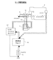
まず、本発明に係るハイブリッドシステムの一実施例としてのハイブリッドシステムIの構成について図1を用いて説明する。
ハイブリッドシステムIでは、エンジン2の出力軸部4の駆動を、エンジン2と電動機(モータ)として機能するモータジェネレータ40との両方により可能としている。出力軸部4から取り出された駆動力は、クラッチ部4aを介して出力部6に伝達され、動力伝達装置などを介して、作業機などの各種作業部、また、移動体などにおける走行車輪や船舶の水中推進用プロペラ等を駆動する。
First, the configuration of a hybrid system I as an embodiment of the hybrid system according to the present invention will be described with reference to FIG.
In the hybrid system I, the output shaft 4 of the
モータジェネレータ40は、エンジン2のクランク軸にその駆動軸が連結されたエンジン直結のホイールインモータであり、エンジン2の本体側と出力軸部4との間に介装されている。
モータジェネレータ40は、発電機またはモータとして機能し、インバータ部41の可変電圧可変周波数(以下、VVVF)インバータコンバータ42と接続されている。このVVVFインバータコンバータ42は、昇降圧チョッパ44を介して蓄電装置であるバッテリ14に接続されている。そして、モータジェネレータ40がモータとして機能する場合には、バッテリ14の給電電力がインバータ部41を介してモータジェネレータ40に供給される。一方、モータジェネレータ40が発電機として機能する場合には、エンジン2の駆動により該モータジェネレータ40で発電された電力がインバータ部41を介してバッテリ14に蓄電される。
The
The
インバータ部41は、VVVFインバータコンバータ42と昇降圧チョッパ44とから構成され、これらVVVFインバータコンバータ42及び昇降圧チョッパ44は、シーケンサ43を介してシステムコントローラ7と接続されている。このシーケンサ43を含むシステムコントローラ7が制御手段となる。システムコントローラ7は、制御対象の状態や、機関回転数や各種アクチュエータ等の外部からの信号に基づき、制御対象に与える操作やその順序などを制御する。そのため、システムコントローラ7とシーケンサ43との間では各種制御信号の通信が行われており、システムコントローラ7と、VVVFインバータコンバータ42及び昇降圧チョッパ44との信号のやりとりは、シーケンサ43を介して行われる。システムコントローラ7からVVVFインバータコンバータ42へは、起動信号や速度指令(モータ指令)などの信号が送信されており、システムコントローラ7と昇降圧チョッパ44との間では、起動信号や充電開始・充電電流に関する信号が通信されている。
また、インバータ部41には電圧センサ45が接続されており、この電圧センサ45によってインバータ部41のインバータ直流電圧やバッテリ電圧など各部の電圧を検出する。
The
In addition, a
モータジェネレータ40は、モータとしての機能(図2のM1・M2、図3及び図4参照)、及び発電機としての機能(図2のM3〜M5及び図5参照)を有しており、作業状況などに応じて各機能を発揮する。
つまり、ハイブリッドシステムIにおいては、モータジェネレータ40をモータとして作動させる場合には、VVVFインバータコンバータ42をインバータとして作動させるとともに、バッテリ14からの給電電力を、昇降圧チョッパ44により昇圧してモータジェネレータ40に供給し、モータジェネレータ40を発電機として作動させる場合には、VVVFインバータコンバータ42をコンバータとして作動させるとともに、モータジェネレータ40による発電電力を、昇降圧チョッパ44により降圧してバッテリ14に蓄電することを特徴としている。
The
In other words, in the hybrid system I, when the
すなわち、モータジェネレータ40がモータとして機能する場合には、バッテリ14からの給電電力がモータジェネレータ40に供給され、これにより、該モータジェネレータ40が作動する。バッテリ14から給電される直流電力は昇降圧チョッパ44を介してVVVFインバータコンバータ42に入力される。このとき、昇降圧チョッパ44は昇圧チョッパとして機能し、バッテリ14の給電電圧を所定の電圧に昇圧して、VVVFインバータコンバータ42に出力する。この際、VVVFインバータコンバータ42はインバータとして機能して、入力された直流電力を所定の電圧及び周波数の交流電力に変換し、この変換された交流電力をモータジェネレータ40に供給する。
That is, when the
また、VVVFインバータコンバータ42は、システムコントローラ7からの指令(速度指令・制御信号)に従い、モータとして作動するモータジェネレータ40の回転数及びトルクを制御する。前述したように、モータジェネレータ40の駆動軸はエンジン2のクランク軸と連結されており、モータジェネレータ40がモータとして作動することにより、該モータジェネレータ40の駆動力がエンジン2に伝達されて、後述するモータジェネレータ40によるスタータ機能及びアシスト機能が発揮される。
The
一方、モータジェネレータ40が発電機として機能する場合には、エンジン2の駆動力の一部または全部がモータジェネレータ40の作動に用いられ、このエンジン2からの駆動力によりモータジェネレータ40が作動して、発電が行われる。エンジン2の駆動によりモータジェネレータ40で発電された電力は、三相交流電力としてVVVFインバータコンバータ42に入力される。この際、VVVFインバータコンバータ42はコンバータとして機能し、モータジェネレータ40から入力された交流電力を整流・平滑化して直流電力に変換する。VVVFインバータコンバータ42によって変換された直流電力は、昇降圧チョッパ44を介してバッテリ14に入力され、これによりバッテリ14に蓄電される。このとき、昇降圧チョッパ44は降圧チョッパとして機能し、VVVFインバータコンバータ42から出力される直流電力を所定の電圧に降圧してバッテリ14に蓄電する。
On the other hand, when the
なお、以上に述べたように、VVVFインバータコンバータ42は、モータジェネレータ40がモータとして作動する場合には、バッテリ14から給電される直流電力を交流電力に変換するインバータとして機能し、モータジェネレータ40が発電機として作動する場合には、該モータジェネレータ40により発電された交流電力を直流電力に変換するコンバータとして機能する双方向電力変換装置となっている。
As described above, when the
このように、インバータ部41に昇降圧チョッパ44を使用することにより、バッテリ14からモータジェネレータ40へ供給される電圧を昇圧することができるため、バッテリ14からの出力(電力)が同じであれば、電圧が高くなった分、小電流化を図ることが可能となる(電力=電流×電圧)。これにより、昇降圧チョッパ44とVVVFインバータコンバータ42とを接続する配線、及びVVVFインバータコンバータ42とモータジェネレータ40とを接続する配線において、負荷をかけたとき流れる負荷電流の配線の抵抗によって失われる損失(銅損)を低減することができる。
Thus, since the voltage supplied from the
また、昇降圧チョッパ44を使用することにより、バッテリ14の小型化が図れる。つまり、モータとして駆動するモータジェネレータ40に供給する電圧は、高いほどモータジェネレータ40のモータ機能を発揮するためには有利であり、高い電圧で供給しようとすると、バッテリ14を大きくする必要があるが、昇降圧チョッパ44を使用することでバッテリ14から供給する電圧が低くても昇圧することが可能となるので、バッテリ14を大きくする必要がなくなるのである。これにより、本ハイブリッドシステムを搭載する機体における省スペース化、及び軽量化を図ることができる。
Further, by using the step-up / down
一方、エンジン2の駆動力(回転数)の調節は、操作部8に配設されるレギュレータレバー等の操作レバー9を操作することによって行われる。また、操作レバー9には、該操作レバー9のレバー位置を検出する位置センサ(図示略)が付設されており、この位置センサはシステムコントローラ7と接続されている。また、操作部8には、切り換え操作手段として、VVVF起動(回転数)指示スイッチ、CVCF(定電圧定周波数)起動スイッチ、昇降圧チョッパ起動スイッチ、蓄電開始スイッチ、蓄電電流指示スイッチ等の各種スイッチが配設されており、これらの各種スイッチはシステムコントローラ7と接続されている。
On the other hand, the adjustment of the driving force (rotation speed) of the
操作レバー9を操作すると、該操作レバー9のレバー位置が前記位置センサにより検出され、レバー位置に応じた信号がシステムコントローラ7に入力される。そして、システムコントローラ7は入力された信号に基づいてシフトアクチュエータ21及びスロットルアクチュエータ22を作動させる。
When the operation lever 9 is operated, the position of the operation lever 9 is detected by the position sensor, and a signal corresponding to the lever position is input to the system controller 7. Then, the system controller 7 operates the
シフトアクチュエータ21は、前記クラッチ部4aに接続されており、このシフトアクチュエータ21の作動によりクラッチ部4aのクラッチを作動させるように制御している。このようにしてクラッチを作動させることにより、出力軸部4から出力部6への駆動力の断接が行われる。また、シフトアクチュエータ21には、そのシフト位置を検出するポテンショメータ(図示略)が付設されている。ポテンショメータは、システムコントローラ7と接続されており、このポテンショメータにより検出されたシフト位置がシステムコントローラ7に入力される。
The
スロットルアクチュエータ22は、ラックピニオン式のDCモータ(スロットルモータ)により構成され、エンジン2のスロットルに接続されている。このスロットルアクチュエータ22の作動により、スロットル位置(スロットル開度)が変化する。このスロットル位置の変化によりエンジン2における燃料噴射量を調節して、エンジン2の駆動力(回転数)を調節可能としている。すなわち、スロットルアクチュエータ22は、エンジン2の回転数調節手段として機能する。そして、このスロットルアクチュエータ22を構成する前記DCモータは、システムコントローラ7に接続されており、該システムコントローラ7から送られる指令によって該DCモータが制御される。また、スロットルアクチュエータ22には、そのスロットル位置を検出するポテンショメータ(図示略)が付設されている。ポテンショメータは、システムコントローラ7と接続されており、このポテンショメータにより検出されたスロットルアクチュエータ22のスロットル位置がシステムコントローラ7に入力される。
このように、操作レバー9を操作して、そのレバー位置を調節することにより、エンジンの駆動力(回転数)の調節を行っている。ただし、後述するモータジェネレータ40の各制御が行われているときには、操作レバー9を操作することによる燃料噴射量の調節は行われない。つまり、モータジェネレータ40の制御は、操作レバー9のレバー位置から要求される燃料噴射量(指示回転数)が一定の状態で行われる。
The
In this manner, the operating force of the engine (rotational speed) is adjusted by operating the operating lever 9 and adjusting the lever position. However, when each control of the
以上のように構成されるハイブリッドシステムIにおいて、メインコントローラとしてのシステムコントローラ7は、次のように機能して本ハイブリッドシステムの制御を行う。
システムコントローラ7には、前述したように、操作部8における操作レバー9に付設される位置センサが接続され、また、シフトアクチュエータ21及びスロットルアクチュエータ22と、これらシフトアクチュエータ21及びスロットルアクチュエータ22にそれぞれ付設されるポテンショメータとが接続されている。
In the hybrid system I configured as described above, the system controller 7 as a main controller functions as follows to control the hybrid system.
As described above, the system controller 7 is connected to the position sensor attached to the operation lever 9 in the operation unit 8, and is attached to the
また、システムコントローラ7は、エンジン2と接続されており、該エンジン2からシステムコントローラ7に機関回転数が入力される。機関回転数は、エンジン2に付設される回転数センサ(図示略)により検出される。また、この回転センサにより検出される機関回転数は、VVVFインバータコンバータ42へも入力される。
The system controller 7 is connected to the
また、システムコントローラ7は、VVVFインバータコンバータ42と接続されており、システムコントローラ7は、VVVFインバータコンバータ42に対し、モータとしてのモータジェネレータ40の起動信号、及び予め決定される速度指令を送る。そして、VVVFインバータコンバータ42は、これらの信号に基づいて、モータとして作動する場合のモータジェネレータ40を制御する。一方、VVVFインバータコンバータ42は、システムコントローラ7へモータとして作動するモータジェネレータ40の回転数、トルク、及び交流電圧値などの信号を送る。モータジェネレータ40の回転数は、該モータジェネレータ40をモータとして作動させるときの回転数であり、前記回転センサにより検出される。つまり、モータジェネレータ40は、エンジン2のクランク軸と常時同期回転する構成としているため、回転数センサでモータジェネレータ40の回転数を検出することにより、エンジン2の回転数を知ることができる。よって、回転数センサは、機関回転数検出手段として機能することとなる。また、モータジェネレータ40の交流電圧は、該モータジェネレータ40をモータとして作動させるときにVVVFインバータコンバータ42から供給される交流電圧である。
The system controller 7 is connected to a
また、システムコントローラ7は昇降圧チョッパ44と接続されており、該システムコントローラ7は昇降圧チョッパ44に対し、起動信号、充電開始指示、充電電流(リミッタ)指示などを送り、昇降圧チョッパ44に接続されるバッテリ14を制御する。一方、昇降圧チョッパ44は、システムコントローラ7へバッテリ14の電圧、充放電電流などに関する信号を送る。システムコントローラ7は、前記電圧センサ45によって検出されるバッテリ14の電圧や、充放電電流を検出することによりバッテリ14の状態を知ることができる。
The system controller 7 is connected to the step-up / down
以上のように構成されるハイブリッドシステムIは、例えば、図2に示すような動作モードを備えており、各動作モードの動作状態におけるモータジェネレータ40の機能として、スタータ機能(図3参照)、アシスト機能(図4参照)、及び充電(発電)機能(図5参照)を有している。以下、各動作モードについて説明する。
The hybrid system I configured as described above has, for example, an operation mode as shown in FIG. 2, and the starter function (see FIG. 3), assist as the function of the
図3には、エンジン2起動(始動)時における電気回路の作動及び駆動力の伝達状態を示している。エンジン2は、バッテリ14からモータジェネレータ40に電力を供給して、該モータジェネレータ40をモータとして機能させることにより始動する。エンジン2を始動する際には、オペレータによる始動キーの操作により図示せぬリレーがオンされ、システムコントローラ7にエンジン始動の指令が入力される。システムコントローラ7は、VVVFインバータコンバータ42及び昇降圧チョッパ44にエンジン2の起動信号を送る。これにより、バッテリ14からの給電電力は、昇圧チョッパとして機能する昇降圧チョッパ44によって昇圧され、インバータとして機能するVVVFインバータコンバータ42によって所要の電圧及び周波数に変換されて、交流電力としてモータジェネレータ40に供給される。このようにして、モータジェネレータ40はモータとして作動する。このモータジェネレータ40の駆動軸は、前述したようにエンジン2のクランク軸と連結されており常時同期回転するため、モータジェネレータ40をモータとして駆動することにより、停止状態のエンジン2を始動させる。
FIG. 3 shows the operation of the electric circuit and the transmission state of the driving force when the
このように、モータとして作動するモータジェネレータ40にスタータ機能を兼ね備え、該モータジェネレータ40をエンジン2の起動時におけるスタータとして利用することにより、別途セルモータ(スタータモータ)等を設ける必要がなくなるので、省スペース化を図ることが可能となり、本ハイブリッドシステムが適用される機体において動力機関の搭載スペースを小さくすることができる。また、製造コストを低減することもできる。さらに、セルモータと比較して、エンジン起動時の騒音の低減、及び迅速な起動が可能となる。
Thus, since the
そして、エンジン2の起動終了後は、モータジェネレータ40を発電機として作動させ、常時バッテリ14への充電を行っており、「トルクアシスト要求」が発生した場合にのみ、モータジェネレータ40をモータとして作動させてトルクアシストを行う。なお、ここでの「トルクアシスト要求」とは、VVVFインバータコンバータ42によってモータジェネレータ40によるトルクアシストが必要と判断された場合に、該VVVFインバータコンバータ42からモータジェネレータ40へ送られる信号であり、この速度制御でのトルク指令を増加させる信号が相当する。
After the start of the
図4には、モータジェネレータ40によるトルクアシスト時における電気回路の作動及び駆動力の伝達状態を示している。なお、「トルクアシスト」とは、モータジェネレータ40をモータとして作動させ、このモータジェネレータ40によってエンジン2の駆動負荷の一部を賄うことを意味する。
FIG. 4 shows the operation of the electric circuit and the transmission state of the driving force at the time of torque assist by the
トルクアシストを行う際、システムコントローラ7は、VVVFインバータコンバータ42に対して予め決定される速度指令を出力し、昇降圧チョッパ44に対して起動信号を出力する。これにより、バッテリ14が放電状態となり、このバッテリ14からの給電電力は、昇圧チョッパとして機能する昇降圧チョッパ44によって昇圧され、インバータとして機能するVVVFインバータコンバータ42によって所要の電圧及び周波数に変換されて、交流電力としてモータジェネレータ40に供給される。このようにして、モータジェネレータ40が作動する。このトルクアシストを行う場合には、エンジン2に高い負荷がかかった場合や加速を行う場合等で、機関回転数が速度指令よりも低くなるような場合やトルク変動が生じた場合等において、モータジェネレータ40をモータとして駆動させる。この時エンジン2も駆動しており、モータジェネレータ40及びエンジン2の駆動力の和が出力軸部4の駆動力となる。
When performing torque assist, the system controller 7 outputs a predetermined speed command to the
このように、モータとして機能するモータジェネレータ40によって、トルクアシスト要求に従った適切なトルクアシストを行うことにより、エンジン2の出力が補われるので、エンジン2の小型化を図ることができる。また、このモータジェネレータ40による適切なトルクアシストによって、作業機などの加速性及び駆動性の向上が図れるとともに、燃費の向上、騒音の低減、及び排気色の改善を図ることが可能となる。
As described above, the
図5には、モータジェネレータ40により発電された電力により、バッテリ14の蓄電を行うとき、即ち、モータジェネレータ40を発電機として作動させてバッテリ14を充電するときの電気回路の作動及び駆動力の伝達状態を示している。このとき、エンジン2により出力軸部4及びモータジェネレータ40が駆動される。この状態においては、エンジン2にかかる負荷トルクが、該エンジン2の出力トルクよりも小さくなっており、このエンジン2の余剰トルク分をモータジェネレータ40による発電に用いている。つまり、エンジン2のみによって作業負荷に対応しており、このエンジン2の駆動によってモータジェネレータ40が発電機として作動して発電が行われ、このモータジェネレータ40による発電によってバッテリ14の蓄電が行われている状態である。
FIG. 5 shows the operation of the electric circuit and the driving force when the
発電機としてのモータジェネレータ40によってバッテリ14の蓄電を行う場合には、システムコントローラ7はVVVFインバータコンバータ42と昇降圧チョッパ44に充電開始指示を出力する。モータジェネレータ40による発電電力は、VVVFインバータコンバータ42により整流・平滑化されて直流電力に変換された後、昇降圧チョッパ44により降圧されて、バッテリ14に蓄電される。この際、VVVFインバータコンバータ42はコンバータとして機能する。
When the
また、ハイブリッドシステムIにおいては、このようにモータジェネレータ40を発電機として作動させて行うバッテリ14の蓄電には、該モータジェネレータ40の回生発電による蓄電を含むことを特徴としている。
この回生発電が発生する場合としては、例えば、本ハイブリッドシステムを油圧ショベル等の油圧建設機械に適用した場合には、ブーム・アーム・バケット等を有するフロント作業機のブーム下げ時や、このフロント作業機が取付けられる旋回体の旋回動作の制動時などである。
The hybrid system I is characterized in that the power storage of the
For example, when this regenerative power generation occurs, when this hybrid system is applied to a hydraulic construction machine such as a hydraulic excavator, the front work machine having a boom, an arm, a bucket, etc. For example, when the turning motion of the turning body to which the machine is mounted is braked.
このように、発電機として作動するモータジェネレータ40によるバッテリ14の蓄電に、該モータジェネレータ40による回生発電による蓄電を含むことにより、前述したようなブーム下げ時や旋回体の旋回動作の制動時の慣性エネルギーを回生電力として有効に取り出すことができ、モータジェネレータ40によるバッテリ14の充電効率の向上を図ることができる。
As described above, the
また、同じくモータジェネレータ40が発電機として作動している場合において、モータジェネレータ40に電気負荷がかかってない状態、即ち無電負荷の作動状態がある。この動作モードでは、VVVFインバータコンバータ42及び昇降圧チョッパ44は停止状態となっており、発電機としてのモータジェネレータ40は実質停止状態となり、エンジン2のみが単体で作動している状態となる。つまり、この動作モードにおいては、エンジン2の出力と該エンジン2に対する負荷とが均衡状態となっており、エンジン2のみによって効率の良い動作が行われている。なお、このモータジェネレータ40による発電によってバッテリ14が満充電状態となったときも、インバータ部41とバッテリ14との電位差が小さくなることでバッテリ14からの給電及びバッテリ14への充電は停止状態となり、エンジン2のみが単体で作動している状態となる。
Similarly, when the
以上の図3から図5を用いて説明したハイブリッドシステムIの有する機能は、図2に示す動作モードと次のように対応している。
図2に示すM1は、図3を用いて説明したモータとして機能するモータジェネレータ40によるスタータ機能が発揮される動作モードである。M2は、図4を用いて説明した同じくモータとして機能するモータジェネレータ40によるアシスト機能が発揮される動作モードである。M3からM5は、図5を用いて説明した発電機として機能するモータジェネレータ40による充電(発電)機能が発揮される動作モードであり、M3は、モータジェネレータ40が無電負荷の作動状態であり、エンジン2のみ単体で作動している動作モード、M4は、モータジェネレータ40による発電を行いつつエンジン2には作業負荷がかかっている状態で、モータジェネレータ40による回生発電が行われた場合は、この回生電力をバッテリ14に蓄電する動作モード、そしてM5は、M4の動作モードにおいてアイドル状態となったときの動作モードである。このアイドル状態においては、作業負荷はかかっておらず、モータジェネレータ40によるバッテリ14の充電のみが行われる。
The functions of the hybrid system I described with reference to FIGS. 3 to 5 correspond to the operation modes shown in FIG. 2 as follows.
M1 shown in FIG. 2 is an operation mode in which the starter function is exhibited by the
以上の説明のような、各モードにおいて好適に作動するハイブリッドシステムIを作業機などに適用することにより、前述した各作動時における効果に加え、一連の作動においてエンジン2にかかる負荷を一定にすることができ、負荷率の向上(後述する負荷平準化)を図ることができる。これにより、最大負荷時の出力を見込んで搭載されるエンジンの小型化を図ることができる。
また、低速域におけるエンジンの特性として、機関回転数が低いほどトルクが小さく不安定であること等があるが、モータジェネレータ40によるトルクアシストによって、この低速域におけるトルクの向上を図ることができる。これにより、燃費の向上や排気色の改善などの機関性能の向上を図ることができ、また、作業機として低速かつ正確な動作が要求される軽負荷の作業時での操作性を向上及び騒音の低減を図ることができる。
By applying the hybrid system I that operates suitably in each mode as described above to a work machine or the like, in addition to the effects at the time of each operation described above, the load applied to the
Further, as a characteristic of the engine in the low speed range, there is a case where the torque becomes smaller and unstable as the engine speed is lower. However, torque assist by the
また、このような構成のハイブリッドシステムIを小型の作業機などに適用する場合は、バッテリ14に出入力される電圧を昇降圧する昇降圧チョッパ44を使用しない構成とすることもできる。つまり、小型の作業機などのように、モータとして作動するモータジェネレータ40の出力が比較的小さくてもその作動に影響がないような場合、モータジェネレータ40のモータ機能を発揮するためには高い電圧は必要なく、昇降圧チョッパ44を使用せずとも本ハイブリッドシステムによる効果を得ることができる。
この場合、バッテリ14はVVVFインバータコンバータ42に直接接続され、バッテリ14のバッテリ容量はモータとして作動するモータジェネレータ40のモータ出力に対応したものとなる。
Further, when the hybrid system I having such a configuration is applied to a small working machine or the like, a configuration in which the step-up / step-down
In this case, the
このように、本ハイブリッドシステムを昇降圧チョッパ44を使用しない構成とすることにより、小型の作業機などにおいても、本ハイブリッドシステムによる効率の良い運転が可能となり、ランニングコストの低減効果を得ることが可能となる。
In this way, by adopting a configuration in which the hybrid system does not use the step-up / down
次に、本ハイブリッドシステムにおける、バッテリ14の充電状態に基づくエンジン2及びモータジェネレータ40の制御方法について説明する。
本制御方法は、バッテリ14の充電量が規定値を下回ると、モータジェネレータ40によるトルクアシストを行わず、通常、操作レバー9を操作することによって調節するエンジン2の回転数を、システムコントローラ7によって自動的に制御することで、機関出力(機関回転数)を一定に制御しようとするものである。すなわち、本制御方法は、バッテリ14の充電状態が、予め設定された規定値を下回った場合、モータジェネレータ40によるトルクアシストを行わず、スロットルアクチュエータ22を構成する前記DCモータを制御することによってエンジン2の回転数を調節して機関出力を一定に保持するように制御することを特徴としている。
Next, a control method of the
In this control method, when the charge amount of the
まず、バッテリ14の充電状態(以下、SOC(State of Charge))を演算する方法について説明する。
前述したように、エンジン2の駆動によりモータジェネレータ40にて発電された交流電力は、VVVFインバータコンバータ42にて整流・平滑化され直流電力に変換された後、昇降圧チョッパ44により所定の電圧に変圧されて、バッテリ14に蓄電される。また、バッテリ14からの給電電力によりモータジェネレータ40への電力供給を行い、該モータジェネレータ40を駆動可能としている。
First, a method for calculating the state of charge of the battery 14 (hereinafter, SOC (State of Charge)) will be described.
As described above, the AC power generated by the
バッテリ14のSOCは、バッテリ14の起電力とバッテリ14のバッテリ液(電解液)の比重との関係から、システムコントローラ7にて演算される。
具体的に説明すると、充放電中のバッテリ電圧(バッテリ14の端子電圧)Vbatは、次式(1)により表される。
Vbat=EO±ICD・RO ・・・(1)
この式を用いてバッテリ14のSOCを算出する。式(1)において、EOはバッテリ14の起電力(バッテリ開路電圧)、ICDはバッテリ14の充放電電流、ROはバッテリ14の内部抵抗である。バッテリ14の充放電電流ICDは、電流の向きによって充電電流または放電電流となり、式(1)においては、正(+)の場合には、充電電流であり、負(−)の場合には放電電流である。
The SOC of the
If it demonstrates concretely, the battery voltage (terminal voltage of the battery 14) Vbat during charging / discharging will be represented by following Formula (1).
Vbat = E O ± I CD · R O (1)
The SOC of the
電圧センサ45によって検出されるバッテリ電圧Vbat、及び充放電電流ICDは、昇降圧チョッパ44からシーケンサ43を介してシステムコントローラ7に送信される。システムコントローラ7は、入力されたバッテリ電圧Vbat及び充放電電流ICDに基づいてバッテリ14の内部抵抗ROを演算する。この算出された内部抵抗ROに基づき、式(1)からバッテリ開路電圧EOを演算する。そして、予めシステムコントローラ7には、図6に示すような、バッテリ開路電圧EOとバッテリ14のバッテリ液(電解液)の比重との関係と、図7に示すような、バッテリ液の比重とバッテリ14の放電深度(以下、DOD(Depth of Discharge))との関係が記憶されている。なお、システムコントローラ7には、バッテリ液とDODとの関係に代えて、バッテリ液とSOCとの関係を予め記憶させておいてもよい。このDODとSOCとは、ともにバッテリの充電状態を表す量であり、両者の間には、DOD+SOC=100%という関係がある。
The battery voltage Vbat and the charge / discharge current I CD detected by the
バッテリ開路電圧EOが分かると、システムコントローラ7は、バッテリ開路電圧EOとバッテリ液の比重との関係により、あるバッテリ温度(周囲温度)に対するバッテリの比重が算出される。そして、算出されたバッテリ液の比重から、バッテリ液の比重とDODとの関係によりバッテリ14のDODが演算され、このDODに対するバッテリ14のSOCが演算される。なお、このバッテリ14のSOCの演算方法は一例であり、システムコントローラ7によって一定以上の正確性を有するバッテリ14のSOCが随時演算できる方法であれば前記演算方法に限定されるものではない。
When the battery open circuit voltage E O is known, the system controller 7 calculates the specific gravity of the battery with respect to a certain battery temperature (ambient temperature) based on the relationship between the battery open circuit voltage E O and the specific gravity of the battery fluid. Then, the DOD of the
そして、システムコントローラ7にて、演算されたバッテリ14のSOCと、該システムコントローラ7に予め記憶されている規定値SOCminとが比較され、バッテリ14のSOCが規定値SOCminを下回っているか否かが判断される。ここで、バッテリ14のSOCが規定値SOCminを下回っている判断された場合、前述したエンジン2に一定以上高い作業負荷がかかった際のモータジェネレータ40によるトルクアシストを行わないようにし、その代わりに、エンジン2自体の出力を増加させることで、作業負荷に対するエンジン2の負荷平準化を行うように制御する。つまり、バッテリ14の充電量が低下し、モータジェネレータ40による十分なトルクアシストが行われない状態となった場合は、モータジェネレータ40によるトルクアシストを行わないようにすることでバッテリ14の放電を停止し、モータジェネレータ40によるトルクアシストの代わりに、エンジン2の燃料噴射量を調節するスロットルアクチュエータ22を制御することにより、機関出力(機関回転数)を一定に保持する。
Then, the calculated SOC of the
具体的にスロットルアクチュエータ22を制御することによるエンジン2の負荷平準化は次のようにして行われる。
スロットルアクチュエータ22は、前述したようにラックピニオン式のDCモータで構成されており、このスロットルアクチュエータ22のラックギアは、前述したメカニカルガバナのガバナレバーと接続されている。そして、このDCモータをシステムコントローラ7によって自動制御することにより、エンジン2の燃料噴射量を調節するとともに、機関回転数を調節する。
Specifically, the load leveling of the
As described above, the
すなわち、システムコントローラ7にて、前述のように演算されるバッテリ14のSOCが、規定値SOCminを下回った状態で、エンジン2に高い作業負荷がかかり、エンジン2の実回転数が速度指令よりも低くなった場合は、システムコントローラ7からスロットルアクチュエータ22のDCモータへ燃料噴射量を増やす方向にガバナレバーを作動させるように指令を送り、機関出力が一定となるように機関回転数を速度指令による指令値に保持する。そして、モータジェネレータ40による発電によってバッテリ14のSOCが規定値SOCminを下回った状態から、規定値SOCminを上回った場合は、通常のモータジェネレータ40によるトルクアシストの制御に移行する。
That is, in the state where the SOC of the
このように、バッテリ14の充電量が不足した状態ではモータジェネレータ40によるトルクアシストを行わず、エンジン2のスロットルアクチュエータ22を制御することによって機関出力を一定に保つようにすることで、エンジン2が長時間高負荷状態となってモータジェネレータ40によるトルクアシストが連続して行われた場合などのように、バッテリ14の充電量が不足した状態でも、作業負荷に対するエンジン2の特性(作業速度など)が変化することなく、作業中にバッテリ14の充電量不足にともなうモータジェネレータ40のトルクアシストのトルク不足による違和感(機関回転数の急激な低下など)を解消することができる。また、バッテリ14の過放電を防止することができるので、バッテリ14の過放電によるバッテリ性能の低下を防止して長寿命化を図ることができる。
In this way, when the charge amount of the
また、このようなシステムコントローラ7によるスロットルアクチュエータ22の自動制御を、バッテリ14による給電が終了した時から一定時間行うように制御することもできる。すなわち、この場合、モータジェネレータ40のトルクアシストにともなうバッテリ14からの給電が終了した時から、予め設定された時間が経過するまでは、モータジェネレータ40によるトルクアシストを行わず、スロットルアクチュエータ22を制御することによってエンジン2の回転数を調節して機関出力を一定に保持するように制御する。
Further, the automatic control of the
具体的には、エンジン2に高い作業負荷がかかってエンジン2の実回転数が速度指令よりも低くなると、モータジェネレータ40によるトルクアシストが行われるが、その後、作業負荷が解除されてエンジン2の実回転数が速度指令よりも高くなった時、即ちバッテリ14による給電が終了した時から、予め定められた時間が経過するまでは、モータジェネレータ40によるトルクアシストは行わず、前述のようにシステムコントローラ7によってスロットルアクチュエータ22の自動制御を行うことで、機関出力を一定に保ち、エンジン2の負荷平準化を図るのである。
Specifically, when a high work load is applied to the
そして、例えば、バッテリ14による給電が終了した時から一定時間スロットルアクチュエータ22の自動制御を行う場合を、本ハイブリッドシステムにおける「節電モード」とし、操作部8にこの「節電モード」のON/OFFを切り換えるスイッチ等を設け、本ハイブリッドシステムが適用される作業機などのオペレータによって任意に選択可能な構成とすることもできる。
For example, a case where the
このように制御することで、バッテリ14による給電が終了した時から一定時間は少なくともバッテリ14の放電が行われることはないので、バッテリ14の過放電を予め防止することが可能となる。また、このような制御が行われる場合を「節電モード」とし、切換え可能とすることによって、作業状態に即してバッテリ14の過放電を防止できるとともに、エンジン2の負荷平準化を図ることが可能となる。
By controlling in this way, since the
また、以上説明したような、ハイブリッドシステムIにおけるバッテリ14の充電状態に基づく制御は、図8に示すようなハイブリッドシステムIIにおいても行うことができる。
ハイブリッドシステムIIの構成は、ハイブリッドシステムIの構成を変更したものとなっており、その機能は略同様のものとなっている。すなわち、ハイブリッドシステムIIにおけるモータ5は、前述したハイブリッドシステムIにおいてモータとして作動する場合のモータジェネレータ40に相当し、ハイブリッドシステムIIにおけるオルタネータ11は、ハイブリッドシステムIにおいて発電機として作動する場合のモータジェネレータ40に相当する。また、ハイブリッドシステムIIは、後述するようにモータ駆動機能を有している。以下、ハイブリッドシステムIIの構成について図8を用いて説明する。なお、ハイブリッドシステムIと共通の装置などや同様の機能を有する装置などについては同符号を付して説明する。
The control based on the state of charge of the
The configuration of the hybrid system II is a change of the configuration of the hybrid system I, and the functions thereof are substantially the same. That is, the motor 5 in the hybrid system II corresponds to the
ハイブリッドシステムIIでは、エンジン2の出力軸部4の駆動を、エンジン2とモータ(電動機)5との両方により可能としている。出力軸部4から取り出された駆動力は、クラッチ部12を介して出力部6に伝達され、動力伝達装置などを介して、作業機などの各種作業部、また、移動体などにおける走行車輪や船舶の水中推進用プロペラ等を駆動する。
In the hybrid system II, the output shaft 4 of the
前記クラッチ部12においては、モータ5の出力軸部5aが、エンジン2のクランク軸に対して略垂直方向から、出力部6へ駆動力を伝達するように連結されている。つまり、クラッチ部12は、エンジン2及びモータ5からの駆動力を出力部6に伝達するとともに、エンジン2の出力軸部4と、モータ5の出力軸部5aと、出力部6とのそれぞれの連結・非連結(断接)の切り換えを行っている。このクラッチ部12の切換操作は、後述のシフトアクチュエータ21によって選択的に行われる。
In the
また、エンジン2内には、発電機としてのオルタネータ11が備えられており、該オルタネータ11は、昇降圧チョッパ44を介して蓄電装置であるバッテリ14と接続されている。昇降圧チョッパ44は、VVVFインバータコンバータ42と接続されており、該VVVFインバータコンバータ42は、前記モータ5と接続されている。オルタネータ11は、エンジン2の駆動にともなって発電し、該オルタネータ11で発電される電力は、昇降圧チョッパ44を介してバッテリ14に蓄電されるか、または、昇降圧チョッパ44を介することなくVVVFインバータコンバータ42に入力され、モータ5に供給される。なお、本実施例では、発電機としてオルタネータ11を用いて説明しているが、エンジン2の出力軸部4側に設けられるフライホイール型の発電機としてもよく、この場合は、発電機により発電された交流電力は整流器によって整流・平滑化され直流に変換される。
Further, an alternator 11 as a generator is provided in the
前記VVVFインバータコンバータ42及び昇降圧チョッパ44は、シーケンサ43を介してシステムコントローラ7と接続されている。このシーケンサ43を含むシステムコントローラ7が制御手段となる。システムコントローラ7は、制御対象の状態や、機関回転数や各種アクチュエータ等の外部からの信号に基づき、制御対象に与える操作やその順序などを制御する。そのため、システムコントローラ7とシーケンサ43との間では各種制御信号の通信が行われており、システムコントローラ7と、VVVFインバータコンバータ42及び昇降圧チョッパ44との信号のやりとりは、シーケンサ43を介して行われる。システムコントローラ7からVVVFインバータコンバータ42へは、起動信号や速度指令(モータ指令)などの信号が送信されており、システムコントローラ7と昇降圧チョッパ44との間では、起動信号や充電開始・充電電流に関する信号が通信されている。
また、VVVFインバータコンバータ42及び昇降圧チョッパ44からなるインバータ部には電圧センサ45が接続されており、この電圧センサ45によってインバータ部のインバータ直流電圧やバッテリ電圧など各部の電圧を検出する。
The
In addition, a
このような構成により、ハイブリッドシステムIIにおいては、オルタネータ11による発電電力を、昇降圧チョッパ44により降圧してバッテリ14に蓄電するか、またはインバータとして作動するVVVFインバータコンバータ42を介してモータ5に供給し、該モータ5を作動させる場合には、インバータとして作動するVVVFインバータコンバータ42を介して、オルタネータ11による発電電力、及び昇降圧チョッパ44により昇圧されるバッテリ14からの給電電力をモータ5に供給することを特徴としている。
With such a configuration, in the hybrid system II, the electric power generated by the alternator 11 is stepped down by the step-up / step-down
すなわち、モータ5を作動させる場合には、オルタネータ11により発電された電力、及びバッテリ14からの給電電力がモータ5に供給され、これにより、該モータ5が作動する。オルタネータ11により発電された直流電力は、昇降圧チョッパ44を介することなくVVVFインバータコンバータ42に入力される。また、バッテリ14から給電される直流電流は、昇降圧チョッパ44を介してVVVFインバータコンバータ42に入力される。このとき、昇降圧チョッパ44は昇圧チョッパとして機能し、オルタネータ11の発電電力及びバッテリ14の給電電圧を所定の電圧に昇圧して、VVVFインバータコンバータ42に出力する。これらの場合、VVVFインバータコンバータ42はインバータとして機能して、入力された直流電力を所定の電圧及び周波数の交流電力に変換し、この変換された交流電力をモータ5に供給する。
That is, when the motor 5 is operated, the electric power generated by the alternator 11 and the electric power supplied from the
また、VVVFインバータコンバータ42は、システムコントローラ7からの指令(速度指令・制御信号)に従い、モータ5の回転数及びトルクを制御する。モータ5の出力軸部5aは、前述のようにクラッチ部12にてエンジン2の出力軸部4と連結されており、モータ5が作動することにより、該モータ5の駆動力が出力部6に伝達されて、後述するハイブリッドシステムIIにおけるスタータ機能、アシスト機能、及びモータ駆動機能が発揮される。
The
そして、モータ5が回生状態になった場合は、該モータ5からの回生電力をバッテリ14に蓄電するようにしている。モータ5からの回生電力は、三相交流電力としてVVVFインバータコンバータ42に出力される。この際、VVVFインバータコンバータ42はコンバータとして機能して、モータ5から入力された交流電力を整流・平滑化して直流電力に変換する。VVVFインバータコンバータ42によって変換された直流電力は、昇降圧チョッパ44を介してバッテリ14に入力され、これによりバッテリ14に蓄電される。このとき、昇降圧チョッパ44は降圧チョッパとして機能し、VVVFインバータコンバータ42から入力される直流電力を所定の電圧に降圧してバッテリ14に蓄電する。この回生発電が発生する場合としては、例えば、本ハイブリッドシステムを油圧ショベル等の油圧建設機械に適用した場合には、ブーム・アーム・バケット等を有するフロント作業機のブーム下げ時や、このフロント作業機が取付けられる旋回体の旋回動作の制動時などである。
When the motor 5 is in a regenerative state, the regenerative power from the motor 5 is stored in the
一方、オルタネータ11を作動させる場合には、エンジン2の駆動力の一部または全部がオルタネータ11の作動に用いられ、このエンジン2からの駆動力によりオルタネータ11が作動して発電が行われる。エンジン2の駆動によりオルタネータ11で発電された直流電力は、昇降圧チョッパ44を介してバッテリ14に入力され、これによりバッテリ14に蓄電される。このとき、昇降圧チョッパ44は降圧チョッパとして機能し、VVVFインバータコンバータ42から出力される直流電力を所定の電圧に降圧してバッテリ14に蓄電する。また、このオルタネータ11により発電された直流電力は、前述したように、VVVFインバータコンバータ42を介してモータ5に供給される。
On the other hand, when the alternator 11 is operated, part or all of the driving force of the
なお、以上に述べたように、VVVFインバータコンバータ42は、モータ5を作動させる場合には、バッテリ14から給電される直流電力を交流電力に変換するインバータとして機能し、モータ5が回生状態になった場合には、該モータ5により発電された交流電力を直流電力に変換するコンバータとして機能する双方向電力変換装置となっている。
As described above, when operating the motor 5, the
このように、昇降圧チョッパ44を使用することにより、バッテリ14からモータ5へ供給される電圧を昇圧することができるため、バッテリ14からの出力(電力)が同じであれば、電圧が高くなった分、小電流化を図ることが可能となる(電力=電流×電圧)。これにより、昇降圧チョッパ44とVVVFインバータコンバータ42とを接続する配線、及びVVVFインバータコンバータ42とモータ5とを接続する配線において、負荷をかけたとき流れる負荷電流の配線の抵抗によって失われる損失(銅損)を低減することができる。
Thus, by using the step-up / step-down
また、昇降圧チョッパ44を使用することにより、バッテリ14の小型化が図れる。つまり、モータ5に供給する電圧は、高いほどモータ5の機能を発揮するためには有利であり、高い電圧で供給しようとすると、バッテリ14を大きくする必要があるが、昇降圧チョッパ44を使用することでバッテリ14から供給する電圧が低くても昇圧することが可能となるので、バッテリ14を大きくする必要がなくなるのである。これにより、本ハイブリッドシステムを搭載する機体における省スペース化、及び軽量化を図ることができる。
Further, by using the step-up / down
一方、エンジン2の駆動力(回転数)の調整は、操作部8に配設されるモード切換スイッチ(図示略)や、レギュレータレバー等の操作レバー9等を操作することによって行われる。また、操作レバー9には、該操作レバー9のレバー位置を検出する位置センサ(図示略)が付設されており、この位置センサはシステムコントローラ7と接続されている。また、操作部8には、切り換え操作手段として、VVVF起動(回転数)指示スイッチ、CVCF(定電圧定周波数)起動スイッチ、昇降圧チョッパ起動スイッチ、蓄電開始スイッチ、蓄電電流指示スイッチ等の各種スイッチが配設されており、これらの各種スイッチはシステムコントローラ7と接続されている。
On the other hand, the driving force (rotation speed) of the
前記モード切換スイッチは、システムコントローラ7と接続されており、該モード切換スイッチを操作すると、モード切換スイッチの切換位置に対応したモード信号がシステムコントローラ7に入力され、該システムコントローラ7により本ハイブリッドシステムのモード(駆動形態)が切り換えられて、各モードに対応した制御が行われるようにしている。
具体的には、図9に示すように、モード切換スイッチの操作によるモードの切り換えにより、出力部6をエンジン2により駆動しつつ、モータ5により駆動をアシストする「エンジン+モータ」モードと、出力部6をエンジン2のみにより駆動し、オルタネータ11の発電によるバッテリ14の充電をともなう「エンジン+発電機」モードと、クラッチ部12において、エンジン2の出力軸部4と出力部6とを非連結状態(クラッチ切状態)にして出力部6をモータ5のみにより駆動する「モータ」モードと、の3種類のパターンにより行うことを可能としている。
The mode changeover switch is connected to the system controller 7. When the mode changeover switch is operated, a mode signal corresponding to the changeover position of the mode changeover switch is input to the system controller 7, and the system controller 7 provides the hybrid system. These modes (drive modes) are switched so that control corresponding to each mode is performed.
Specifically, as shown in FIG. 9, an “engine + motor” mode that assists driving by the motor 5 while the
操作レバー9を操作すると、該操作レバー9のレバー位置が前記位置センサにより検出され、レバー位置に応じた信号がシステムコントローラ7に入力される。そして、システムコントローラ7は入力された信号に基づいてシフトアクチュエータ21及びスロットルアクチュエータ22を作動させる。
When the operation lever 9 is operated, the position of the operation lever 9 is detected by the position sensor, and a signal corresponding to the lever position is input to the system controller 7. Then, the system controller 7 operates the
シフトアクチュエータ21は、前記クラッチ部12に接続されており、このシフトアクチュエータ21の作動によりクラッチ部12のクラッチを作動させるように制御している。このようにしてクラッチを作動させることにより、エンジン2の出力軸部4から出力部6、モータ5の出力軸部5aと出力部6、出力軸部4と出力軸部5a、それぞれの駆動力の断接を選択的に行うことを可能としている。また、シフトアクチュエータ21には、そのシフト位置を検出するポテンショメータ(図示略)が付設されている。ポテンショメータは、システムコントローラ7と接続されており、このポテンショメータにより検出されたシフト位置がシステムコントローラ7に入力される。つまり、このポテンショメータが、クラッチ部12のクラッチの「入」「切」を検知する検知手段に相当する。
The
スロットルアクチュエータ22は、ラックピニオン式のDCモータ(スロットルモータ)により構成され、エンジン2のスロットルに接続されている。このスロットルアクチュエータ22の作動により、スロットル位置(スロットル開度)が変化する。このスロットル位置の変化によりエンジン2における燃料噴射量を調節して、エンジン2の駆動力(回転数)を調節可能としている。すなわち、スロットルアクチュエータ22は、エンジン2の回転数調節手段として機能する。そして、このスロットルアクチュエータ22を構成する前記DCモータは、システムコントローラ7に接続されており、該システムコントローラ7から送られる指令によって該DCモータが制御される。また、スロットルアクチュエータ22には、そのスロットル位置を検出するポテンショメータ(図示略)が付設されている。ポテンショメータは、システムコントローラ7と接続されており、このポテンショメータにより検出されたスロットルアクチュエータ22のスロットル位置がシステムコントローラ7に入力される。
このように、操作レバー9を操作して、そのレバー位置を調節することにより、エンジンの駆動力(回転数)の調整を行っている。ただし、後述するモータ5の各制御が行われているときには、操作レバー9を操作することによる燃料噴射量の調節は行われない。つまり、モータ5の制御は、操作レバー9のレバー位置から要求される燃料噴射量(指示回転数)が一定の状態で行われる。
The
As described above, the operating lever 9 is operated to adjust the position of the lever, thereby adjusting the driving force (rotation speed) of the engine. However, when each control of the motor 5 described later is being performed, the fuel injection amount is not adjusted by operating the operation lever 9. That is, the control of the motor 5 is performed in a state where the fuel injection amount (instructed rotational speed) required from the lever position of the operation lever 9 is constant.
以上のように構成されるハイブリッドシステムIIにおいて、メインコントローラとしてのシステムコントローラ7は、次のように機能して本ハイブリッドシステムの制御を行う。
システムコントローラ7には、前述したように、操作部8における操作レバー9に付設される位置センサが接続され、また、シフトアクチュエータ21及びスロットルアクチュエータ22と、これらシフトアクチュエータ21及びスロットルアクチュエータ22にそれぞれ付設される前述のポテンショメータとが接続されている。
In the hybrid system II configured as described above, the system controller 7 as a main controller functions as follows to control the hybrid system.
As described above, the system controller 7 is connected to the position sensor attached to the operation lever 9 in the operation unit 8, and is attached to the
また、システムコントローラ7は、エンジン2と接続されており、該エンジン2からシステムコントローラ7に機関回転数が入力される。機関回転数は、エンジン2に付設される回転数センサ(図示略)により検出される。また、この回転センサにより検出される機関回転数は、VVVFインバータコンバータ42へも入力される。
The system controller 7 is connected to the
また、システムコントローラ7は、VVVFインバータコンバータ42と接続されており、システムコントローラ7は、VVVFインバータコンバータ42に対し、モータ5の起動信号、及び予め決定される速度指令を送る。そして、VVVFインバータコンバータ42は、これらの信号に基づいてモータ5を制御する。一方、VVVFインバータコンバータ42は、システムコントローラ7へモータ5の回転数、トルク、及び交流電圧値などの信号を送る。モータ5の交流電圧は、該モータ5を作動させるときにVVVFインバータコンバータ42から供給される交流電圧である。
The system controller 7 is connected to the
また、システムコントローラ7は昇降圧チョッパ44と接続されており、該システムコントローラ7は昇降圧チョッパ44に対し、起動信号、充電開始指示、充電電流(リミッタ)指示などを送り、昇降圧チョッパ44に接続されるバッテリ14を制御する。一方、昇降圧チョッパ44は、システムコントローラ7へバッテリ14の電圧、充放電電流などに関する信号を送る。システムコントローラ7は、前記電圧センサ45によって検出されるバッテリ14の電圧や、充放電電流を検出することによりバッテリ14の状態を知ることができる。
The system controller 7 is connected to the step-up / down
以上のように構成されるハイブリッドシステムIIは、例えば、図9に示すような動作モーとを備えており、各動作モードの動作状態におけるモータ5及びオルタネータ11の機能として、スタータ機能(図10参照)、アシスト機能(図11参照)、充電(発電)機能(図12参照)、及びモータ駆動機能(図13参照)を有している。以下、各動作モードについて説明する。 The hybrid system II configured as described above includes, for example, an operation mode as shown in FIG. 9, and the starter function (see FIG. 10) is used as the function of the motor 5 and the alternator 11 in the operation state of each operation mode. ), An assist function (see FIG. 11), a charge (power generation) function (see FIG. 12), and a motor drive function (see FIG. 13). Hereinafter, each operation mode will be described.
図10には、エンジン2起動(始動)時における電気回路の作動及び駆動力の伝達状態を示している。エンジン2は、バッテリ14からモータ5に電力を供給して、該モータ5を機能させることにより始動する。エンジン2を始動する際には、オペレータによる始動キーの操作により図示せぬリレーがオンされ、システムコントローラ7にエンジン始動の指令が入力される。システムコントローラ7は、VVVFインバータコンバータ42及び昇降圧チョッパ44にエンジン2の起動信号を送る。これにより、バッテリ14からの給電電力は、昇圧チョッパとして機能する昇降圧チョッパ44によって昇圧され、インバータとして機能するVVVFインバータコンバータ42によって所要の電圧及び周波数に変換されて、交流電力としてモータ5に供給される。このようにして、モータ5が作動する。このモータ5の駆動軸は、クラッチ部12を介してエンジン2の出力軸部4と連結されており、該出力軸部4はエンジン2のクランク軸と常時同期回転するため、モータ5を駆動することにより、停止状態のエンジン2を始動させる。
FIG. 10 shows the operation of the electric circuit and the transmission state of the driving force when the
このように、トルクアシストを行うモータ5を、エンジン2の起動時におけるスタータとして利用することにより、別途セルモータ(スタータモータ)等を設ける必要がなくなり、省スペース化を図ることが可能となるので、本ハイブリッドシステムが適用される機体において動力機関の搭載スペースを小さくすることができる。また、製造コストを低減することもできる。
Thus, by using the motor 5 that performs torque assist as a starter when starting the
そして、エンジン2の起動終了後は、エンジン2が作動している状態ではオルタネータ11も作動状態となっており、常時バッテリ14への充電を行っており、「トルクアシスト要求」が発生した場合にのみ、モータ5を作動させてトルクアシストを行う。なお、ここでの「トルクアシスト要求」とは、VVVFインバータコンバータ42によってモータ5によるトルクアシストが必要と判断された場合に、該VVVFインバータコンバータ42からモータ5へ送られる信号であり、この速度制御でのトルク指令を増加させる信号が相当する。
After the start of the
図11には、モータ5によるトルクアシスト時における電気回路の作動及び駆動力の伝達状態を示している。なお、「トルクアシスト」とは、モータ5を作動させ、このモータ5によってエンジン2の駆動負荷の一部を賄うことを意味する。
FIG. 11 shows the operation of the electric circuit and the transmission state of the driving force during torque assist by the motor 5. “Torque assist” means that the motor 5 is operated and a part of the driving load of the
また、モータ5によって行われるトルクアシストは、エンジン2の駆動力に対するもの(エンジンアシスト)に限定されるものではない。すなわちこの場合、モータ5の出力軸部5aを、作業機などのクローラや走行車輪の車軸にクラッチ等を介して連結し、エンジン2自体はモータ5を作動させるための電力を発電する発電機としての機能を果たす構成となる。
Further, the torque assist performed by the motor 5 is not limited to that for the driving force of the engine 2 (engine assist). That is, in this case, the
モータ5によるトルクアシストは、前述したように、オルタネータ11による発電電力及びバッテリ14からの給電電力がモータ5に供給され、該モータ5が作動することによって行われる。このトルクアシストを行う場合には、エンジン2に高い負荷がかかった場合や加速を行う場合等で、機関回転数が速度指令よりも低くなるような場合やトルク変動が生じた場合等において、モータ5を駆動させる。この時エンジン2も駆動しており、モータ5及びエンジン2の駆動力の和が出力軸部4の駆動力となる。そして、モータ5によるトルクアシストは、通常、オルタネータ11による発電電力によって行われており、後述する「最大トルク要求が発生した場合」にのみ、オルタネータ11による発電電力に加え、バッテリ14からの給電電力がモータ5へ供給される。
As described above, torque assist by the motor 5 is performed when the power generated by the alternator 11 and the power supplied from the
トルクアシストを行う際、オルタネータ11による発電電力がモータ5に供給されるが、この場合、オルタネータ11からの発電電力は、昇降圧チョッパ44を介することなくVVVFインバータコンバータ42に入力される。そして、該VVVFインバータコンバータ42は、システムコントローラ7から送信される速度指令に従い、モータ5へトルク指令を送信してモータ5を制御する。つまり、モータ5は、システムコントローラ7からの速度指令に基づき、VVVFインバータコンバータ42によってその作動が制御される。
When torque assist is performed, the power generated by the alternator 11 is supplied to the motor 5. In this case, the power generated from the alternator 11 is input to the
具体的に、システムコントローラ7からVVVFインバータコンバータ42への速度指令の内容としては、エンジン2にかかる負荷が高い場合、VVVFインバータコンバータ42からモータ5へのトルク指令を増加させるようなものとなり、逆に、エンジン2にかかる負荷が低い場合は、VVVFインバータコンバータ42からモータ5へのトルク指令を減少させるようなものとなる。
Specifically, the content of the speed command from the system controller 7 to the
このように、モータ5によって、トルクアシスト要求に従った適切なトルクアシストを行うことにより、エンジン2の出力が補われるので、エンジン2の小型化を図ることができる。また、このモータ5による適切なトルクアシストによって、作業機などの加速性及び駆動性の向上が図れるとともに、燃費の向上、騒音の低減、及び排気色の改善を図ることが可能となる。
As described above, by performing appropriate torque assist in accordance with the torque assist request by the motor 5, the output of the
また、前述の「最大トルク要求が発生した場合」とは、エンジン2に対する負荷トルクが該エンジン2の有する機関最大トルクを上回った場合、またはこの機関最大トルクに一定以上近付いた場合が相当する。そして、この最大トルク要求が発生した場合は、オルタネータ11からモータへの電力供給に、バッテリ14からの電力供給が加わる。この場合、システムコントローラ7が、VVVFインバータコンバータ42に対して予め決定される速度指令を出力し、昇降圧チョッパ44に対して起動信号を出力する。これにより、バッテリ14から昇降圧チョッパ44に電力が供給されるようになり、このバッテリ14からの給電電力は、昇圧チョッパとして機能する昇降圧チョッパ44によって昇圧され、インバータとして機能するVVVFインバータコンバータ42によって所要の電圧及び周波数に変換されて、交流電力としてモータ5に供給される。
すなわち、ハイブリッドシステムIIにおける「エンジン+モータ」モードにおいて、モータ5によるトルクアシストが行われている場合、エンジン2にかかる負荷が比較的安定している状態では、モータ5に供給される電力はオルタネータ11による発電電力のみであり、負荷が高くなって最大トルク要求が発生した場合のみ、バッテリ14からの給電電力が加わる。
The above-mentioned “when the maximum torque request is generated” corresponds to the case where the load torque for the
That is, in the “engine + motor” mode in the hybrid system II, when torque assist is performed by the motor 5, the electric power supplied to the motor 5 is the alternator when the load applied to the
このように、モータ5によるトルクアシストが行われる場合、エンジン2にかかる負荷が比較的安定している通常状態では、オルタネータ11による発電電力の供給のみでモータ5が作動し、このオルタネータ11による発電電力は、昇降圧チョッパ44を介してバッテリ14に蓄電されることなく、オルタネータ11からVVVFインバータコンバータ42を介して直接モータ5に供給されるので、オルタネータ11によって発電される電力とモータ5に供給される電力との間のエネルギー効率、延いてはシステム効率の向上が図れる。そして、最大トルク要求が発生した場合のみ、モータ5への電力供給にバッテリ14からの給電電力の供給が加わるので、適切なトルクアシストが行われることとなる。これにより、最大負荷時の出力を見込んで搭載されるエンジン2の小型化が図れる。さらに、モータ5による適切なトルクアシストが行われることによって、燃費の向上、騒音の低減、及び排気色の改善を図ることが可能となる。
As described above, when torque assist is performed by the motor 5, in a normal state where the load applied to the
図12には、オルタネータ11により発電された電力により、バッテリ14の蓄電を行うときの電気回路の作動及び駆動力の伝達状態を示している。このとき、エンジン2により出力軸部4及びオルタネータ11が駆動される。この状態においては、エンジン2にかかる負荷トルクが、該エンジン2の出力トルクよりも小さくなっており、このエンジン2の余剰トルク分をオルタネータ11による発電に用いている。つまり、エンジン2のみによって作業負荷に対応しており、このエンジン2の駆動によってオルタネータ11が作動して発電が行われ、このオルタネータ11による発電によってバッテリ14の蓄電が行われている状態である。
オルタネータ11によってバッテリ14の蓄電を行う場合には、システムコントローラ7はVVVFインバータコンバータ42と昇降圧チョッパ44に充電開始指示を出力する。オルタネータ11によって発電された直流電力は、昇降圧チョッパ44にて降圧されて、バッテリ14に蓄電される。
FIG. 12 shows the operation of the electric circuit and the transmission state of the driving force when the
When the alternator 11 stores the
また、ハイブリッドシステムIIにおいては、オルタネータ11によって行われるバッテリ14の蓄電時に、モータ5による回生発電が行われた場合には、VVVFインバータコンバータ42をコンバータとして作動させるとともに、モータ5からの回生電力を、オルタネータ11による発電電力とともにバッテリ14に蓄電することを特徴としている。
この場合、モータ5の出力軸部5aは、クラッチ部12において連結状態となっており、回生時における出力部6またはエンジン2の出力軸部4の駆動によってモータ5が駆動され、該モータ5が発電機として作用して回生発電を行う。そして、このモータ5の回生発電による発電電力は、VVVFインバータコンバータ42により整流・平滑化されて直流電力に変換された後、昇降圧チョッパ44により降圧されて、バッテリ14に蓄電される。この際、VVVFインバータコンバータ42はコンバータとして機能する。
この回生発電が発生する場合としては、例えば、本ハイブリッドシステムを油圧ショベル等の油圧建設機械に適用した場合には、ブーム・アーム・バケット等を有するフロント作業機のブーム下げ時や、このフロント作業機が取付けられる旋回体の旋回動作の制動時などである。
Further, in the hybrid system II, when regenerative power generation by the motor 5 is performed when the
In this case, the
For example, when this regenerative power generation occurs, when this hybrid system is applied to a hydraulic construction machine such as a hydraulic excavator, the front work machine having a boom, an arm, a bucket, etc. For example, when the turning motion of the turning body to which the machine is mounted is braked.
このように、モータ5によるバッテリ14の蓄電に、該モータ5の回生発電による蓄電を含むことにより、前述したようなブーム下げ時や旋回体の旋回動作の制動時の慣性エネルギーを回生電力として有効に取り出すことができ、オルタネータ11によるバッテリ14への充電を補うことができる。
As described above, the power stored in the
また、同じくオルタネータ11による発電によってバッテリ14の蓄電が行われている場合において、オルタネータ11に電気負荷がかかってない状態、即ち無電負荷の作動状態がある。この動作モードでは、VVVFインバータコンバータ42及び昇降圧チョッパ44は停止状態となっており、発電機としてのオルタネータ11は実質停止状態となり、エンジン2のみが単体で作動している状態となる。つまり、この動作モードにおいては、エンジン2の出力と該エンジン2に対する負荷とが均衡状態となっており、エンジン2のみによって効率の良い動作が行われている。なお、このオルタネータ11による発電によってバッテリ14が満充電状態となったときも、インバータ部とバッテリ14との電位差が小さくなることでバッテリ14からの給電及びバッテリ14への充電は停止状態となり、エンジン2のみが単体で作動している状態となる。
Similarly, when the
図13には、モータ5の駆動力のみが出力部6に伝達されるときの電気回路の作動及び駆動力の伝達状態を示している。すなわち、クラッチ部12においてエンジン2の出力軸部4と出力部6とは非連結状態(クラッチ切状態)となっており、エンジン2の駆動力は出力部6へ伝達されず、モータ5の駆動力のみによって作業負荷に対応するモータ単独駆動状態としての「モータ」モードである。
FIG. 13 shows the operation of the electric circuit and the transmission state of the driving force when only the driving force of the motor 5 is transmitted to the
このモードにおいては、エンジン2が作動している場合、エンジン2の駆動力はオルタネータ11の作動にのみ用いられ、このオルタネータ11による発電電力がモータ5に供給され、該モータ5が作動する。そして、作業負荷が高くなったとき等は、オルタネータ11からの発電電力に加え、バッテリ14からの給電電力がモータ5へ供給される。
In this mode, when the
また、このモータ単独駆動状態において、エンジン2が停止している場合、モータ5に供給される電力は、バッテリ14からの給電電力のみであり、このバッテリ14からの給電電力によってモータ5が作動するモータ単独作動状態となる。この場合、バッテリ14からの給電電力は、昇降圧チョッパ44によって昇圧され、インバータとして機能するVVVFインバータコンバータ42を介してモータ5に供給される。
Further, when the
このように、出力部6への駆動力の供給がモータ5のみによって行われるモータ単独駆動状態を可能とすることにより、エンジン2の駆動力が全てオルタネータ11の作動に用いられるので、オルタネータ11による発電量を向上させるとともに、モータの特性としての低速域におけるトルクの安定性を有効に利用することができる。
また、このモータ単独駆動状態において、エンジン2の停止状態であるモータ単独作動状態では、モータ5のみが作動している状態で、作業機などの走行が可能となるので、エンジン2の作動による排気の防止や、騒音の低減及び燃費の向上を図ることができる。このモータ単独作動状態による騒音低減は、例えば、本ハイブリッドシステムを農作業機に適用した場合など、早朝時に、納屋などから実際に作業を行う圃場までの移動時にその効果を得ることができる。
As described above, since the driving force is supplied to the
Further, in this motor single drive state, in the motor single operation state in which the
以上の図10から図13を用いて説明したハイブリッドシステムIIの有する機能は、図9に示す動作モードと次のように対応している。
図9に示すm1は、図10を用いて説明したモータ5によるスタータ機能が発揮される動作モードである。m2及びm3は、図11を用いて説明したモータ5によるアシスト機能が発揮される動作モードであり、m2は、モータ5への電力の供給がオルタネータ11及びバッテリ14によって行われる動作モードで、m3は、モータ5への電力の供給がオルタネータ11のみによって行われる動作モードである。m4からm6は、図12を用いて説明したオルタネータ11による充電(発電)機能が発揮される動作モードであり、m4は、オルタネータ11が無電負荷の作動状態であり、エンジン2のみ単体で作動している動作モード、m5は、オルタネータ11による発電を行いつつエンジン2には作業負荷がかかっている状態で、モータ5による回生発電が行われた場合は、この回生電力をバッテリ14に蓄電する動作モード、そしてm6は、m5の動作モードにおいてアイドル状態となったときの動作モードである。このアイドル状態においては、作業負荷はかかっておらず、モータ5は停止状態で、オルタネータ11によるバッテリ14の充電のみが行われる。m7からm9は、図13を用いて説明したモータ5の駆動力のみが出力部6に伝達されるモータ駆動機能が発揮される動作モードであり、m7は、モータ5への電力供給がオルタネータ11及びバッテリ14によって行われる動作モードで、m9は、モータ5への電力供給がオルタネータ11のみによって行われる動作モード、m8は、エンジン2が停止状態のモータ単独作動状態の動作モードである。
The functions of the hybrid system II described with reference to FIGS. 10 to 13 correspond to the operation modes shown in FIG. 9 as follows.
M1 shown in FIG. 9 is an operation mode in which the starter function by the motor 5 described with reference to FIG. 10 is exhibited. m2 and m3 are operation modes in which the assist function by the motor 5 described with reference to FIG. 11 is exhibited, and m2 is an operation mode in which power supply to the motor 5 is performed by the alternator 11 and the
以上の説明のような、各モードにおいて好適に作動するハイブリッドシステムIIを作業機などに適用することにより、前述した各作動時における効果に加え、一連の作動においてエンジン2にかかる負荷を一定にすることができ、負荷率の向上(負荷平準化)を図ることができる。これにより、最大負荷時の出力を見込んで搭載されるエンジンの小型化を図ることができる。
また、低速域におけるエンジンの特性として、機関回転数が低いほどトルクが小さく不安定であること等があるが、モータ5によるトルクアシストによって、この低速域におけるトルクの向上を図ることができるので、燃費の向上や排気色の改善などの機関性能の向上を図ることができ、また、作業機として低速かつ正確な動作が要求される軽負荷の作業時での操作性を向上及び騒音の低減を図ることができる。
By applying the hybrid system II that operates suitably in each mode as described above to a work machine or the like, in addition to the effects at the time of each operation described above, the load applied to the
Further, as a characteristic of the engine in the low speed range, there is a case where the lower the engine speed is, the smaller the torque becomes and the more unstable, but the torque assist by the motor 5 can improve the torque in the low speed range. It is possible to improve engine performance such as improved fuel efficiency and exhaust color, and improve operability and reduce noise during light loads that require low speed and accurate operation as work equipment. Can be planned.
また、このような構成のハイブリッドシステムIIを小型の作業機などに適用する場合は、バッテリ14に出入力される電圧を昇降圧する昇降圧チョッパ44を使用しない構成とすることもできる。つまり、小型の作業機などのように、モータ5の出力が比較的小さくてもその作動に影響がないような場合、モータ5の機能を発揮するためには高い電圧は必要なく、昇降圧チョッパ44を使用せずとも本ハイブリッドシステムによる効果を得ることができる。
この場合、バッテリ14はVVVFインバータコンバータ42に直接接続され、バッテリ14のバッテリ容量はモータ5のモータ出力に対応したものとなる。
Further, when the hybrid system II having such a configuration is applied to a small working machine or the like, a configuration in which the step-up / step-down
In this case, the
このように、ハイブリッドシステムIIを昇降圧チョッパ44を使用しない構成とすることにより、小型の作業機などにおいても、本ハイブリッドシステムによる効率の良い運転が可能となり、ランニングコストの低減効果を得ることが可能となる。
In this way, by adopting a configuration in which the hybrid system II does not use the step-up / step-down
以上説明したハイブリッドシステムIIにおいても、前述したハイブリッドシステムIにおけるバッテリ14の充電状態に基づくエンジン2及びモータジェネレータ40の制御方法、即ちハイブリッドシステムIIにおけるバッテリ14の充電状態に基づくエンジン2及びモータ5の制御方法を同様にして行うことが可能であり、同様の効果を得ることができる。
Also in the hybrid system II described above, the control method of the
本発明の活用例として、建設機械における油圧ショベル等の駆動や、農作業機における各種作業部の駆動、また、船舶の水中推進用プロペラ等の駆動、その他の移動体(例えば、自動車等)における走行部や旋回部の駆動に広く適用可能である。 As examples of use of the present invention, driving of a hydraulic excavator or the like in a construction machine, driving of various working units in an agricultural working machine, driving of a propeller for underwater propulsion of a ship, traveling in another moving body (for example, an automobile, etc.) It can be widely applied to the driving of the part and the turning part.
2 エンジン
5 モータ
7 システムコントローラ
9 操作レバー
11 オルタネータ
12 クラッチ部
14 バッテリ
21 シフトアクチュエータ
22 スロットルアクチュエータ
40 モータジェネレータ
42 VVVFインバータコンバータ
44 昇降圧チョッパ
2 Engine 5 Motor 7 System Controller 9 Operation Lever 11
Claims (2)
前記制御手段は、前記蓄電装置の充電状態が、予め設定された規定値を下回った場合、前記モータによるトルクアシストを行わず、前記アクチュエータを制御することによってエンジンの回転数を調節して機関出力を一定に保持するように制御することを特徴とするハイブリッドシステムにおける制御方法。 An engine, a motor, a control means for controlling these, a generator, and a power storage device, and the indicated rotational speed of the engine by an operating lever for adjusting the rotational speed of the engine via an actuator is in a constant state, It is a hybrid system that attempts to keep the engine output constant by controlling charging of the power storage device by power generated by a generator and torque assist by the motor driven by power supplied from the power storage device. And
When the state of charge of the power storage device falls below a preset specified value, the control means adjusts the engine speed by controlling the actuator without performing torque assist by the motor, and outputs engine output Is controlled so as to be kept constant, and a control method in a hybrid system.
前記制御手段は、前記モータのトルクアシストにともなう前記蓄電装置からの給電が終了した時から、予め設定された時間が経過するまでは、前記モータによるトルクアシストを行わず、前記アクチュエータを制御することによってエンジンの回転数を調節して機関出力を一定に保持するように制御することを特徴とするハイブリッドシステムにおける制御方法。 An engine, a motor, a control means for controlling these, a generator, and a power storage device, and the indicated rotational speed of the engine by an operating lever for adjusting the rotational speed of the engine via an actuator is in a constant state, It is a hybrid system that attempts to keep the engine output constant by controlling charging of the power storage device by power generated by a generator and torque assist by the motor driven by power supplied from the power storage device. And
The control means controls the actuator without performing torque assist by the motor until a preset time elapses after power supply from the power storage device accompanying torque assist of the motor is completed. A control method in a hybrid system, characterized in that control is performed so as to maintain the engine output constant by adjusting the rotational speed of the engine.
Priority Applications (1)
| Application Number | Priority Date | Filing Date | Title |
|---|---|---|---|
| JP2004017502A JP2005207385A (en) | 2004-01-26 | 2004-01-26 | Control method in hybrid system |
Applications Claiming Priority (1)
| Application Number | Priority Date | Filing Date | Title |
|---|---|---|---|
| JP2004017502A JP2005207385A (en) | 2004-01-26 | 2004-01-26 | Control method in hybrid system |
Publications (1)
| Publication Number | Publication Date |
|---|---|
| JP2005207385A true JP2005207385A (en) | 2005-08-04 |
Family
ID=34902307
Family Applications (1)
| Application Number | Title | Priority Date | Filing Date |
|---|---|---|---|
| JP2004017502A Pending JP2005207385A (en) | 2004-01-26 | 2004-01-26 | Control method in hybrid system |
Country Status (1)
| Country | Link |
|---|---|
| JP (1) | JP2005207385A (en) |
Cited By (6)
| Publication number | Priority date | Publication date | Assignee | Title |
|---|---|---|---|---|
| JP2007327337A (en) * | 2006-06-06 | 2007-12-20 | Denso Corp | Vehicular power system |
| JP2010173599A (en) * | 2009-02-02 | 2010-08-12 | Sumitomo Heavy Ind Ltd | Control method for hybrid type operation machinery, and control method for servo control system |
| JP2014097766A (en) * | 2012-11-15 | 2014-05-29 | Shin Meiwa Ind Co Ltd | Hybrid electric work vehicle |
| JP2014189173A (en) * | 2013-03-27 | 2014-10-06 | Isuzu Motors Ltd | Hybrid electrically-driven vehicle |
| US9604388B2 (en) | 2012-02-14 | 2017-03-28 | International Paper Company | Process for making composite polymer |
| US10011266B2 (en) | 2016-01-07 | 2018-07-03 | Hyundai Motor Company | Method and controller for preventing over discharge of battery and hybrid vehicle thererby |
-
2004
- 2004-01-26 JP JP2004017502A patent/JP2005207385A/en active Pending
Cited By (7)
| Publication number | Priority date | Publication date | Assignee | Title |
|---|---|---|---|---|
| JP2007327337A (en) * | 2006-06-06 | 2007-12-20 | Denso Corp | Vehicular power system |
| JP4577274B2 (en) * | 2006-06-06 | 2010-11-10 | 株式会社デンソー | Vehicle power supply system |
| JP2010173599A (en) * | 2009-02-02 | 2010-08-12 | Sumitomo Heavy Ind Ltd | Control method for hybrid type operation machinery, and control method for servo control system |
| US9604388B2 (en) | 2012-02-14 | 2017-03-28 | International Paper Company | Process for making composite polymer |
| JP2014097766A (en) * | 2012-11-15 | 2014-05-29 | Shin Meiwa Ind Co Ltd | Hybrid electric work vehicle |
| JP2014189173A (en) * | 2013-03-27 | 2014-10-06 | Isuzu Motors Ltd | Hybrid electrically-driven vehicle |
| US10011266B2 (en) | 2016-01-07 | 2018-07-03 | Hyundai Motor Company | Method and controller for preventing over discharge of battery and hybrid vehicle thererby |
Similar Documents
| Publication | Publication Date | Title |
|---|---|---|
| JP5580307B2 (en) | Hybrid power supply device for crane and control method of hybrid power supply device for crane | |
| US8286741B2 (en) | Hybrid operating machine | |
| US8285434B2 (en) | Hybrid-type construction machine having an output condition calculating unit to calculate output conditions of an engine and an electric storage device | |
| WO2014073569A1 (en) | Work vehicle | |
| WO2012050010A1 (en) | Construction machine | |
| JP2005207386A (en) | Hybrid system | |
| US20100286856A1 (en) | Hybrid vehicle with a body builder equipment circuit and battery set | |
| JP3911517B2 (en) | Hybrid system | |
| JP4244963B2 (en) | Hybrid vehicle | |
| JP3708925B2 (en) | Hybrid system | |
| WO2016117547A1 (en) | Hybrid construction machine | |
| JP2005210869A (en) | Hybrid system | |
| WO2018143013A1 (en) | Power distribution system in moving body | |
| JP2005207385A (en) | Control method in hybrid system | |
| JP4157844B2 (en) | Control method of motor generator in hybrid system | |
| JP4399838B2 (en) | Operation control device for power supply device | |
| CN106605028B (en) | Hybrid construction machine | |
| WO2017110157A1 (en) | Hybrid-type working machine | |
| JP2006341708A (en) | Controller for hybrid vehicle | |
| JP2005210874A (en) | Method of controlling motor generator in hybrid system | |
| US11459077B2 (en) | Marine power supply system and method for power control in marine propulsion system | |
| JP2012025249A (en) | Hybrid type construction machine | |
| JP3950450B2 (en) | Engine control method in hybrid system | |
| JP4199136B2 (en) | Engine rotation control method in hybrid system | |
| JP2005207384A (en) | Engine speed control method in hybrid system |