JP2005202087A - Microscopic device, microscopic device control method and program - Google Patents
Microscopic device, microscopic device control method and program Download PDFInfo
- Publication number
- JP2005202087A JP2005202087A JP2004007521A JP2004007521A JP2005202087A JP 2005202087 A JP2005202087 A JP 2005202087A JP 2004007521 A JP2004007521 A JP 2004007521A JP 2004007521 A JP2004007521 A JP 2004007521A JP 2005202087 A JP2005202087 A JP 2005202087A
- Authority
- JP
- Japan
- Prior art keywords
- observation
- objective lens
- region
- target
- area
- Prior art date
- Legal status (The legal status is an assumption and is not a legal conclusion. Google has not performed a legal analysis and makes no representation as to the accuracy of the status listed.)
- Granted
Links
Images


Classifications
-
- G—PHYSICS
- G02—OPTICS
- G02B—OPTICAL ELEMENTS, SYSTEMS OR APPARATUS
- G02B21/00—Microscopes
- G02B21/36—Microscopes arranged for photographic purposes or projection purposes or digital imaging or video purposes including associated control and data processing arrangements
- G02B21/365—Control or image processing arrangements for digital or video microscopes
- G02B21/367—Control or image processing arrangements for digital or video microscopes providing an output produced by processing a plurality of individual source images, e.g. image tiling, montage, composite images, depth sectioning, image comparison
-
- G—PHYSICS
- G02—OPTICS
- G02B—OPTICAL ELEMENTS, SYSTEMS OR APPARATUS
- G02B21/00—Microscopes
- G02B21/0004—Microscopes specially adapted for specific applications
- G02B21/002—Scanning microscopes
- G02B21/0024—Confocal scanning microscopes (CSOMs) or confocal "macroscopes"; Accessories which are not restricted to use with CSOMs, e.g. sample holders
- G02B21/0036—Scanning details, e.g. scanning stages
Abstract
Description
本発明は、顕微鏡装置で用いられる技術に関し、特に、観察試料の時系列変化の観察を行うための技術に関する。 The present invention relates to a technique used in a microscope apparatus, and more particularly to a technique for observing a time-series change of an observation sample.
顕微鏡装置のひとつとして共焦点レーザ走査型顕微鏡装置が広く知られている。共焦点レーザ走査型顕微鏡装置は、レーザ光を対物レンズで微小なスポット光に絞り、このスポット光で観察試料上を走査したときに観察試料から到来する光を電気信号に変換し、この電気信号に基づいて観察試料についての画像を生成して画像モニタに表示させるというものである。 A confocal laser scanning microscope apparatus is widely known as one of the microscope apparatuses. A confocal laser scanning microscope device uses a lens to focus laser light into minute spot light, and when the spot light is scanned over the observation sample, it converts light coming from the observation sample into an electrical signal. Based on the above, an image of the observation sample is generated and displayed on the image monitor.
従来、このような顕微鏡装置は、細胞や組織の三次元的な構造や形態を観察するための手段として広く用いられてきたが、近年では、生細胞組織のダイナミクスを解析するための手段としても用いられるようになってきた。
例えば、特許文献1には、一定時間間隔をおいて光軸方向に亘る複数の試料断層像を共焦点顕微鏡装置で取得して時間間隔毎の試料断層像の差分画像を生成し、この差分画像から試料の擬似三次元像を作成して時間経過に応じて表示させることにより、試料の三次元的な時間変化を観察できるようにする技術が開示されている。
For example, in
細胞のダイナミクスな変化を時系列に観察する手法のひとつに、多点タイムラプス観察というものがある。多点タイムラプス観察は、観察試料上に設定された複数の観察領域の各々における時系列変化を観察するというものである。
例えば共焦点レーザ走査型顕微鏡装置を用いて多点タイムラプス観察を行う場合には、電動XYステージ装置と電動準焦部とを組み合わせた共焦点レーザ走査型顕微鏡装置へ観察試料における複数の注目領域を操作者が登録しておき、一定の時間間隔で、若しくは予め設定された回数だけ、その注目領域の各々についての画像の取得を繰り返すという実験が行われる。
One technique for observing dynamic changes in cells in time series is multipoint time-lapse observation. Multipoint time lapse observation is to observe a time-series change in each of a plurality of observation regions set on an observation sample.
For example, when performing multi-point time-lapse observation using a confocal laser scanning microscope apparatus, a plurality of regions of interest in an observation sample are transferred to a confocal laser scanning microscope apparatus that combines an electric XY stage apparatus and an electric focusing unit. An experiment is performed in which an operator registers and repeats acquisition of an image for each region of interest at a fixed time interval or a preset number of times.
この実験が開始されると、共焦点レーザ走査型顕微鏡装置は電動XYステージ装置と電動準焦部とを動作させて各注目領域の画像の取得を繰り返す。この画像の取得の繰り返しは操作者が注目領域を登録した順序で行われる。
注目領域の登録は試料上に散布されている細胞の中から操作者が注目領域を探索して行われるが、このとき操作者は電動XYステージ装置や電動準焦部の移動を考慮して探索・登録を行うことはない。そのため、実験を開始すると電動XYステージ装置や電動準焦部の動作に無駄のあることが多く、このような無駄によって実験の所要時間が長くなってしまうという問題を抱えていた。
When this experiment is started, the confocal laser scanning microscope apparatus operates the motorized XY stage device and the motorized focusing unit to repeatedly acquire images of each region of interest. This image acquisition is repeated in the order in which the operator registers the attention area.
The region of interest is registered by the operator searching for the region of interest from the cells dispersed on the sample. At this time, the operator searches considering the movement of the electric XY stage device and the electric focusing unit.・ Registration is not performed. For this reason, when the experiment is started, there are many cases where the operation of the electric XY stage device and the electric focusing unit is wasteful, and the time required for the experiment becomes longer due to such waste.
また、生細胞の時系列観察においては、細胞の形状変化や移動が予期しない範囲にまで及ぶことがあるために、細胞が当初設定していた観察視野から外れてしまうことがある。多点タイムラプス観察の実験中に細胞が観察視野から外れてしまった場合には、例えば新たな注目領域を共焦点レーザ走査型顕微鏡装置へ登録することによってその実験を継続し、その後の観察を可能とする。しかしながら、実験中にこのように追加登録された注目領域の画像の取得は、繰り返される一連の画像取得における最後に行われることとなる。このため、前述した場合と同様に電動XYステージ装置や電動準焦部に更なる無駄な移動を行わせる場合が多かった。 Further, in time-series observation of living cells, cell shape change and movement may extend to an unexpected range, and the cells may deviate from the observation field initially set. If cells are out of the field of view during a multipoint time-lapse observation experiment, the experiment can be continued by registering a new region of interest in the confocal laser scanning microscope, for example. And However, the acquisition of the image of the attention area additionally registered during the experiment is performed at the end of a series of repeated image acquisitions. For this reason, as in the case described above, there are many cases where the electric XY stage device and the electric focusing unit are caused to perform further useless movement.
本発明は上述した問題に鑑みてなされたものであり、その解決しようとする課題は、多点タイムラプス観察を行うための実験の所要時間を短縮することである。 The present invention has been made in view of the above-described problems, and the problem to be solved is to reduce the time required for an experiment for performing multipoint time-lapse observation.
本発明の態様のひとつである顕微鏡装置は、対物レンズの光軸に対して垂直な平面上で観察試料を移動させる平面移動手段と、当該観察試料に対してなされる複数の観察領域の各々の当該平面上における位置の設定を取得する観察領域位置設定取得手段と、当該対物レンズの合焦位置が位置している当該観察領域である対象観察領域の画像の取得の処理、若しくは当該対象観察領域への刺激の処理を行う対象観察領域処理手段と、当該対象観察領域と他の前記観察領域との間の距離を算出する算出手段と、当該平面移動手段を制御して当該観察試料を移動させて、当該観察領域のうち当該画像の取得の処理若しくは当該刺激の処理が未だ行われていないものであって且つ当該対象観察領域との間の当該距離が最短であるものを、当該対物レンズの合焦位置に位置させる平面移動制御手段と、を有することを特徴とするものである。 A microscope apparatus according to one aspect of the present invention includes a plane moving unit that moves an observation sample on a plane perpendicular to the optical axis of the objective lens, and each of a plurality of observation regions formed on the observation sample. Observation region position setting acquisition means for acquiring the position setting on the plane, and processing for acquiring an image of the target observation region that is the observation region where the focus position of the objective lens is located, or the target observation region Target observation area processing means for processing the stimulus to the eye, calculation means for calculating the distance between the target observation area and the other observation area, and the plane moving means to control the movement of the observation sample In the observation area, the image acquisition process or the stimulation process that has not yet been performed and the distance to the target observation area is the shortest is the objective lens. A planar movement control means for positioning the focus position, is characterized in that it has a.
この構成によれば、各観察領域を観察位置に順次位置させるために移動させる観察試料の移動量が短くなる。従って、それだけ平面移動手段の動作の無駄が削減される結果、実験の所要時間が短縮される。また、平面移動手段の動作時間が短くなるので、平面移動手段を動作させると生じる振動が観察試料へ及ぼす影響も低減される。 According to this configuration, the amount of movement of the observation sample to be moved in order to sequentially position each observation region at the observation position is shortened. Accordingly, as a result of reducing the waste of operation of the plane moving means, the time required for the experiment is shortened. In addition, since the operation time of the plane moving unit is shortened, the influence of vibration generated when the plane moving unit is operated on the observation sample is also reduced.
なお、上述した本発明に係る顕微鏡装置において、前述した観察領域から選ばれる最初に対象観察領域とするものである先頭観察領域の選択の設定を取得する選択取得手段と、平面移動手段を制御して前記観察試料を移動させ、当該先頭観察領域を前述した対物レンズの合焦位置へ位置させる初動制御手段と、いずれかの当該観察領域が当該対物レンズの合焦位置に位置したときに前述した画像の取得の処理若しくは前述した刺激の処理を前述した対象観察領域処理手段に行わせる対象観察領域処理制御手段と、を更に有し、前述した平面移動制御手段は、前述した対象観察領域処理手段による当該画像の取得の処理若しくは前記刺激の処理がひとつの当該対象観察領域に対して完了してから当該平面移動手段を制御する、ようにしてもよい。 In the above-described microscope apparatus according to the present invention, the selection acquisition unit that acquires the setting of selection of the first observation region that is the first target observation region selected from the above-described observation regions, and the plane moving unit are controlled. The initial movement control means for moving the observation sample and positioning the head observation area to the focus position of the objective lens described above, and when any of the observation areas is located at the focus position of the objective lens, A target observation region processing control unit that causes the above-described target observation region processing unit to perform image acquisition processing or the above-described stimulation processing, and the above-described plane movement control unit includes the above-described target observation region processing unit. The plane moving means may be controlled after the image acquisition process or the stimulus process is completed for one target observation region.
なお、このときに、所定の時間の経過を計時する計時手段を更に有し、前述した初動制御手段は、当該所定の時間が経過する度に前述した平面移動手段の制御を改めて開始し、前述した平面移動制御手段は、当該所定の時間が経過する度に全ての観察領域について前述した画像の取得の処理若しくは前述した刺激の処理が行われていないものとして前述した平面移動手段の制御を行う、ようにしてもよい。 In addition, at this time, it further has a timing means for timing the passage of a predetermined time, and the initial movement control means described above starts the control of the plane moving means anew every time the predetermined time passes, The plane movement control means performs the control of the plane movement means described above on the assumption that the above-described image acquisition process or the above-described stimulus process is not performed for all the observation areas every time the predetermined time elapses. You may do it.
更に、このときに、前述した初動制御手段による制御が開始された後に前述した観察試料に対してなされる新たな領域の前述した平面上の位置の設定を取得して当該領域を前述した観察領域とする観察領域位置設定追加取得手段を更に有する、ようにしてもよい。
また、前述した本発明に係る顕微鏡装置において、前述した対物レンズの焦点と前述した観察試料との間の相対的な位置関係を当該対物レンズの光軸方向に変化させる光軸方向移動手段と、前述した観察領域の各々における前述した光軸方向の位置の範囲の設定を取得する観察領域範囲取得手段と、前述した観察領域が前述した対物レンズの合焦位置に位置したときに当該光軸方向移動手段を制御して当該位置関係を変化させて、前述した観察試料に対する当該対物レンズの焦点の位置を、前述した対象観察領域について設定されている当該範囲を特定している一方の境界から他方の境界まで一定の向きに変化させる光軸方向移動制御手段と、を更に有し、前述した対象観察領域処理手段は、当該対象観察領域での当該観察試料に対する当該対物レンズの焦点の位置の変化量が所定の量に達する毎に、当該対象観察領域に対する前述した画像の取得の処理若しくは前述した刺激の処理を行う、ようにしてもよい。
Furthermore, at this time, after the control by the above-described initial motion control means is started, the setting of the position on the above-described plane of the new area made for the above-mentioned observation sample is acquired, and the area is referred to as the above-described observation area. It is also possible to further include an observation area position setting additional acquisition unit.
Further, in the above-described microscope apparatus according to the present invention, an optical axis direction moving means for changing a relative positional relationship between the focal point of the objective lens and the observation sample described above in the optical axis direction of the objective lens, Observation area range acquisition means for acquiring the setting of the position range in the optical axis direction in each of the observation areas described above, and the optical axis direction when the observation area is positioned at the in-focus position of the objective lens described above By controlling the moving means to change the positional relationship, the position of the focal point of the objective lens with respect to the observation sample described above is changed from one boundary to the other specifying the range set for the target observation region described above. And an optical axis direction movement control means for changing in a certain direction to the boundary of the target observation area processing means described above, the target observation area processing means described above for the observation sample in the target observation area For each change in position of the focal point of the object lens reaches a predetermined amount, performing the process of stimulated treated or the aforementioned acquisition of images described above with respect to the target observation area, it may be.
なお、このときに、前述した光軸方向移動制御手段による制御が終了したときにおける前述した観察試料に対する前述した対物レンズの焦点の位置である終了焦点位置を取得する終了時焦点位置取得手段を更に有し、当該光軸方向移動制御手段は、前述した対象観察領域について設定されている前述した範囲を特定している2つの境界のうち、当該終了時焦点位置取得手段によって直近に取得されていた当該終了焦点位置と近い方の境界から遠い方の境界へと前述した観察試料に対する当該対物レンズの焦点の位置を変化させる、ようにしてもよい。 At this time, the ending focal position acquisition means for acquiring the ending focal position, which is the focal position of the objective lens with respect to the observation sample when the control by the optical axis direction movement control means is completed, is further provided. The optical axis direction movement control means has been acquired most recently by the focus position acquisition means at the end of the two boundaries that specify the above-described range set for the target observation area. You may make it change the position of the focus of the said objective lens with respect to the observation sample mentioned above from the boundary nearer to the said end focus position to the boundary farther.
なお、以上の本発明に係る顕微鏡装置の各々において、前述した刺激の処理は、前述した対物レンズを介して前述した対象観察領域へレーザ光を照射する処理とすることができる。
また、本発明の別の態様のひとつである顕微鏡装置は、対物レンズの光軸に対して垂直な平面上で観察試料を移動させる平面移動手段と、当該観察試料に対してなされる複数の観察領域の各々の当該平面上における位置の設定を取得する観察領域位置設定取得手段と、当該対物レンズの合焦位置が位置している当該観察領域である対象観察領域の画像の取得の処理、若しくは当該対象観察領域への刺激の処理を行う対象観察領域処理手段と、当該対象観察領域と他の当該観察領域との間の距離を算出する算出手段と、当該観察領域の全てを当該対物レンズの合焦位置に順次位置させるべく当該観察試料の移動をさせるときに、当該距離に基づく順序であって当該移動の経路長を短くする当該順序で当該観察試料を移動させるように当該平面移動手段を制御する平面移動制御手段と、を有することを特徴とするものである。
In each of the above-described microscope apparatuses according to the present invention, the above-described stimulation process can be a process of irradiating the above-described target observation region with laser light via the above-described objective lens.
Further, a microscope apparatus according to another aspect of the present invention includes a plane moving unit that moves an observation sample on a plane perpendicular to the optical axis of the objective lens, and a plurality of observations performed on the observation sample. An observation region position setting acquisition unit that acquires setting of the position of each region on the plane, and processing for acquiring an image of the target observation region that is the observation region where the focus position of the objective lens is located, or Target observation area processing means for processing the stimulus to the target observation area, calculation means for calculating a distance between the target observation area and the other observation area, and all of the observation areas are When the observation sample is moved to be sequentially positioned at the in-focus position, the plane transfer is performed so that the observation sample is moved in the order based on the distance and in the order that shortens the path length of the movement. Is characterized in that it has a, a planar movement control means for controlling the means.
上述した構成によっても、前述した本発明に係る顕微鏡装置と同様の作用・効果を奏する結果、前述した課題が解決される。
また、本発明の更なる別の態様のひとつである顕微鏡装置の制御方法は、顕微鏡装置での観察対象である観察試料に対して複数設定される観察領域のうち当該顕微鏡装置に備えられている対物レンズの合焦位置が位置している観察領域である対象観察領域とその他の当該観察領域との間の距離を算出し、当該対物レンズの光軸に対して垂直な平面上で当該観察試料を移動させて、当該観察領域のうち当該観察領域の画像の取得の処理若しくは当該観察領域への刺激の処理が当該顕微鏡装置によって未だ行われていないものであって且つ当該対象観察領域との間の当該距離が最短であるものを、当該対物レンズの合焦位置に位置させる、ことを特徴とするものである。
Even with the above-described configuration, the above-described problems are solved as a result of the same operations and effects as the above-described microscope apparatus according to the present invention.
In addition, a method for controlling a microscope apparatus, which is another aspect of the present invention, is provided in the microscope apparatus among a plurality of observation regions set for an observation sample that is an observation target in the microscope apparatus. Calculate the distance between the target observation area, which is the observation area where the in-focus position of the objective lens is located, and other observation areas, and observe the observation sample on a plane perpendicular to the optical axis of the objective lens Of the observation area, the image acquisition process of the observation area or the stimulation process to the observation area has not yet been performed by the microscope apparatus, and between the observation area and the target observation area. The one with the shortest distance is positioned at the in-focus position of the objective lens.
こうすることにより、前述した本発明に係る顕微鏡装置と同様の作用・効果を奏する結果、前述した課題が解決される。
また、本発明の更なる別の態様のひとつであるプログラムは、顕微鏡装置での観察対象である観察試料に対して複数設定される観察領域のうち当該顕微鏡装置に備えられている対物レンズの合焦位置が位置している観察領域である対象観察領域とその他の当該観察領域との間の距離を算出する処理と、当該対物レンズの光軸に対して垂直な平面上で当該観察試料を移動させて、当該観察領域のうち当該観察領域の画像の取得の処理若しくは当該観察領域への刺激の処理が当該顕微鏡装置によって未だ行われていないものであって且つ当該対象観察領域との間の当該距離が最短であるものを、当該対物レンズの合焦位置に位置させる処理と、をコンピュータに行わせるためのものである。
By doing this, the above-described problems are solved as a result of the same operations and effects as the above-described microscope apparatus according to the present invention.
In addition, a program which is another aspect of the present invention is a program for an objective lens provided in a microscope device among a plurality of observation regions set for an observation sample which is an observation target in the microscope device. Processing to calculate the distance between the target observation area, which is the observation area where the focal position is located, and other observation areas, and to move the observation sample on a plane perpendicular to the optical axis of the objective lens In the observation area, the process of acquiring the image of the observation area or the process of stimulating the observation area has not yet been performed by the microscope apparatus, and the process between the observation area and the target observation area This is for causing the computer to perform the process of positioning the object with the shortest distance at the in-focus position of the objective lens.
コンピュータでこのプログラムを実行させることにより、前述した本発明に係る顕微鏡装置と同様の作用・効果を奏する結果、前述した課題が解決される。 By executing this program on a computer, the above-described problems are solved as a result of the same actions and effects as those of the microscope apparatus according to the present invention.
以上のように、本発明によれば、多点タイムラプス観察を行うための実験の所要時間が短縮されるという効果を奏する。 As described above, according to the present invention, there is an effect that the time required for an experiment for performing multipoint time-lapse observation is shortened.
以下、本発明の実施の形態を図面に基づいて説明する。
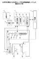
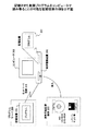
図1は、本発明を実施する共焦点レーザ走査型顕微鏡システムの構成を示している。
図1において、共焦点レーザ顕微鏡本体1にはコンピュータ2が接続されている。コンピュータ2には、レーザ光の光源であるレーザ装置4と画像表示のための画像モニタ5とが接続されている。
Hereinafter, embodiments of the present invention will be described with reference to the drawings.
FIG. 1 shows the configuration of a confocal laser scanning microscope system embodying the present invention.
In FIG. 1, a
レーザ装置4から共焦点レーザ走査型顕微鏡本体1へ入射したレーザ光は励起用ダイクロイックミラー102によって反射され、走査ユニット104に入射する。走査ユニット104は、X軸方向走査用のガルバノメータミラーとY軸方向走査用のガルバノメータミラーとを有しており、コンピュータ2から送られてくる走査制御信号に従い、レボルバ105に取り付けられている対物レンズ106へのレーザ光の光路に対して垂直な平面上で直交するX軸方向(主走査方向)とY軸方向(副走査方向)に対しレーザ光をXY走査させる。この二次元走査におけるX軸方向の走査による1ラインの走査が完了する毎に、走査ユニット104は走査制御終了信号をコンピュータ2へ出力する。
The laser light incident on the confocal laser scanning microscope
XY走査がされているレーザ光は、対物レンズ106を介し、ステージ107上に載置されている観察試料108上へ、スポット光として照射される。このスポット光の照射によって観察試料108から対物レンズ106に到来する光(例えば、反射光、または観察試料108から発生した蛍光)は共焦点レーザ走査型顕微鏡本体1内の入射光路へ戻されるが、励起用ダイクロイックミラー102を透過してダイクロイックミラー103で反射され、レンズ109で集光される。レンズ109の集光位置にはコンフォーカルアパーチャ110が配置されており、共焦点光学系が構成されている。
The laser light that has been subjected to XY scanning is irradiated as spot light onto the
コンフォーカルアパーチャ110を通過した光は、バリアフィルタ111に入射する。バリアフィルタ111は、入射した光のうち観察者の所望する波長のもののみを通過させてフォトマルチプライヤ等の光電変換器101に入力させる。光電変換器101は入力した光をアナログ電気信号へ変換する。コンピュータ2に設置されているA/D変換器2bがこの電気信号をアナログ−デジタル変換することにより、光電変換器101は入力した光の光量に応じたデジタルデータが得られる。
The light that has passed through the
このデジタルデータはメモリ2cに記憶される。走査ユニット104がXY走査を1周期行ってメモリ2cに蓄積されたデータに基づいて観察試料108に関する1枚の画像が生成され、画像モニタ5に表示される。
ステージ107は、レボルバ105に取り付けられている対物レンズ106の光軸に対して垂直な平面(XY平面と称することとする)上で直交するX軸方向とY軸方向とに移動可能な電動XYステージ装置である。なお、走査ユニット104がレーザ光をX軸方向に走査したときにはステージ107でのX軸方向にスポット光が走査され、レーザ光をY軸方向に走査したときにはステージ107でのY軸方向にスポット光が走査されるものとする。
This digital data is stored in the
The
また、共焦点レーザ走査型顕微鏡本体1の内部若しくは外部には不図示のZモータが電動準焦部として備えられている。この電動準焦部を動作させることにより、レボルバ105若しくはステージ107を、対物レンズ106の光軸方向であるZ軸方向に移動させることができる。
Further, a Z motor (not shown) is provided as an electric focusing unit inside or outside the confocal laser scanning microscope
これらの電動XYステージ装置及び電動準焦部によるXYZ各軸方向の移動は、コンピュータ2によって制御される。
コンピュータ2に接続されている操作パネル3は、キーボードに加え、トラックボールやジョイスティック、あるいはマウス等のポインティングデバイスを有しており、観察者が操作することによって、レーザ光の走査開始命令、画像取得命令、光電変換器101の感度の調整命令などをコンピュータ2に対して行う。
The movement in the X, Y, and Z axis directions by the electric XY stage device and the electric focusing unit is controlled by the
The
コンピュータ2は、CPU(中央演算装置)を備えている計算・処理部2aに制御プログラム2dを実行させることによって図1に示したシステム全体の制御を司るものである。特に、操作パネル3から走査開始命令が入力されたときには、コンピュータ2は、走査制御信号を走査ユニット104へ出力し、光電変換器101から出力されるアナログ信号をA/D変換器2bでデジタルデータに変換してメモリ2cへ転送し、観察試料108に関する画像を走査指示のためのメニュー画面とともに画像モニタ5に表示させる。また、コンピュータ2は、走査パネル3から感度の調整命令が入力されたときには、光電変換器101に関する印加電圧、アンプゲイン、オフセット等の設定を共焦点レーザ走査型顕微鏡本体1に対して行う。この他、走査ユニット104の動作制御、レーザ装置4からのレーザ光の出射、以前にメモリ2cに記憶させたデータに基づく画像の画像モニタ5への表示制御なども、操作パネル3からの所定の命令の入力に応じてコンピュータ2により行われる。
The
また、計算・処理部2aは、観察者の所望する観察領域についての情報、例えばその位置を特定する座標(例えば当該観察領域の中心位置の座標)を示す情報を、前述した対物レンズ106の光軸を基準としたX、Y、Zの座標値でメモリ2cに記憶させ、更に、その観察領域での画像走査条件をメモリ2cに記憶させる。ここで、画像走査条件とは、光電変換器101に関する印加電圧、アンプゲイン、オフセット、または、その観察領域におけるZ軸方向のスライス数(Z座標を一定間隔で変化させて取得するその観察領域に関する画像の枚数)や各スライス間のステップサイズ(一定間隔でZ座標を変化させてその観察領域に関する画像を取得する際におけるZ座標の変化幅)など、観察者の所望する画像を取得するために必要な条件のことである。
In addition, the calculation /
また、計算・処理部2aは、コンピュータ2に設けられている記憶装置(不図示)に核のされている制御プログラム2dを実行することにより、メモリ2cに記憶されている観察領域の位置情報に基づき、共焦点レーザ走査型顕微鏡本体1の現在の状態において対物レンズ106の合焦位置に位置している観察領域から全ての観察領域を経由して元の観察領域へ位置させるまでの移動経路が効率的となる登録位置の経由順序の決定が行われる。
Further, the calculation /
更に、計算・処理部2aは、制御プログラム2dを実行することにより、決定された経由順序に従った移動経路で観察試料108を移動させるべく、電動XYステージ装置及び電動準焦部の動作を制御する。
次に、図1に示したシステムにおける計算・処理部2aによって行われる、前述した観察領域の経由順序の決定の手法について説明する。
Further, the calculation /
Next, a description will be given of the above-described method for determining the order of passing through the observation area, which is performed by the calculation /
まず、観察者は、例えば共焦点レーザ走査型顕微鏡本体1に備えられている接眼レンズ(不図示)を通して観察試料108の拡大像を観察する。ここで、電動XYステージ装置や電動準焦部を動作させて観察試料108上に複数の観察領域を設定してコンピュータ2へその位置を登録する。
First, the observer observes an enlarged image of the
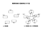
図2は、観察領域の登録例を示している。ここで、図2(a)は観察領域の登録順を示しており、No.1、No.2、No.3、No.4、No.5の順に登録されたものとする。
このような順序で観察領域の登録が行われた場合に、多点タイムラプス観察のための実験における観察領域の画像の取得順をこの登録順に従って行うと、図2(b)に矢印で示すような、(1)、(2)、(3)、(4)、(5)の順でその取得が行われる。従来の顕微鏡装置でこの実験を行うと、まさにこのような順序で画像の取得が行われていた。
FIG. 2 shows an example of registration of observation regions. Here, FIG. 2A shows the registration order of observation regions. 1, no. 2, no. 3, no. 4, no. It is assumed that they are registered in the order of 5.
When the observation areas are registered in this order, if the order of obtaining the images of the observation areas in the experiment for multi-point time lapse observation is performed according to the registration order, as shown by an arrow in FIG. The acquisition is performed in the order of (1), (2), (3), (4), and (5). When this experiment was performed with a conventional microscope apparatus, images were acquired in exactly this order.
これに対し、本実施形態に係る手法では、以下に示す手法を採って観察領域の観察順(画像の取得順)を決定する。
まず、登録されている観察領域のうち観察を最初に行うもの(「先頭観察領域」と称することとする)を観察者が選択し、操作パネル3を操作してコンピュータ2へ設定する。なお、先頭観察領域を観察者が選択する代わりに、例えば、XY平面で対物レンズ106の現在の合焦位置(以下、単に「観察位置」と称することとする)に最も近い観察領域や、閉じたXY平面における特定の隅に最も近い観察領域などを、制御プログラムの実行によって計算・処理部2aが自動的に先頭観察領域として選択するようにしてもよい。
On the other hand, in the method according to the present embodiment, the observation order (image acquisition order) of the observation region is determined by using the following method.
First, the observer selects the first observation area to be observed (referred to as “first observation area”) from among the registered observation areas, and operates the
今、図2(a)に示す登録順の例において、No.1の観察領域が先頭観察領域として設定されたとする。
次に、計算・処理部2aは、先頭観察領域とその他の観察領域との間のXY平面上での距離を算出して比較し、先頭観察領域からの距離が最短である観察領域を選択する。
Now, in the example of the registration order shown in FIG. Assume that one observation area is set as the head observation area.
Next, the calculation /
図2(a)の観察領域の例では、図3(a)に示すように、No.1−No.2間、No.1−No.3間、No.1−No.4間、No.1−No.5間の4つの距離を算出し、このうち距離が最短であるのはNo.1−No.4間であるので、No.1の観察領域に続いてNo.4がこの距離に基づいて選択される。 In the example of the observation region in FIG. 2A, as shown in FIG. 1-No. No. 2 1-No. 3 and No. 1-No. 4 No. 1-No. 4 distances between 5 are calculated, and the shortest distance is No. 1-No. No. 4, so no. No. 1 followed by No. 1 4 is selected based on this distance.
なお、ここで、比較した距離が最短で等しい場合には、例えば前述した登録順に従い、先に登録された観察領域を選択するようにする。
ここで、「対象観察領域」という語を定義する。対象観察領域とは、ある観察順において観察の対象とされる観察領域を指す。上述した図2(a)の例では、実験を開始したときに対物レンズ106の合焦位置に最初に位置させることとなる先頭の対象観察領域はNo.1の観察領域であり、二番目の対象観察領域はNo.4の観察領域となる。
Here, when the compared distances are the shortest and the same, for example, the previously registered observation region is selected according to the above-described registration order.
Here, the term “target observation area” is defined. The target observation area refers to an observation area that is an observation target in a certain observation order. In the example of FIG. 2A described above, the first target observation region that is first positioned at the in-focus position of the
次に、計算・処理部2aは、上述したようにして選択された対象観察領域に続く次の対象観察領域の選択を行う。このときも、上述したものと同様に、現在の観察順での対象観察領域と、未だ順序が確定していない残りの観察領域との間のXY平面上での距離を算出して比較し、この対象観察領域との間の距離が最短である観察領域を次の対象観察領域として選択する。
Next, the calculation /
図3(a)の例においてNo.1の先頭観察領域に続いてNo.4の観察領域が対象観察領域として選択されたときには、図3(b)に示すように、No.4−No.2間、No.4−No.3間、No.4−No.5間の3つの距離を算出し、このうち距離が最短であるのはNo.4−No.2間であるので、No.4の観察領域に続いてNo.2が次の対象観察領域としてこの距離に基づいて選択される。 In the example of FIG. No. 1 followed by the first observation area. When the observation area No. 4 is selected as the target observation area, as shown in FIG. 4-No. No. 2 4-No. 3 and No. 4-No. The three distances between the five are calculated. 4-No. Since it is between 2, no. No. 4 followed by the observation area. 2 is selected as the next target observation area based on this distance.
以降、計算・処理部2aは、上述した観察領域の選択を繰り返すことによって、全ての観察領域の観察順を決定する。
図2(a)に示した観察領域の例に対して上述したようにして決定された観察領域の観察順を図4に示す。このように、図2(a)の例からは、No.1→No.4→No.2→No.5→No.3の順序が決定される。
Thereafter, the calculation /
FIG. 4 shows the observation order of the observation regions determined as described above with respect to the example of the observation region shown in FIG. Thus, from the example of FIG. 1 → No. 4 → No. 2 → No. 5 → No. The order of 3 is determined.
以上のように、観察領域のうち観察(画像の取得)が未だ行われていないものであって且つ対象観察領域との間の距離が最短であるものを先頭観察領域から順次選択して観察順序が決定される。そして、この観察順に従って全ての観察領域を観察位置に順次位置させて行う観察を所定の時間間隔をおいて繰り返すことにより、多点タイムラプス観察が可能となる。 As described above, the observation order in which the observation (acquisition of images) has not yet been performed and the distance to the target observation area is the shortest is sequentially selected from the first observation area. Is determined. Then, by repeating the observation performed by sequentially locating all the observation regions at the observation position according to this observation order, a multipoint time-lapse observation can be performed.
ここで、図2(b)と図4とを比較すれば明らかなように、本実施形態に係る手法を採ることにより、各観察領域を観察位置に順次位置させるために移動させる観察試料108の移動量は短くなる。従って、それだけ電動XYステージ装置や電動準焦部の動作の無駄が削減される結果、実験の所要時間が短縮される。また、電動XYステージ装置や電動準焦部の動作時間が短くなるので、それだけ電動XYステージ装置や電動準焦部を動作させると生じる振動が観察試料108へ及ぼす影響も低減される。
Here, as apparent from a comparison between FIG. 2B and FIG. 4, by using the method according to the present embodiment, the
次に図5及び図6について説明する。これらの図は、コンピュータ2の計算・処理部2aによって行われる制御処理の処理内容をフローチャートで示したものである。なお、同図に示す処理は、前述した制御プログラム2dを計算・処理部2aで実行させることによって実現される。
Next, FIGS. 5 and 6 will be described. These figures show the processing contents of the control processing performed by the calculation /
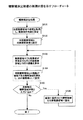
まず、図5のフローチャートについて説明する。同図は観察順決定処理の処理内容を示している。この処理は、上述した本実施形態に係る手法に従って各観察領域の観察順を決定するための処理である。なお、この処理は、後述する顕微鏡制御処理において実行される。 First, the flowchart of FIG. 5 will be described. The figure shows the processing contents of the observation order determination processing. This process is a process for determining the observation order of each observation region according to the method according to the present embodiment described above. This process is executed in a microscope control process described later.
なお、ここでは、この処理の実行開始前に、各観察領域及びその位置に関する情報がコンピュータ2のメモリ2cに既に記憶されているものとする。
まず、S101では、観察者若しくは計算・処理部2a自身によって各観察領域から選択され設定された先頭観察領域を取得し、取得された先頭観察領域を観察順の先頭として設定する処理が行われ、続くS102では、この先頭観察領域を現在の対象観察領域として設定する処理が行われる。
Here, it is assumed that information regarding each observation region and its position is already stored in the
First, in S101, a processing is performed to acquire the first observation region selected and set from each observation region by the observer or the calculation /
S103では、メモリ2cに記憶されている観察領域のうち未だ観察順の設定されていないものと直近に観察順が設定された対象観察領域との間のXY平面上での距離を各々算出する処理が行われ、続くS104において、そのうち対象観察領域との間の距離が最短である観察領域を選択し、選択された観察領域を次の観察順として設定する処理が行われる。
In S103, a process of calculating the distances on the XY plane between the observation areas stored in the
S105では、メモリ2cに記憶されている観察領域のうち未だ観察順の設定されていないものが未だ残されているか否かを判定する処理が行われ、未だ残されていると判定した(判定結果がYes)ならば、S106において、前述したS104の処理が直近に実行されたときに観察順が設定された観察領域を対象観察領域として設定する処理が行われ、その後はS103へと処理を戻して上述した処理が繰り返される。一方、S105の判定処理において、観察順の設定されていない観察領域が残されていないと判定した(判定結果がNo)ならば、全ての観察領域について観察順が決定されたとみなし、この観察順処理を終了する。
In S105, a process of determining whether or not an observation area stored in the
以上までの処理が観察順決定処理である。
次に図6のフローチャートについて説明する。同図は顕微鏡制御処理の第一の例の処理内容を示している。この処理は、図1に示したシステム全体を制御して多点タイムラプス観察のための実験を行わせる処理であり、前述した制御プログラム2dを計算・処理部2aで実行させると開始される。
The above processing is the observation order determination processing.
Next, the flowchart of FIG. 6 will be described. This figure shows the processing contents of the first example of the microscope control processing. This process is a process for controlling the entire system shown in FIG. 1 and conducting an experiment for multipoint time lapse observation, and is started when the above-described control program 2d is executed by the calculation /
まず、S111では、図5に示した観察順決定処理が実行されて全ての観察領域について観察順が決定される。
S112では、計算・処理部2a自身が有している、時間経過を計時するタイマ(不図示)を起動させて計時を開始させる処理が行われる。
First, in S111, the observation order determination process shown in FIG. 5 is executed to determine the observation order for all observation regions.
In S112, the calculation /
S113では、ステージ107である電動XYステージ装置を制御し、先頭観察領域(観察順が先頭とされている対象観察領域)を観察位置に位置させるように観察試料108を移動させる処理(初動制御処理)が行われる。
S114では、共焦点レーザ走査型顕微鏡本体1を制御して観察位置に現在位置している対象観察領域の画像の取得(対象観察領域処理)を行わせてメモリ2cに記憶させる処理が行われ、処理完了後にS115に処理を進める。
In S113, the motorized XY stage device that is the
In S114, a process of controlling the confocal laser scanning microscope
S115では、S111の観察順決定処理で決定された観察順に、現在の対象観察領域に続くものが存在するか否かを判定する処理が行われ、存在する(判定結果がYes)ならば、S116においてステージ107である電動XYステージ装置を制御し、次の観察順である対象観察領域を観察位置に位置させるように観察試料108を移動させる処理が行われ、その後はS114へ処理を戻して上述した処理が繰り返される。一方、現在の対象観察領域に続く観察順である観察領域が存在しない(S115の判定結果がNo)ならばS117に処理を進める。
In S115, a process is performed to determine whether there is an object following the current target observation area in the observation order determined in the observation order determination process in S111. If it exists (the determination result is Yes), S116 is performed. , The electric XY stage device which is the
S117では、画像の取得を終了するか否かを判定する処理が行われ、終了する(判定結果がYes)ならばこの顕微鏡制御処理を終了する。一方、画像の取得を継続する(判定結果がNo)ならばS118に処理を進める。
なお、このS117の判定は、例えば観察者が操作パネル3を操作して終了指示を与えたか否かを判定する。また、その代わりに、例えば観察領域の画像の取得枚数が予め設定されていた所定枚数に達したか否かの判定や、実験開始からの経過時間が予め設定されていた実験の所要時間を経過したか否かの判定を行って自動的にこの処理が終了するようにしてもよい。
In S117, a process for determining whether or not to end the image acquisition is performed. If the process ends (the determination result is Yes), the microscope control process ends. On the other hand, if the image acquisition is continued (determination result is No), the process proceeds to S118.
The determination at S117 is, for example, whether or not the observer has operated the
S118では、前述したタイマが予め設定されていた所定時間の経過を計時したか否かを判定する処理が行われ、所定時間の経過が計時されるまで(判定結果がYesとなるまで)このS118の処理が繰り返される。
S119では、前述したタイマをリセットして計時を再開始させる処理が行われ、その後はS113へ処理を戻し、全ての観察領域について画像の取得が行われていないものとして改めて先頭観察領域から上述した処理が行われる。
In S118, a process is performed to determine whether or not the above-described timer has elapsed the predetermined time, and until the predetermined time has elapsed (until the determination result is Yes), this S118. The process is repeated.
In S119, the process of resetting the above-described timer and restarting the timing is performed. Thereafter, the process returns to S113, and the above-described process is started again from the top observation area on the assumption that all the observation areas have not been acquired. Processing is performed.
以上までの処理が顕微鏡制御処理であり、計算・処理部2aがこの処理を実行することによって、図1に示したシステムで多点タイムラプス観察のための実験が行われる。
次に、本発明の別の実施形態について説明する。なお、以上までに説明した実施形態を「実施例1」と称することとし、これより説明する実施形態を「実施例2」と称することとする。
The above processing is the microscope control processing, and when the calculation /
Next, another embodiment of the present invention will be described. The embodiment described above is referred to as “Example 1”, and the embodiment described below is referred to as “Example 2”.
実施例1では、各観察領域間のXY平面上での距離に基づいて決定された観察順に基づいて観察試料108を移動させ、対象画像領域の画像の取得を行っていたが、対象画像領域におけるスライス像(観察試料108と対物レンズ106の焦点位置をZ軸方向に相対的に移動させて取得される画像)の取得のための動作を考慮していなかった。これに対し、実施例2では、対象画像領域における観察(スライス像の取得)のための観察試料108と対物レンズ106の焦点位置との相対的な移動量をも短くして多点タイムラプス観察のための実験を行えるようにするというものである。
In the first embodiment, the
実施例2に係るシステム構成は、図1に示したものをそのまま使用することができる。
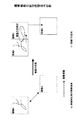
ここで、図7の例を参照しながら、実施例2における観察領域(観察試料108)の移動経路の選択手順を説明する。
まず、観察者は、例えば共焦点レーザ走査型顕微鏡本体1に備えられている接眼レンズ(不図示)を通して観察試料108の拡大像を観察する。ここで、電動XYステージ装置や電動準焦部を動作させて観察試料108上に複数の観察領域を設定してコンピュータ2へその位置を登録する。但し、この設定及び登録においては、観察領域毎に、観察(スライス像の取得)を行うZ軸方向の範囲を、例えばその範囲の境界を示すZ座標を特定する等して設定し登録する。登録された観察領域毎の位置や範囲の情報はメモリ2cに記憶される。
The system configuration according to the second embodiment can be used as it is as shown in FIG.
Here, with reference to the example of FIG. 7, a procedure for selecting the movement path of the observation region (observation sample 108) in the second embodiment will be described.
First, the observer observes an enlarged image of the
次に、実施例1に係る手法を実行して観察領域の全てについて観察順を決定する。
今、実施例1に係る手法で観察順が、図7(a)に示すように、No.1→No.2→No.3→No.4のように決定された4つの観察領域を例にして考える。このとき、各観察領域におけるZ軸方向のスライス像の取得範囲が、図7(b)に観察領域毎に「Top」及び「Bottom」と示されている境界位置で設定されているものとする。
Next, the method according to the first embodiment is executed to determine the observation order for all the observation regions.
Now, as shown in FIG. 1 → No. 2 → No. 3 → No. Consider the four observation areas determined as 4 as an example. At this time, it is assumed that the acquisition range of the slice image in the Z-axis direction in each observation region is set at the boundary positions indicated as “Top” and “Bottom” for each observation region in FIG. .
次に、決定された観察順に従い、ステージ107である電動XYステージ装置を制御し、先頭観察領域を観察位置に位置させるように観察試料108を移動させる。そして、先頭観察領域についてのスライス像の取得範囲の設定に従って電動準焦部の動作を制御し、対物レンズ106の合焦点をその範囲の一方の境界から他方の境界へと相対的に移動させながら所定の移動間隔で観察(スライス像の取得)を行う。
Next, according to the determined observation order, the electric XY stage apparatus as the
なお、この先頭観察領域において合焦点の移動を開始させるスライス像の取得範囲の境界の選択は、ここでは予め固定されているものとするが、観察者が自由に選択できるようにしてもよい。
図7の例では、まず、先頭観察領域であるNo.1の観察領域において、対物レンズ106の合焦点が「Top1」のZ軸方向位置から「Bottom1」のZ軸方向位置へと移動するように電動準焦部の動作を制御し、このとき所定の移動間隔で観察を行う。
Note that the selection of the boundary of the slice image acquisition range for starting the movement of the focal point in this head observation area is fixed in advance here, but the observer may be able to select it freely.
In the example of FIG. In one observation region, the operation of the electric focusing unit is controlled so that the focal point of the
先頭観察領域についての観察(スライス像の取得)を終えたならば、ステージ107である電動XYステージ装置を制御し、次の観察順である観察領域を観察位置に位置させるように観察試料108を移動させ、この観察領域についてのスライス像の取得範囲の設定に従って電動準焦部を制御し、対物レンズ106の合焦点をその範囲の一方の境界(「開始焦点位置」と称することとする)から他方の境界(「終了焦点位置」と称することとする)へと相対的に移動させながら所定の移動間隔で観察を行う。但し、この観察領域において合焦点の移動を開始させるスライス像の取得範囲の境界の選択は、直前の観察順の観察領域(このときは先頭観察領域)に対して行われた観察の終了時における終了焦点位置に近い方の境界を選択するものとする。
When the observation (acquisition of the slice image) for the head observation region is completed, the electric XY stage device that is the
図7の例で説明すると、先頭観察領域No.1に対する観察が対物レンズ106の合焦点が「Bottom1」のZ軸方向位置に位置したときに終了すると、ステージ107である電動XYステージ装置を制御し、観察順が二番目であるNo.2の観察領域を観察位置に位置させるように観察試料108を移動させる。ここで、図7(b)を参照すれば明らかなように、No.2の観察領域についてのスライス像の取得範囲の設定における境界「Bottom2」は、もう一方の境界「Top2」よりも終了焦点位置「Bottom1」に近い。従って、ここで電動準焦部を制御し、対物レンズ106の合焦点をまず開始焦点位置となる「Bottom2」のZ軸方向位置に位置させ、ここから終了焦点位置である「Top2」のZ軸方向位置へと対物レンズ106の合焦点を相対的に移動させながら所定の移動間隔で観察を行う。
In the example of FIG. 1 is finished when the focal point of the
以降、上述した手法と同様にして、直前の観察順の観察領域の終了焦点位置に近い方の境界を選択して次の観察順の観察領域の観察を開始する。
図7の例で引き続き説明すると、No.2の観察領域における終了焦点位置は「Top2」であり、「Top2」は次の観察順であるNo.3の観察領域におけるスライス像の取得範囲の設定における境界「Bottom3」の方が境界「Top3」よりも近いので、No.3の観察領域では開始焦点位置「Bottom3」から終了焦点位置「Top3」へ対物レンズ106の合焦点を移動させながら観察を行う。同様に、No.3に続くNo.4の観察領域では、No.3の観察領域における終了焦点位置「Top3」に近い境界「Top4」から境界「Bottom4」へ対物レンズ106の合焦点を移動させながら観察を行う。
Thereafter, in the same manner as described above, the boundary closer to the end focal position of the observation region in the previous observation order is selected, and observation of the observation region in the next observation order is started.
Continuing with the example of FIG. 2 is “Top2”, and “Top2” is the next observation order No. 2. Since the boundary “Bottom3” in the setting of the slice image acquisition range in the
以上のようにすることにより、Z軸方向における対物レンズ106の合焦点の観察試料108に対する相対的な移動経路も短くなり、電動準焦部の無駄な動作が更に少なくなるので、実験の所要時間が更に短縮され、また電動準焦部を動作させると生じる振動が観察試料108へ及ぼす影響も更に低減される。
By doing so, the relative movement path of the in-focus point of the
次に図8について説明する。同図は顕微鏡制御処理の第二の例の処理内容をフローチャートで表したときに、図6に示した第一の例と異なる部分を示したものである。この第二の例の処理は、図1に示したシステム全体を制御して多点タイムラプス観察のための実験を行わせる処理であり、上述したZ軸方向における対物レンズ106の合焦点の観察試料108に対する相対的な移動経路を短くする手法を図1に示したシステムで実現するために計算・処理部2aによって行われる処理である。なお、この処理も、前述した制御プログラム2dを計算・処理部2aで実行させると開始される。
Next, FIG. 8 will be described. This figure shows a different part from the first example shown in FIG. 6 when the processing content of the second example of the microscope control process is represented by a flowchart. The process of the second example is a process for controlling the entire system shown in FIG. 1 to perform an experiment for multi-point time-lapse observation, and the observation sample of the focal point of the
この第二の例の処理内容は、図6に示した第一の例におけるS114、S115、及びS116の各処理が図8に示されているS201からS208にかけての処理に置き換えられたものとなる。なお、この第二の例では、図8に示した処理ステップについてのみ説明することとする。 The processing content of the second example is obtained by replacing the processing of S114, S115, and S116 in the first example shown in FIG. 6 with the processing from S201 to S208 shown in FIG. . In the second example, only the processing steps shown in FIG. 8 will be described.
図6のS113の処理に続いて実行されるS201では、電動準焦部を制御して、先頭観察領域について設定されている開始焦点位置を対物レンズ106の合焦点に位置させる処理が行われる。
S202では、共焦点レーザ走査型顕微鏡本体1を制御して観察位置に現在位置している対象観察領域の画像の取得(対象観察領域処理)を行わせてメモリ2cに記憶させる処理が行われる。
In S201 executed following the process of S113 in FIG. 6, a process is performed in which the motorized focusing unit is controlled so that the start focal position set for the head observation region is located at the focal point of the
In S202, the confocal laser scanning microscope
S203では、電動準焦部の動作による観察試料108と対物レンズ106との相対的な移動によって、対物レンズ106の合焦点が、現在の対象観察領域における終了焦点位置を通り過ぎたか否かが判定され、通り過ぎた(判定結果がYes)ならば、現在の対象観察領域における今回の観察(スライス像の取得)は完了したとみなし、S205に処理を進める。一方、通り過ぎていない(S203の判定結果がNo)ならば、S204において、電動準焦部を制御して対物レンズ106の合焦点を対象観察領域の終了焦点位置の向きへ所定量だけ移動させる処理が行われ、その後はS202へと処理を戻して画像の取得処理が再度行われる。なお、この所定量は、メモリ2cに記憶されている前述した画像走査条件に基づいて設定される。
In S203, it is determined whether or not the focal point of the
S205では、S111(図6)の観察順決定処理(図5)で決定された観察順に、現在の対象観察領域に続くものが存在するか否かを判定する処理が行われ、存在する(判定結果がYes)ならばS206に処理を進め、存在しない(判定結果がNo)ならば図6のS117に処理を進め、以降図6に示した処理が行われる。 In S205, a process is performed to determine whether there is an object following the current target observation area in the observation order determined in the observation order determination process (FIG. 5) in S111 (FIG. 6). If the result is Yes), the process proceeds to S206. If it does not exist (the determination result is No), the process proceeds to S117 in FIG. 6, and the process shown in FIG. 6 is performed thereafter.
S206では、ステージ107である電動XYステージ装置を制御し、次の観察順である観察領域を対象観察領域として観察位置に位置させるように観察試料108を移動させる処理が行われる。
S207では、この対象観察領域について設定されているスライス像の取得範囲を特定する2つの境界の各々と、メモリ2cから取得される直前の観察領域の終了焦点位置との間の距離を各々算出する処理が行われ、続くS208において電動準焦部を制御して、算出された距離が短い方の境界を対物レンズ106の合焦点に位置させる処理が行われ、その後はS202へと処理を戻して画像の取得処理が再度行われる。なお、このときに対物レンズ106の合焦点に位置させた方の境界が次の観察順である観察領域における開始焦点位置となり、他方の境界がその観察領域における終了焦点位置となる。
In S206, the electric XY stage apparatus which is the
In S207, the distance between each of the two boundaries specifying the slice image acquisition range set for the target observation area and the end focal position of the observation area immediately before acquired from the
以上の顕微鏡制御処理の第二の例を計算・処理部2aが実行することによって、図1に示したシステムで、Z軸方向における対物レンズ106の合焦点の観察試料108に対する相対的な移動経路の短い、多点タイムラプス観察のための実験が可能となる。
次に本発明の更なる別の実施例である実施例3について説明する。
When the calculation /
Next,
例えば多点タイムラプス観察における生細胞の時系列観察において、細胞の形状に変化が生じたり細胞が移動したりした場合に、その実験中に観察領域を追加設定する必要性が生じることがある。
例えば、図9(a)に示すように、観察領域の観察順が前述した観察順決定処理(図5)によって「領域A」→「領域B」と決定されていたときに、領域Aに含まれていた細胞が実験開始後に成長したために領域Aのみでは全体像を観察しきれなくなってしまった場合を考える。このときには、図9(b)に示すように、領域Aに隣接する領域Cを実験開始後に追加しなければ全体像が観察できない。
For example, in the time-series observation of living cells in multipoint time-lapse observation, when the cell shape changes or the cells move, it may be necessary to additionally set an observation area during the experiment.
For example, as shown in FIG. 9A, when the observation order of the observation area is determined as “area A” → “area B” by the above-described observation order determination process (FIG. 5), it is included in the area A. Consider a case in which the whole image cannot be observed with only the region A because the grown cells have grown after the start of the experiment. At this time, as shown in FIG. 9B, the entire image cannot be observed unless the region C adjacent to the region A is added after the start of the experiment.
実施例3では、このような実験開始後の観察領域の追加設定を可能とする。
実施例3に係るシステム構成は、図1に示したものをそのまま使用することができる。
次に図10について説明する。同図は顕微鏡制御処理の第三の例の処理内容をフローチャートで表したときに、図6に示した第一の例と異なる部分を示したものである。この第三の例の処理は、図1に示したシステム全体を制御して多点タイムラプス観察のための実験を行わせる処理であり、上述した実験開始後の観察領域の追加を図1に示したシステムで可能とするために計算・処理部2aによって行われる処理である。なお、この処理も、前述した制御プログラム2dを計算・処理部2aで実行させると開始される。
In Example 3, such additional setting of the observation area after the start of the experiment is possible.
The system configuration according to the third embodiment can be used as it is as shown in FIG.
Next, FIG. 10 will be described. This figure shows a different part from the first example shown in FIG. 6 when the processing content of the third example of the microscope control process is represented by a flowchart. The process of the third example is a process for controlling the entire system shown in FIG. 1 to perform an experiment for multipoint time-lapse observation. The addition of the observation area after the start of the experiment is shown in FIG. This processing is performed by the calculation /
この第二の例の処理内容は、図6に示した第一の例におけるS118の処理が図10に示されているS301からS304にかけての処理に置き換えられたものとなる。なお、この第三の例では、図10に示した処理ステップについてのみ説明することとする。
図6のS117の判定結果がNoであったときに実行されるS301では、前述したタイマが予め設定されていた所定時間の経過を計時したか否かを判定する処理が行われ、所定時間の経過が計時されたならば(判定結果がYesとなったならば)図6のS119に処理を進める。一方、所定時間の経過を未だ計時していないならば(判定結果がNoならば)S302に処理を進める。
The processing content of the second example is obtained by replacing the processing of S118 in the first example shown in FIG. 6 with the processing from S301 to S304 shown in FIG. In the third example, only the processing steps shown in FIG. 10 will be described.
In S301, which is executed when the determination result of S117 in FIG. 6 is No, a process for determining whether or not the above-described timer has elapsed for a predetermined time is performed. If the time has elapsed (if the determination result is Yes), the process proceeds to S119 in FIG. On the other hand, if the predetermined time has not yet been counted (if the determination result is No), the process proceeds to S302.
S302では、観察領域の追加の指示を取得したか否かを判定する処理が行われる。なお、この観察領域の追加は、例えばユーザが操作パネル3を操作して観察領域の位置等の情報を入力することによりなされるが、その代わりに、例えば一定の時間間隔で取得されている観察領域の画像に表されている細胞等の同一試料の像の輪郭の一部にある時刻において突然欠けが生じたことを検出し、この検出結果に基づいて追加すべき観察領域の位置等の情報を計算・処理部2a自身が生成して追加するようにしてもよい。
In S302, processing for determining whether or not an instruction to add an observation area has been acquired is performed. The addition of the observation area is performed, for example, when the user operates the
このS302の判定処理において、この指示を取得したのであれば(判定結果がYesならば)、S303において、この指示に係る追加の観察領域についての情報をメモリ2cに記憶させる処理が行われ、続くS304において、図5に示した観察順決定処理が、追加されたものを含む全ての観察領域を対象として行われ、その後はS301へ処理を戻して上述した処理が繰り返される。
If this instruction has been acquired in the determination process of S302 (if the determination result is Yes), in S303, a process for storing information about the additional observation area according to this instruction in the
一方、S302の判定処理において、観察領域の追加の指示を取得していないならば(判定結果がNoならば)、直ちにS301へ処理を戻して上述した処理が繰り返される。
以上の顕微鏡制御処理の第三の例を計算・処理部2aが実行することによって、図1に示したシステムで、実験開始後の観察領域を追加することのできる、多点タイムラプス観察のための実験が可能となる。
On the other hand, in the determination process of S302, if an instruction to add an observation area has not been acquired (if the determination result is No), the process immediately returns to S301 and the above-described process is repeated.
When the calculation /
なお、図8に示した変更を図6に示したフローチャートへ加えた顕微鏡処理の第二の例に対し、図10に示した変更を更に加えることにより、実施例2においても多点タイムラプス観察のための実験の開始後に観察領域を追加することができるようになる。
なお、図5、図6、図8、及び図10の各々にフローチャートで示した処理をコンピュータ2の計算・処理部2aが有しているCPU(不図示)に行わせるための制御プログラム2dをコンピュータ読み取り可能な記録媒体に記録させておき、そのプログラムを記録媒体からコンピュータ2に読み込ませてCPUで実行させるようにしても、図1に示したシステムで前述した多点タイムラプス観察の実験を行うための制御をコンピュータ2に行わせることができる。
8 is added to the second example of the microscopic processing in which the change shown in FIG. 8 is added to the flowchart shown in FIG. 6, the multi-point time lapse observation is also performed in Example 2 by further adding the change shown in FIG. 10. The observation area can be added after the start of the experiment.
Note that a control program 2d for causing a CPU (not shown) included in the calculation /
記録させた制御プログラムをコンピュータで読み取ることの可能な記録媒体としては、図11に示すように、例えば、コンピュータ200に内蔵若しくは外付けの付属装置として備えられるROMやハードディスク装置などの記憶装置201、フレキシブルディスク、MO(光磁気ディスク)、CD−ROM、DVD−ROMなどといった、コンピュータ200に設けられている媒体駆動装置202によって読み取り可能な携帯可能記録媒体403等が利用できる。
As a recording medium from which the recorded control program can be read by a computer, as shown in FIG. 11, for example, a
また、このような記録媒体はネットワーク回線204を介してコンピュータ200と接続される、プログラムサーバ205として機能するコンピュータが備えている記憶装置206であってもよい。この場合には、制御プログラムを表現するデータ信号で搬送波を変調して得られる伝送信号を、プログラムサーバ205から伝送媒体であるネットワーク回線204を通じてコンピュータ200へ伝送するようにし、コンピュータ200では受信した伝送信号を復調して制御プログラムを再生することでこの制御プログラムをコンピュータ200内のCPUで実行できるようになる。
Such a recording medium may be a
その他、本発明は、上述した実施形態に限定されることなく、本発明の要旨を逸脱しない範囲内で種々の改良・変更が可能である。
例えば、上述した各実施形態においては、多点タイムラプス観察のため対物レンズ106の合焦点の観察領域の画像の取得を行うようにしていた(図6のS114や図8のS202)が、この画像の取得の処理に代えて、若しくは画像の取得の処理に併せて、対物レンズ106を介して強いレーザ光を観察試料108の対象観察領域へ照射する処理を行うようにして、対物レンズ106の合焦点に順次位置する対象観察領域に含まれる細胞等へ次々と刺激を与えるといった対象観察領域への処理を行うようにしてもよい。
In addition, the present invention is not limited to the above-described embodiments, and various improvements and changes can be made without departing from the scope of the present invention.
For example, in each of the above-described embodiments, an image of the observation region at the focal point of the
1 共焦点レーザ顕微鏡本体
2 コンピュータ
2a 計算・処理部
2b A/D変換器
2c メモリ
2d 制御プログラム
3 操作パネル
4 レーザ装置
5 画像モニタ
101 光電変換器
102 励起用ダイクロイックミラー
103 ダイクロイックミラー
104 走査ユニット
105 レボルバ
106 対物レンズ
107 ステージ
108 観察試料
109 レンズ
110 コンフォーカルアパーチャ
111 バリアフィルタ
200 コンピュータ
201 記憶装置
202 媒体駆動装置
203 携帯可能記録媒体
204 ネットワーク回線
205 プログラムサーバ
206 記憶装置
DESCRIPTION OF
Claims (10)
前記観察試料に対してなされる複数の観察領域の各々の前記平面上における位置の設定を取得する観察領域位置設定取得手段と、
前記対物レンズの合焦位置が位置している前記観察領域である対象観察領域の画像の取得の処理、若しくは当該対象観察領域への刺激の処理を行う対象観察領域処理手段と、
前記対象観察領域と他の前記観察領域との間の距離を算出する算出手段と、
前記平面移動手段を制御して前記観察試料を移動させて、前記観察領域のうち前記画像の取得の処理若しくは前記刺激の処理が未だ行われていないものであって且つ前記対象観察領域との間の前記距離が最短であるものを、前記対物レンズの合焦位置に位置させる平面移動制御手段と、
を有することを特徴とする顕微鏡装置。 A plane moving means for moving the observation sample on a plane perpendicular to the optical axis of the objective lens;
An observation region position setting acquisition means for acquiring a setting of a position on each plane of a plurality of observation regions made with respect to the observation sample;
Target observation area processing means for performing processing for acquiring an image of the target observation area, which is the observation area where the in-focus position of the objective lens is located, or processing for stimulating the target observation area;
Calculating means for calculating a distance between the target observation area and the other observation area;
The plane moving means is controlled to move the observation sample, and the image acquisition process or the stimulation process is not yet performed in the observation area and between the observation area and the target observation area. A plane movement control means for positioning the one having the shortest distance at a focus position of the objective lens;
A microscope apparatus characterized by comprising:
前記平面移動手段を制御して前記観察試料を移動させ、前記先頭観察領域を前記対物レンズの合焦位置へ位置させる初動制御手段と、
いずれかの前記観察領域が前記対物レンズの合焦位置に位置したときに前記画像の取得の処理若しくは前記刺激の処理を前記対象観察領域処理手段に行わせる対象観察領域処理制御手段と、
を更に有し、
前記平面移動制御手段は、前記対象観察領域処理手段による前記画像の取得の処理若しくは前記刺激の処理がひとつの前記対象観察領域に対して完了してから前記平面移動手段を制御する、
ことを特徴とする請求項1に記載の顕微鏡装置。 Selection acquisition means for acquiring a setting of selection of the first observation area that is the first target observation area selected from the observation area;
Initial movement control means for controlling the plane moving means to move the observation sample, and to position the head observation area to a focus position of the objective lens;
A target observation region processing control unit that causes the target observation region processing unit to perform the image acquisition process or the stimulus processing when any one of the observation regions is located at a focus position of the objective lens;
Further comprising
The plane movement control means controls the plane movement means after the image acquisition process or the stimulation process by the target observation area processing means is completed for one target observation area.
The microscope apparatus according to claim 1.
前記初動制御手段は、前記所定の時間が経過する度に前記平面移動手段の制御を改めて開始し、
前記平面移動制御手段は、前記所定の時間が経過する度に全ての前記観察領域について前記画像の取得の処理若しくは前記刺激の処理が行われていないものとして前記平面移動手段の制御を行う、
ことを特徴とする請求項2に記載の顕微鏡装置。 It further has a timing means for timing the passage of a predetermined time,
The initial motion control means starts again the control of the plane moving means every time the predetermined time elapses,
The plane movement control means controls the plane movement means on the assumption that the image acquisition process or the stimulation process is not performed for all the observation regions every time the predetermined time elapses.
The microscope apparatus according to claim 2.
前記観察領域の各々における前記光軸方向の位置の範囲の設定を取得する観察領域範囲取得手段と、
前記観察領域が前記対物レンズの合焦位置に位置したときに前記光軸方向移動手段を制御して前記位置関係を変化させて、前記観察試料に対する前記対物レンズの焦点の位置を、前記対象観察領域について設定されている前記範囲を特定している一方の境界から他方の境界まで一定の向きに変化させる光軸方向移動制御手段と、
を更に有し、
前記対象観察領域処理手段は、前記対象観察領域での前記観察試料に対する前記対物レンズの焦点の位置の変化量が所定の量に達する毎に、当該対象観察領域に対する前記画像の取得の処理若しくは前記刺激の処理を行う、
ことを特徴とする請求項1に記載の顕微鏡装置。 An optical axis direction moving means for changing a relative positional relationship between the focal point of the objective lens and the observation sample in the optical axis direction of the objective lens;
An observation region range acquisition means for acquiring a setting of a range of a position in the optical axis direction in each of the observation regions;
When the observation region is located at the in-focus position of the objective lens, the optical axis direction moving means is controlled to change the positional relationship, and the position of the focus of the objective lens with respect to the observation sample is changed to the target observation. An optical axis direction movement control means for changing in a certain direction from one boundary to the other boundary specifying the range set for a region;
Further comprising
The target observation region processing means is configured to acquire the image for the target observation region each time the amount of change in the focal position of the objective lens with respect to the observation sample in the target observation region reaches a predetermined amount, or Do stimulus processing,
The microscope apparatus according to claim 1.
前記光軸方向移動制御手段は、前記対象観察領域について設定されている前記範囲を特定している2つの境界のうち、前記終了時焦点位置取得手段によって直近に取得されていた前記終了焦点位置と近い方の境界から遠い方の境界へと前記観察試料に対する前記対物レンズの焦点の位置を変化させる、
ことを特徴とする請求項4に記載の顕微鏡装置。 An end focal position acquisition unit that acquires an end focal position that is a focal point position of the objective lens with respect to the observation sample when the control by the optical axis direction movement control unit is completed;
The optical axis direction movement control means includes the end focus position acquired most recently by the end focus position acquisition means among the two boundaries that specify the range set for the target observation area. Changing the position of the focal point of the objective lens relative to the observation sample from a near boundary to a far boundary;
The microscope apparatus according to claim 4.
前記観察試料に対してなされる複数の観察領域の各々の前記平面上における位置の設定を取得する観察領域位置設定取得手段と、
前記対物レンズの合焦位置が位置している前記観察領域である対象観察領域の画像の取得の処理、若しくは当該対象観察領域への刺激の処理を行う対象観察領域処理手段と、
前記対象観察領域と他の前記観察領域との間の距離を算出する算出手段と、
前記観察領域の全てを前記対物レンズの合焦位置に順次位置させるべく前記観察試料の移動をさせるときに、前記距離に基づく順序であって当該移動の経路長を短くする当該順序で当該観察試料を移動させるように前記平面移動手段を制御する平面移動制御手段と、
を有することを特徴とする顕微鏡装置。 A plane moving means for moving the observation sample on a plane perpendicular to the optical axis of the objective lens;
An observation region position setting acquisition means for acquiring a setting of a position on each plane of a plurality of observation regions made with respect to the observation sample;
Target observation area processing means for performing processing for acquiring an image of the target observation area, which is the observation area where the in-focus position of the objective lens is located, or processing for stimulating the target observation area;
Calculating means for calculating a distance between the target observation area and the other observation area;
When the observation sample is moved so that all of the observation region is sequentially positioned at the in-focus position of the objective lens, the observation sample is in the order based on the distance and the movement path length is shortened. Plane movement control means for controlling the plane movement means so as to move
A microscope apparatus characterized by comprising:
前記対物レンズの光軸に対して垂直な平面上で前記観察試料を移動させて、前記観察領域のうち当該観察領域の画像の取得の処理若しくは当該観察領域への刺激の処理が前記顕微鏡装置によって未だ行われていないものであって且つ前記対象観察領域との間の前記距離が最短であるものを、当該対物レンズの合焦位置に位置させる、
ことを特徴とする顕微鏡装置の制御方法。 Among the observation regions that are set for the observation sample that is the observation target in the microscope device, the target observation region that is the observation region where the in-focus position of the objective lens provided in the microscope device is located, and other observation regions Calculate the distance to the observation area,
By moving the observation sample on a plane perpendicular to the optical axis of the objective lens, the microscope apparatus performs processing for acquiring an image of the observation region in the observation region or processing for stimulating the observation region. The one that has not yet been performed and that has the shortest distance to the target observation area is positioned at the in-focus position of the objective lens,
A method for controlling a microscope apparatus, comprising:
前記対物レンズの光軸に対して垂直な平面上で前記観察試料を移動させて、前記観察領域のうち当該観察領域の画像の取得の処理若しくは当該観察領域への刺激の処理が前記顕微鏡装置によって未だ行われていないものであって且つ前記対象観察領域との間の前記距離が最短であるものを、当該対物レンズの合焦位置に位置させる処理と、
をコンピュータに行わせるためのプログラム。
Among the observation regions that are set for the observation sample that is the observation target in the microscope device, the target observation region that is the observation region where the in-focus position of the objective lens provided in the microscope device is located, and other observation regions A process of calculating a distance between the observation area,
By moving the observation sample on a plane perpendicular to the optical axis of the objective lens, the microscope apparatus performs processing for acquiring an image of the observation region in the observation region or processing for stimulating the observation region. A process that has not yet been performed and that has the shortest distance to the target observation area, is positioned at the in-focus position of the objective lens; and
A program that causes a computer to perform
Priority Applications (2)
| Application Number | Priority Date | Filing Date | Title |
|---|---|---|---|
| JP2004007521A JP4664599B2 (en) | 2004-01-15 | 2004-01-15 | Microscope equipment |
| US11/024,380 US7238934B2 (en) | 2004-01-15 | 2004-12-28 | Microscope apparatus and method for controlling microscope apparatus |
Applications Claiming Priority (1)
| Application Number | Priority Date | Filing Date | Title |
|---|---|---|---|
| JP2004007521A JP4664599B2 (en) | 2004-01-15 | 2004-01-15 | Microscope equipment |
Publications (3)
| Publication Number | Publication Date |
|---|---|
| JP2005202087A true JP2005202087A (en) | 2005-07-28 |
| JP2005202087A5 JP2005202087A5 (en) | 2007-03-01 |
| JP4664599B2 JP4664599B2 (en) | 2011-04-06 |
Family
ID=34747149
Family Applications (1)
| Application Number | Title | Priority Date | Filing Date |
|---|---|---|---|
| JP2004007521A Expired - Fee Related JP4664599B2 (en) | 2004-01-15 | 2004-01-15 | Microscope equipment |
Country Status (2)
| Country | Link |
|---|---|
| US (1) | US7238934B2 (en) |
| JP (1) | JP4664599B2 (en) |
Cited By (7)
| Publication number | Priority date | Publication date | Assignee | Title |
|---|---|---|---|---|
| JP2008058249A (en) * | 2006-09-01 | 2008-03-13 | Olympus Corp | Apparatus and method for viewing photometry |
| JP2008185922A (en) * | 2007-01-31 | 2008-08-14 | Nikon Corp | Microscope |
| US7982170B2 (en) | 2008-09-29 | 2011-07-19 | Olympus Corporation | Microscope system |
| JP2012002949A (en) * | 2010-06-15 | 2012-01-05 | Nikon Corp | Observation device |
| EP2503373A1 (en) | 2011-03-23 | 2012-09-26 | Olympus Corporation | Microscope performing 3D imaging |
| JP2013050667A (en) * | 2011-08-31 | 2013-03-14 | Nikon Corp | Microscope controller, image processor, microscope device, and program |
| JP2019074669A (en) * | 2017-10-17 | 2019-05-16 | 株式会社キーエンス | Magnifying observation apparatus |
Families Citing this family (6)
| Publication number | Priority date | Publication date | Assignee | Title |
|---|---|---|---|---|
| JP5132052B2 (en) * | 2005-11-30 | 2013-01-30 | オリンパス株式会社 | Scanning laser microscope condition setting device and scanning laser microscope system |
| JP4893275B2 (en) * | 2006-11-30 | 2012-03-07 | 株式会社ニコン | Microscope equipment |
| WO2008155883A1 (en) * | 2007-06-15 | 2008-12-24 | Nikon Corporation | Confocal microscope device |
| JP2011095685A (en) * | 2009-11-02 | 2011-05-12 | Sony Corp | Microscope system and method for controlling the microscope system |
| JP5784790B2 (en) * | 2014-04-28 | 2015-09-24 | オリンパス株式会社 | Fluorescence observation equipment |
| CN104914564A (en) * | 2015-06-24 | 2015-09-16 | 中山安荞生物科技有限公司 | Microscope |
Citations (7)
| Publication number | Priority date | Publication date | Assignee | Title |
|---|---|---|---|---|
| JPS6111714A (en) * | 1984-06-26 | 1986-01-20 | Matsushita Electric Ind Co Ltd | Automatic focus adjuster of microscope |
| JP2000056235A (en) * | 1998-08-12 | 2000-02-25 | Olympus Optical Co Ltd | Inspection microscope system |
| JP2000295462A (en) * | 1999-02-04 | 2000-10-20 | Olympus Optical Co Ltd | Transmission system for microscope image |
| JP2002277754A (en) * | 2001-03-22 | 2002-09-25 | Olympus Optical Co Ltd | Photomicrographing device |
| JP2003015056A (en) * | 2001-06-29 | 2003-01-15 | Matsushita Electric Ind Co Ltd | Method and device for picking up image |
| JP2003307681A (en) * | 2002-04-17 | 2003-10-31 | Olympus Optical Co Ltd | Confocal scanning optical microscope |
| JP2004004678A (en) * | 2002-03-27 | 2004-01-08 | Olympus Corp | Confocal microscope apparatus and observation method using confocal microscope apparatus |
Family Cites Families (2)
| Publication number | Priority date | Publication date | Assignee | Title |
|---|---|---|---|---|
| JPH0627383A (en) | 1992-07-08 | 1994-02-04 | Olympus Optical Co Ltd | Method and device for picture display |
| SE517626C3 (en) * | 2001-04-12 | 2002-09-04 | Cellavision Ab | Microscopy procedure for scanning and positioning an object, where images are taken and joined in the same image coordinate system to accurately set the microscope table |
-
2004
- 2004-01-15 JP JP2004007521A patent/JP4664599B2/en not_active Expired - Fee Related
- 2004-12-28 US US11/024,380 patent/US7238934B2/en active Active
Patent Citations (7)
| Publication number | Priority date | Publication date | Assignee | Title |
|---|---|---|---|---|
| JPS6111714A (en) * | 1984-06-26 | 1986-01-20 | Matsushita Electric Ind Co Ltd | Automatic focus adjuster of microscope |
| JP2000056235A (en) * | 1998-08-12 | 2000-02-25 | Olympus Optical Co Ltd | Inspection microscope system |
| JP2000295462A (en) * | 1999-02-04 | 2000-10-20 | Olympus Optical Co Ltd | Transmission system for microscope image |
| JP2002277754A (en) * | 2001-03-22 | 2002-09-25 | Olympus Optical Co Ltd | Photomicrographing device |
| JP2003015056A (en) * | 2001-06-29 | 2003-01-15 | Matsushita Electric Ind Co Ltd | Method and device for picking up image |
| JP2004004678A (en) * | 2002-03-27 | 2004-01-08 | Olympus Corp | Confocal microscope apparatus and observation method using confocal microscope apparatus |
| JP2003307681A (en) * | 2002-04-17 | 2003-10-31 | Olympus Optical Co Ltd | Confocal scanning optical microscope |
Cited By (10)
| Publication number | Priority date | Publication date | Assignee | Title |
|---|---|---|---|---|
| JP2008058249A (en) * | 2006-09-01 | 2008-03-13 | Olympus Corp | Apparatus and method for viewing photometry |
| JP2008185922A (en) * | 2007-01-31 | 2008-08-14 | Nikon Corp | Microscope |
| US7982170B2 (en) | 2008-09-29 | 2011-07-19 | Olympus Corporation | Microscope system |
| JP2012002949A (en) * | 2010-06-15 | 2012-01-05 | Nikon Corp | Observation device |
| EP2503373A1 (en) | 2011-03-23 | 2012-09-26 | Olympus Corporation | Microscope performing 3D imaging |
| JP2012203048A (en) * | 2011-03-23 | 2012-10-22 | Olympus Corp | Microscope |
| US8958146B2 (en) | 2011-03-23 | 2015-02-17 | Olympus Corporation | 3D imaging microscope |
| JP2013050667A (en) * | 2011-08-31 | 2013-03-14 | Nikon Corp | Microscope controller, image processor, microscope device, and program |
| JP2019074669A (en) * | 2017-10-17 | 2019-05-16 | 株式会社キーエンス | Magnifying observation apparatus |
| JP7023667B2 (en) | 2017-10-17 | 2022-02-22 | 株式会社キーエンス | Magnifying observation device |
Also Published As
| Publication number | Publication date |
|---|---|
| JP4664599B2 (en) | 2011-04-06 |
| US20050156106A1 (en) | 2005-07-21 |
| US7238934B2 (en) | 2007-07-03 |
Similar Documents
| Publication | Publication Date | Title |
|---|---|---|
| JP4664599B2 (en) | Microscope equipment | |
| JP5814709B2 (en) | Time-lapse observation method and time-lapse observation apparatus used therefor | |
| US20050280818A1 (en) | Confocal observation system | |
| JP5873721B2 (en) | Method and device for signal acquisition in laser scanning microscopy | |
| JP4700299B2 (en) | Confocal scanning microscope | |
| JP2005121796A (en) | Laser microscope | |
| JP7064796B2 (en) | Image reconstruction method, device and microimaging device | |
| CN109276229B (en) | Rapid focusing system and method for photoacoustic microscopic imaging | |
| JP2010085420A (en) | Microscope system | |
| JP2012155010A (en) | Microscope system, surface state observation method, and surface state observation program | |
| JP2006293219A (en) | Scanning type confocal microscope and method of measuring sample information | |
| JP6832093B2 (en) | Microscope system | |
| TWI554740B (en) | Optical system for fast three-dimensional imaging | |
| JP7030986B2 (en) | Image generator, image generator and image generator | |
| JP5299078B2 (en) | Laser scanning microscope, three-dimensional image acquisition method, and program | |
| JP2012212133A (en) | Laser microscope and observation method | |
| JP4803974B2 (en) | Confocal observation system, light irradiation method, and light irradiation program | |
| JP2006308338A (en) | Ultrasonic image inspection method, ultrasonic imaging inspection device, and ultrasonic pseudo-staining method | |
| JP2007183425A (en) | Observation device | |
| US10168523B2 (en) | Image generating system, image generating method, and image generating apparatus | |
| JP2006084960A (en) | Three-dimensional confocal microscopic system | |
| JP2007309776A (en) | Microscope apparatus and cell observation method | |
| JP2005115072A (en) | Scanning laser microscope, its control method and program | |
| JP7015144B2 (en) | Image processing equipment and microscope system | |
| JP2005345764A (en) | Scanning optical device |
Legal Events
| Date | Code | Title | Description |
|---|---|---|---|
| A521 | Written amendment |
Free format text: JAPANESE INTERMEDIATE CODE: A523 Effective date: 20070110 |
|
| A621 | Written request for application examination |
Free format text: JAPANESE INTERMEDIATE CODE: A621 Effective date: 20070110 |
|
| A977 | Report on retrieval |
Free format text: JAPANESE INTERMEDIATE CODE: A971007 Effective date: 20100203 |
|
| A131 | Notification of reasons for refusal |
Free format text: JAPANESE INTERMEDIATE CODE: A131 Effective date: 20100302 |
|
| A521 | Written amendment |
Free format text: JAPANESE INTERMEDIATE CODE: A523 Effective date: 20100427 |
|
| A02 | Decision of refusal |
Free format text: JAPANESE INTERMEDIATE CODE: A02 Effective date: 20100824 |
|
| A521 | Written amendment |
Free format text: JAPANESE INTERMEDIATE CODE: A523 Effective date: 20101119 |
|
| A911 | Transfer to examiner for re-examination before appeal (zenchi) |
Free format text: JAPANESE INTERMEDIATE CODE: A911 Effective date: 20101129 |
|
| TRDD | Decision of grant or rejection written | ||
| A01 | Written decision to grant a patent or to grant a registration (utility model) |
Free format text: JAPANESE INTERMEDIATE CODE: A01 Effective date: 20101221 |
|
| A01 | Written decision to grant a patent or to grant a registration (utility model) |
Free format text: JAPANESE INTERMEDIATE CODE: A01 |
|
| A61 | First payment of annual fees (during grant procedure) |
Free format text: JAPANESE INTERMEDIATE CODE: A61 Effective date: 20110107 |
|
| R151 | Written notification of patent or utility model registration |
Ref document number: 4664599 Country of ref document: JP Free format text: JAPANESE INTERMEDIATE CODE: R151 |
|
| FPAY | Renewal fee payment (event date is renewal date of database) |
Free format text: PAYMENT UNTIL: 20140114 Year of fee payment: 3 |
|
| S531 | Written request for registration of change of domicile |
Free format text: JAPANESE INTERMEDIATE CODE: R313531 |
|
| R350 | Written notification of registration of transfer |
Free format text: JAPANESE INTERMEDIATE CODE: R350 |
|
| R250 | Receipt of annual fees |
Free format text: JAPANESE INTERMEDIATE CODE: R250 |
|
| LAPS | Cancellation because of no payment of annual fees |