JP2005201174A - Failure diagnostic device - Google Patents
Failure diagnostic device Download PDFInfo
- Publication number
- JP2005201174A JP2005201174A JP2004009414A JP2004009414A JP2005201174A JP 2005201174 A JP2005201174 A JP 2005201174A JP 2004009414 A JP2004009414 A JP 2004009414A JP 2004009414 A JP2004009414 A JP 2004009414A JP 2005201174 A JP2005201174 A JP 2005201174A
- Authority
- JP
- Japan
- Prior art keywords
- angle sensor
- pressure
- crank angle
- detected
- failure
- Prior art date
- Legal status (The legal status is an assumption and is not a legal conclusion. Google has not performed a legal analysis and makes no representation as to the accuracy of the status listed.)
- Withdrawn
Links
Images


Classifications
-
- F—MECHANICAL ENGINEERING; LIGHTING; HEATING; WEAPONS; BLASTING
- F02—COMBUSTION ENGINES; HOT-GAS OR COMBUSTION-PRODUCT ENGINE PLANTS
- F02D—CONTROLLING COMBUSTION ENGINES
- F02D41/00—Electrical control of supply of combustible mixture or its constituents
- F02D41/009—Electrical control of supply of combustible mixture or its constituents using means for generating position or synchronisation signals
-
- F—MECHANICAL ENGINEERING; LIGHTING; HEATING; WEAPONS; BLASTING
- F02—COMBUSTION ENGINES; HOT-GAS OR COMBUSTION-PRODUCT ENGINE PLANTS
- F02D—CONTROLLING COMBUSTION ENGINES
- F02D41/00—Electrical control of supply of combustible mixture or its constituents
- F02D41/22—Safety or indicating devices for abnormal conditions
- F02D41/222—Safety or indicating devices for abnormal conditions relating to the failure of sensors or parameter detection devices
-
- F—MECHANICAL ENGINEERING; LIGHTING; HEATING; WEAPONS; BLASTING
- F02—COMBUSTION ENGINES; HOT-GAS OR COMBUSTION-PRODUCT ENGINE PLANTS
- F02D—CONTROLLING COMBUSTION ENGINES
- F02D35/00—Controlling engines, dependent on conditions exterior or interior to engines, not otherwise provided for
- F02D35/02—Controlling engines, dependent on conditions exterior or interior to engines, not otherwise provided for on interior conditions
- F02D35/023—Controlling engines, dependent on conditions exterior or interior to engines, not otherwise provided for on interior conditions by determining the cylinder pressure
Abstract
Description
本発明は、エンジンに設けられる軸の状態を検知する検知装置の故障診断装置に関し、特に、エンジンの燃焼室内の圧力に基づいて検知装置の故障を診断する故障診断装置に関する。 The present invention relates to a failure diagnosis device for a detection device that detects a state of a shaft provided in an engine, and more particularly, to a failure diagnosis device that diagnoses a failure of a detection device based on a pressure in a combustion chamber of an engine.
従来、エンジンの燃焼室における燃焼により発生する駆動力により回転する軸の状態を検知する検知装置がエンジンに設けられる。たとえば、クランク角センサは、クランクシャフトの回転角の状態を検知する。このクランク角センサが故障すると、エンジンの回転数が不明となり、エンジンの回転数に基づく制御を行なうことが困難となる。 2. Description of the Related Art Conventionally, a detection device that detects a state of a rotating shaft by a driving force generated by combustion in a combustion chamber of an engine is provided in the engine. For example, the crank angle sensor detects the state of the rotation angle of the crankshaft. If this crank angle sensor fails, the engine speed becomes unknown, and it becomes difficult to perform control based on the engine speed.
そこで、上述の問題に鑑み、特開昭58−197452号公報(特許文献1)は、クランク角センサが故障した場合でも支障なく点火動作および燃料噴射を行なうことのできる電子制御装置を開示する。この電子制御装置は、クランク角センサの信号が出力されなくなった場合にクランク角センサが故障したものと判定し、その場合には、クランク角センサの信号以外の運転状態信号(たとえば、吸気量信号)から期間の回転速度を検出し、その値に対応した周波数の信号を点火信号および噴射パルスの代わりとするように自動的に切り換えるように構成している。 In view of the above problems, Japanese Patent Application Laid-Open No. 58-197452 (Patent Document 1) discloses an electronic control device that can perform an ignition operation and fuel injection without any trouble even when a crank angle sensor fails. The electronic control unit determines that the crank angle sensor has failed when the crank angle sensor signal is not output. In this case, the electronic control device determines an operation state signal other than the crank angle sensor signal (for example, an intake air amount signal). ) To detect the rotational speed of the period, and automatically switch so that the signal of the frequency corresponding to the value is used in place of the ignition signal and the injection pulse.
特許文献1によると、クランク角センサが故障した場合でも、広い運転範囲にわたって安定した運転を行なうことが可能となる。
特許文献1において、クランク角センサの故障は、クランク角センサの信号が出力されなかった場合に判定される。また、特許文献1は、クランク角センサの信号の代わりに吸気量信号から回転速度を検出する方法を開示する。 In Patent Document 1, the failure of the crank angle sensor is determined when the crank angle sensor signal is not output. Patent Document 1 discloses a method for detecting a rotational speed from an intake air amount signal instead of a crank angle sensor signal.
しかしながら、クランク角センサの出力信号の有無による故障の判定および吸気量に基づいてクランクシャフトの回転速度の検知を行なう特許文献1における電子制御装置では、気筒判別およびクランクシャフトの回転角が不明のため、パルス抜け、ノイズなどによるパルス多発などのクランク角センサの異常を検出することができない。また、吸気量に基づいてクランク角センサの異常を判定すると、吸気量が少ないときは、クランク角センサの異常が判定できない。 However, in the electronic control device disclosed in Patent Document 1 that performs failure determination based on the presence or absence of the output signal of the crank angle sensor and detection of the rotation speed of the crankshaft based on the intake air amount, the cylinder discrimination and the rotation angle of the crankshaft are unknown. It is impossible to detect abnormalities in the crank angle sensor such as pulse missing due to missing pulses or noise. Further, when the abnormality of the crank angle sensor is determined based on the intake air amount, the abnormality of the crank angle sensor cannot be determined when the intake air amount is small.
本発明は、上述した課題を解決するためになされたものであって、その目的は、クランク角センサの異常を、正確に検出する故障診断装置を提供することである。 The present invention has been made to solve the above-described problems, and an object of the present invention is to provide a failure diagnosis apparatus that accurately detects an abnormality of a crank angle sensor.
第1の発明に係る故障診断装置は、エンジンに設けられ、エンジンの燃焼室における燃焼により発生する駆動力により回転する軸の状態を検知する検知装置の故障を診断する故障診断装置である。故障診断装置は、燃焼室内の圧力を検知するための圧力検知手段と、圧力検知手段により検知される圧力の変化に基づき解析される軸の状態と、検知装置により検知される軸の状態とに基づいて、軸の回転に伴い変化する物理量の異常を検知して、検知装置の故障を診断するための診断手段とを含む。 A failure diagnosis apparatus according to a first aspect of the present invention is a failure diagnosis apparatus that diagnoses a failure of a detection device that is provided in an engine and detects a state of a shaft that rotates by a driving force generated by combustion in a combustion chamber of the engine. The failure diagnosis device includes a pressure detection means for detecting the pressure in the combustion chamber, a shaft state analyzed based on a change in pressure detected by the pressure detection means, and a shaft state detected by the detection device. And diagnostic means for diagnosing a failure of the detection device by detecting an abnormality in the physical quantity that changes with rotation of the shaft.
第1の発明によると、故障診断装置は、エンジンに設けられ、エンジンの燃焼室における燃焼により発生する駆動力により回転する軸(たとえば、クランクシャフト)の状態(たとえば、回転角の状態)を検知する検知装置(たとえば、クランク角センサ)の故障を診断する。そして、故障診断装置は、燃焼室内の圧力を検知するための圧力検知手段と、圧力検知手段により検知される圧力の変化に基づき解析される回転角と、クランク角センサにより検知される回転角とに基づいて、クランクシャフトの回転に伴い変化する物理量の異常を検知して、クランク角センサの故障を診断する。これにより、たとえば、圧力検知手段により検知される圧力が予め定められた値以上となるときに、クランク角センサから予め定められた入力があるか否かを検知する。このとき、予め定められた入力がないとクランク角センサが故障したと診断する。具体的には、たとえば、複数の気筒を有するエンジンにおいて、気筒内の燃焼による圧力の変化は、クランクシャフトの回転角と対応づけることができる。すなわち、予め定められた気筒において、圧力検知手段により検知される圧力が極大値となる時(たとえば、燃焼圧のピーク時)に基づき解析されるクランクシャフトの回転角と、クランク角センサにより検知される基準となる位置(たとえば、タイミングロータの欠歯位置)に基づくクランクシャフトの回転角とに基づいて、クランク角センサの故障を診断する。このとき、クランク角センサにより検知される回転角と燃焼圧に基づく回転角との差が予め定められた範囲以上となると、クランク角センサが故障したと診断できる。また、複数の気筒を有する場合、それぞれの気筒に対して圧力検知手段を設けると、それぞれの気筒における燃焼圧を検知できる。そのため、どの気筒がどの行程にあるかを検出することができる。すなわち、気筒判別を行なうことができる。したがって、クランク角センサの異常を正確に検出する故障診断装置を提供することができる。また、圧力検知手段により検知される圧力の変化に基づいて、クランク角センサの異常を検出するため、吸気量が少ない場合においても、クランク角センサの異常を検出することができる。 According to the first invention, the failure diagnosis device detects a state (for example, a state of a rotation angle) of a shaft (for example, a crankshaft) that is provided in the engine and rotates by a driving force generated by combustion in the combustion chamber of the engine. A failure of a detecting device (for example, a crank angle sensor) is diagnosed. The failure diagnosis device includes a pressure detection unit for detecting the pressure in the combustion chamber, a rotation angle analyzed based on a change in pressure detected by the pressure detection unit, and a rotation angle detected by the crank angle sensor. Based on the above, the abnormality of the physical quantity that changes with the rotation of the crankshaft is detected to diagnose the failure of the crank angle sensor. Thereby, for example, when the pressure detected by the pressure detection means becomes a predetermined value or more, it is detected whether or not there is a predetermined input from the crank angle sensor. At this time, if there is no predetermined input, it is diagnosed that the crank angle sensor has failed. Specifically, for example, in an engine having a plurality of cylinders, a change in pressure due to combustion in the cylinder can be associated with the rotation angle of the crankshaft. In other words, in a predetermined cylinder, the rotation angle of the crankshaft analyzed based on when the pressure detected by the pressure detection means reaches the maximum value (for example, at the peak of the combustion pressure) and the crank angle sensor. The failure of the crank angle sensor is diagnosed on the basis of the rotation angle of the crankshaft based on the reference position (for example, the tooth missing position of the timing rotor). At this time, if the difference between the rotation angle detected by the crank angle sensor and the rotation angle based on the combustion pressure is greater than or equal to a predetermined range, it can be diagnosed that the crank angle sensor has failed. Further, when a plurality of cylinders are provided, the combustion pressure in each cylinder can be detected by providing pressure detection means for each cylinder. Therefore, it is possible to detect which cylinder is in which stroke. That is, cylinder discrimination can be performed. Therefore, it is possible to provide a failure diagnosis device that accurately detects abnormality of the crank angle sensor. Further, since the abnormality of the crank angle sensor is detected based on the change in pressure detected by the pressure detection means, the abnormality of the crank angle sensor can be detected even when the intake air amount is small.
第2の発明に係る故障診断装置においては、第1の発明の構成に加えて、エンジンは、複数の気筒を有する。軸の状態は、軸の回転角の状態である。診断手段は、複数の気筒のうち、予め定められた気筒において、圧力検知手段により検知される圧力が予め定められた圧力以上になると、圧力の変化に基づく回転角と、検知装置により検知される回転角とに基づいて、検知装置の故障を診断するための手段を含む。 In the failure diagnosis apparatus according to the second invention, in addition to the configuration of the first invention, the engine has a plurality of cylinders. The state of the shaft is the state of the rotation angle of the shaft. The diagnosis means detects a rotation angle based on a change in pressure and a detection device when a pressure detected by the pressure detection means is equal to or higher than a predetermined pressure in a predetermined cylinder among the plurality of cylinders. Means for diagnosing a failure of the sensing device based on the rotation angle is included.
第2の発明によると、回転状態は、軸(たとえば、クランクシャフト)の回転角である。診断手段は、複数の気筒のうちの予め定められた気筒において、圧力検知手段により検知される圧力が予め定められた圧力以上になると、圧力に変化に基づくクランクシャフトの回転角と、検知装置(たとえば、クランク角センサ)により検知されるクランクシャフトの回転角とに基づいて、クランク角センサの故障を診断する。これにより、予め定められた気筒において、たとえば、圧力検知手段により検知される圧力が極大値となる時(たとえば、燃焼圧のピーク時)に基づくクランクシャフトの回転角と、クランク角センサにより検知される基準となる位置(たとえば、タイミングロータの欠歯位置)に基づくクランクシャフトの回転角とを比較すると、クランク角センサの故障を診断することができる。 According to the second invention, the rotation state is a rotation angle of a shaft (for example, a crankshaft). When the pressure detected by the pressure detection means is equal to or higher than a predetermined pressure in a predetermined cylinder among the plurality of cylinders, the diagnostic means detects the rotation angle of the crankshaft based on the change in pressure, and a detection device ( For example, a failure of the crank angle sensor is diagnosed based on the rotation angle of the crankshaft detected by the crank angle sensor. Thereby, in a predetermined cylinder, for example, the crankshaft rotation angle based on the time when the pressure detected by the pressure detection means reaches a maximum value (for example, at the peak of the combustion pressure) and the crank angle sensor. The crank angle sensor failure can be diagnosed by comparing the rotation angle of the crankshaft based on the reference position (for example, the tooth missing position of the timing rotor).
第3の発明に係る故障診断装置においては、第2の発明の構成に加えて、診断手段は、圧力検知手段により検知される圧力の極大値に対応する回転角と、検知装置により検知される回転角とを比較して、比較結果に基づいて、検知装置の故障を診断するための手段を含む。 In the failure diagnosis apparatus according to the third invention, in addition to the configuration of the second invention, the diagnosis means is detected by the rotation angle corresponding to the maximum value of the pressure detected by the pressure detection means and the detection apparatus. Means for comparing the rotation angle and diagnosing a failure of the detection device based on the comparison result is included.
第3の発明によると、診断手段は、圧力検知手段により検知される圧力が極大値となる時(たとえば、燃焼圧のピーク時)に対応する軸(たとえば、クランクシャフト)の回転角と、検知装置(たとえば、クランク角センサ)により検知されるクランクシャフトの回転角とを比較して、比較結果に基づいて、クランク角センサの故障を診断することができる。 According to the third invention, the diagnosis means detects the rotation angle of the shaft (for example, crankshaft) corresponding to the time when the pressure detected by the pressure detection means reaches the maximum value (for example, the peak of the combustion pressure), and the detection. A crank angle rotation angle detected by a device (for example, a crank angle sensor) is compared, and a failure of the crank angle sensor can be diagnosed based on the comparison result.
第4の発明に係る故障診断装置においては、第1または2の発明の構成に加えて、検知装置は、エンジンのカムシャフトの状態を検知するものである。 In the failure diagnosis apparatus according to the fourth invention, in addition to the configuration of the first or second invention, the detection device detects the state of the camshaft of the engine.
第4の発明によると、検知装置は、エンジンのカムシャフトの回転状態を検知するカム角センサである。これにより、故障診断装置は、カム角センサの故障を診断することができる。 According to the fourth aspect of the invention, the detection device is a cam angle sensor that detects the rotational state of the camshaft of the engine. Thereby, the failure diagnosis apparatus can diagnose a failure of the cam angle sensor.
第5の発明に係る故障診断装置においては、第1〜3のいずれかの発明の構成に加えて、検知装置は、エンジンの出力軸の状態を検知するものである。 In the failure diagnosis apparatus according to the fifth invention, in addition to the configuration of any one of the first to third inventions, the detection device detects the state of the output shaft of the engine.
第5の発明によると、検知装置は、エンジンの出力軸の回転状態を検知するクランク角センサである。これにより、故障診断装置は、クランク角センサの故障を診断することができる。 According to the fifth aspect of the invention, the detection device is a crank angle sensor that detects the rotational state of the output shaft of the engine. Thereby, the failure diagnosis apparatus can diagnose a failure of the crank angle sensor.
以下、図面を参照しつつ、本発明の実施の形態に係る故障診断装置について説明する。以下の説明では、同一の部品には同一の符号を付してある。それらの名称および機能も同じである。したがってそれらについての詳細な説明は繰返さない。 Hereinafter, a failure diagnosis apparatus according to an embodiment of the present invention will be described with reference to the drawings. In the following description, the same parts are denoted by the same reference numerals. Their names and functions are also the same. Therefore, detailed description thereof will not be repeated.
<第1の実施の形態>
図1に示すように、本実施の形態に係る故障診断装置が設けられる車両のエンジン200は、エンジンECU(Electronic Control Unit)100と、カム角センサ102と、クランク角センサ104と、燃焼圧センサ106と、クランクシャフト108と、タイミングロータ110と、ピストン112と、燃焼室114と、吸気経路116と、排気経路118と、カムシャフト120とから構成される。本実施の形態に係る故障診断装置は、エンジンECU100が実行するプログラムにより実現される。
<First Embodiment>
As shown in FIG. 1, an
エンジン200において、吸気経路116から吸気された空気と、燃料噴射インジェクタ(図示せず)から噴射された燃料とが混合された混合気は、燃焼室114内において点火プラグ(図示せず)の点火により燃焼する。燃焼により生じた圧力すなわち、燃焼圧によりピストン112が押し下げられる。ピストン112が押し下げられることにより、クランク機構を介して、クランクシャフト108が回転させられる。クランクシャフト108の回転により、チェーン等で連結されたカムシャフト120,122が回転させられる。そして、カムシャフト120,122の回転により、燃焼室114の上部に設けられたバルブの開閉が行なわれる。バルブの開閉により、燃焼室114内の燃焼後の排気ガスは、排気経路118を通り、外部に排気される。
In the
また、エンジン200は、複数の気筒を有する。エンジン200は、特に限定されないが、本実施の形態において、たとえば、4気筒を有する。そして、4つの気筒において、予め定められた順序で気筒内の点火処理が行なわれる。
The
カム角センサ102は、カムシャフト120に固定されたタイミングロータ(図示せず)に設けられた凸形状の歯部に対向するように設けられる。そして、タイミングロータの回転に応じて、カム角センサ102は、カムポジション検知信号をエンジンECU100に送信する。具体的には、タイミングロータに設けられた歯部とカム角センサ102とのエアギャップの変化に応じて、カムポジション検知信号をエンジンECU100に送信する。
The
クランク角センサ104は、クランクシャフト108に固定されたタイミングロータ110と対向するように設けられる。タイミングロータ110は、複数の凸形状の歯部を有する。複数の歯部は、予め定められた間隔毎の角度に設けられる。クランク角センサ104は、コイル等から構成され、タイミングロータ110が回転すると、クランク角センサ104は、複数の歯部とのエアギャップに応じて、クランクポジション検知信号をエンジンECU100に送信する。
The
また、タイミングロータ110は、予め定められた位置に欠歯を有する。エンジンECU100は、クランク角センサ104により検知される欠歯の位置を基準位置として、クランクシャフト108の回転角を検知する。
Further, the
燃焼圧センサ106は、4気筒のそれぞれの燃焼室114内に設けられる。燃焼圧センサ106に設けられた圧電素子により燃焼室114内の燃焼圧が検知される。燃焼圧センサ106は、検知される燃焼圧に応じた燃焼圧検知信号をエンジンECU100に送信する。4気筒のそれぞれに燃焼圧センサ106を設けることにより、それぞれの気筒における燃焼圧を検知できる。そのため、どの気筒がどの行程にあるかを検出することができる。すなわち、気筒判別を行なうことができる。
The
エンジンECU100は、カム角センサ102、クランク角センサ104および燃焼圧センサ106から送信される各種信号を受信する。また、エンジンECU100は、CPU(Central Processing Unit)(図示せず)と、各種データやプログラムが記憶されたメモリ(図示せず)とから構成される。
本実施の形態に係る故障診断装置は、燃焼圧センサ106により検知される燃焼圧の変化に基づき解析されるクランクシャフト108の回転角の状態と、クランク角センサ104により検知されるクランクシャフト108の回転角の状態とに基づいて、クランクシャフト108の回転に伴い変化する物理量の異常を検知して、クランク角センサ104の故障を診断する。具体的には、複数の気筒を有するエンジンにおいて、気筒内の燃焼による圧力の変化は、クランクシャフトの回転角と対応づけることができる。すなわち、特定の気筒において、クランク角センサ104がタイミングロータ110の欠歯の位置を検知する時のクランクシャフト108の回転角と、燃焼圧センサ106により検知される燃焼圧が極大値となる、いわゆる燃焼圧のピーク時とを対応づけることにより、クランク角センサ104の故障を診断することを特徴とする。
The failure diagnosis apparatus according to the present embodiment includes the state of the rotation angle of the
すなわち、燃焼圧センサ106により検知される燃焼圧の変化に基づくクランクシャフト108の回転角と、クランク角センサ104により検知されるクランクシャフト108の回転角とを比較して、クランク角センサ104により検知される回転角と、特定気筒における燃焼圧のピーク時に対応する回転角との差が予め定められた範囲以上となることでクランク角センサ104が故障したと判断する。なお、クランク角センサ104の故障とは、センサ内部の断線や短絡によりパルス抜け、パルス多発の状態である。
That is, the
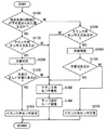
図2を参照して、本実施の形態に係る故障診断装置であるエンジンECU100で実行されるクランク角センサ104の故障を診断するプログラムの構造について説明する。
With reference to FIG. 2, the structure of a program for diagnosing a failure of
ステップ(以下、ステップをSと略して記載する。)1000にて、エンジンECU100は、特定の気筒の燃焼圧が予め定められた値以上か否かを判断する。特定の気筒は、4気筒のうちの予め定められた気筒である。特定の気筒は、たとえば、クランク角センサ104により、タイミングロータ110における欠歯を検知する時に、燃焼圧がピークとなる気筒である。燃焼圧がピークとなる時における特定の気筒の判別は、上述したように4気筒のそれぞれに燃焼圧センサ106を設けることにより判別することができる。本実施の形態において、燃焼圧がピークとなる時とは、燃焼圧が極大値となる時である。極大値となる時は、たとえば、単位時間当たりの燃焼圧の変化量に基づいて求めることができる。
In step (hereinafter, step is abbreviated as S) 1000,
S1100にて、エンジンECU100は、クランク角センサ104からの入力があるか否かを判断する。すなわち、エンジンECU100は、クランク角センサ104から送信されるクランクポジション検知信号を受信するか否かを判断する。クランク角センサ104からの入力があると(S1100にてYES)、処理はS1200に移される。もしそうでないと(S1100にてNO)、処理はS1800に移される。
In S1100,
S1200にて、エンジンECU100は、欠歯判定を行なう。本実施の形態において、欠歯判定は、エンジンECU100において、クランク角センサ104から送信されるクランクポジション検知信号の周期に基づいて行なわれる。
In S1200,
S1300にて、エンジンECU100は、検出された欠歯の位置が正しい位置にあるか否かを判断する。すなわち、エンジンECU100は、クランク角センサ104により検知される欠歯の位置に基づくクランクシャフト108の回転角と、燃焼圧センサ106により検知される燃焼圧が極大値となる燃焼圧のピーク時に対応するクランクシャフト108の回転角との差が予め定められた範囲内か否かを判断する。欠歯が正しい位置にあると(S1300にてYES)、処理はS1400に移される。もしそうでないと(S1300にてNO)、処理はS1800に移される。
In S1300,
S1400にて、エンジンECU100は、クランク角センサ104の動作は正常であると診断する。S1500にて、エンジンECU100は、クランク角センサ104からの入力があるか否かを判断する。クランク角センサ104から入力があると(S1500にてYES)、処理はS1600に移される。もしそうでないと(S1500にてNO)、処理はS1800に移される。
In S1400,
S1600にて、エンジンECU100は、欠歯判定を行なう。欠歯判定は、上述のS1200の欠歯判定と同様である。したがって、詳細な説明は繰返さない。
In S1600,
S1700にて、エンジンECU100は、欠歯判定を行なった結果、欠歯があるか否かを判断する。欠歯があると(S1700にてYES)、処理はS1800に移される。もしそうでないと(S1700にてNO)、処理はS2000に移される。
In S1700,
S1800にて、エンジンECU100はクランク角センサ104の動作に異常があると判定する。すなわち、エンジンECU100はクランク角センサ104が故障していると診断する。
In S1800,
S1900にて、エンジンECU100は、警告ランプを点灯させる。そして、クランク角センサ104の故障に対応する故障コードをメモリに記憶させる。S2000にて、エンジンECU100は、クランク角センサ104の動作は正常であると診断する。
In S1900,
以上のような構造およびフローチャートに基づく、本実施の形態に係る故障診断装置のクランク角センサ104の故障を診断する動作について説明する。
An operation for diagnosing a failure of the
図3(A)〜(F)に示すように、エンジンECU100は、4気筒のそれぞれに設けられた燃焼圧センサ(1)〜(4)の出力信号を検知している。このとき、4気筒のうち、燃焼圧センサ(2)および燃焼圧センサ(3)が設けられる2つの特定の気筒において、燃焼圧が予め定められた値以上となると(S1000にてYES)、クランク角センサ104の入力があるか否かを判断する(S1100)。図3(F)に示すように、各気筒において燃焼圧が予め定められた値以上になると、エンジンECU100は、基準信号を生成する。そして、図3(E)に示すように、各気筒において燃焼圧がピークになると、エンジンECU100は、ピーク信号を生成する。各気筒における燃焼圧が予め定められた値以下であると基準信号およびピーク信号は生成されない。図3(G)に示すように、クランク角センサ104は、タイミングロータ110に設けられた歯部に対応した波形を出力する。このとき、歯と隣接する歯との間においてクランク角センサ104から出力される波形の周期が予め定められた周期以上となることにより、欠歯の位置を検出することができる。
As shown in FIGS. 3A to 3F, the
クランク角センサ104の入力がないと(S1100にてNO)、クランク角センサ104の動作は異常であると判定されて(S1800)、警告ランプが点灯し、故障コードがメモリに記憶される(S1900)。
If there is no input from crank angle sensor 104 (NO in S1100), it is determined that the operation of
クランク角センサ104の入力があると(S1100にてYES)、欠歯判定が行なわれる(S1200)。特定の気筒において、燃焼圧のピーク時に対応する回転角と、クランク角センサ104により検知される欠歯の位置に対応する回転角との差が予め定められた値以下であれば、検知された欠歯の位置が正しいと判断されて(S1300にてYES)、クランク角センサ104の動作は正常であると判定される(S1400)。
If there is an input from crank angle sensor 104 (YES in S1100), missing tooth determination is performed (S1200). In a specific cylinder, if the difference between the rotation angle corresponding to the peak combustion pressure and the rotation angle corresponding to the position of the missing tooth detected by the
なお、欠歯判定は、ピーク信号が生成された時のクランク角センサ104により検知される欠歯の位置の回転角が予め定められた範囲の回転角か否かを判断してもよい。または、エンジンECU100は、特定の気筒における燃焼圧が予め定められた値以上となっている間、すなわち、基準信号が生成されている間に、欠歯を検出することにより、欠歯の位置が正しい位置にあると判断してもよい。
In the missing tooth determination, it may be determined whether the rotation angle of the position of the missing tooth detected by the
検知された欠歯の位置が正しくないと判断されると(S1300にてNO)、クランク角センサ104の動作は異常であると判定される(S1800)。
If it is determined that the position of the detected missing tooth is not correct (NO in S1300), it is determined that the operation of
特定の気筒において、燃焼圧が所定値以下であると(S1000にてNO)、クランク角センサ104の入力があるか否かを判断する(S1500)。ここで、クランク角センサ104の入力がないと(S1500にてNO)、クランク角センサ104の動作は異常であると判定される(S1800)。クランク角センサ104の入力があると(S1500にてYES)、欠歯判定が行なわれる(S1600)。このとき、クランク角センサ104により欠歯に対応する波形が検知されると(S1700にてYES)、クランク角センサ104の動作は異常であると判定されて(S1800)、クランク角センサ104により欠歯に対応する波形が検知されないと(S1700にてNO)、クランク角センサ104の動作は正常であると判定される(S2000)。
If the combustion pressure is not more than a predetermined value in a specific cylinder (NO in S1000), it is determined whether or not there is an input from crank angle sensor 104 (S1500). If there is no input from crank angle sensor 104 (NO in S1500), it is determined that the operation of
以上のようにして、本実施の形態に係る故障診断装置は、エンジンに設けられ、エンジンの燃焼室における燃焼により発生する駆動力により回転するクランクシャフトの回転角を検知するクランク角センサの故障を診断する。そして、故障診断装置は、燃焼室内の圧力を検知するための燃焼圧センサと、燃焼圧センサにより検知される圧力の変化に基づき解析される回転角と、クランク角センサにより検知される回転角とに基づいて、クランクシャフトの回転に伴い変化する物理量の異常を検知して、クランク角センサの故障を診断する。これにより、たとえば、圧力検知手段により検知される圧力が予め定められた値以上となるときに、クランク角センサから予め定められた入力があるか否かを検知する。このとき、予め定められた入力がないとクランク角センサが故障したと診断する。具体的には、複数の気筒を有するエンジンにおいて、気筒内の燃焼による圧力の変化は、クランクシャフトの回転角と対応づけることができる。すなわち、予め定められた気筒において、検知手段により検知される圧力が極大値となる時(たとえば、燃焼圧のピーク時)に基づき解析されるクランクシャフトの回転角と、クランク角センサにより検知される基準となる位置(たとえば、タイミングロータの欠歯位置)に基づくクランクシャフトの回転角とに基づいて、クランク角センサの故障を診断する。このとき、クランク角センサにより検知される回転角と燃焼圧に基づく回転角との差が予め定められた範囲以上となると、クランク角センサが故障したと診断できる。また、複数の気筒を有する場合、それぞれの気筒に対して燃焼圧センサを設けると、それぞれの気筒における燃焼圧を検知できる。そのため、どの気筒がどの行程にあるかを検出することができる。すなわち、気筒判別を行なうことができる。したがって、クランク角センサの異常を正確に検出する故障診断装置を提供することができる。また、燃焼圧センサにより検知される圧力の変化に基づいて、クランク角センサの異常を検出するため、吸気量が少ない場合においても、クランク角センサの異常を検出することができる。 As described above, the failure diagnosis apparatus according to the present embodiment is provided in the engine and detects a failure of the crank angle sensor that detects the rotation angle of the crankshaft that is rotated by the driving force generated by the combustion in the combustion chamber of the engine. Diagnose. The failure diagnosis device includes a combustion pressure sensor for detecting the pressure in the combustion chamber, a rotation angle analyzed based on a change in pressure detected by the combustion pressure sensor, and a rotation angle detected by the crank angle sensor. Based on the above, the abnormality of the physical quantity that changes with the rotation of the crankshaft is detected to diagnose the failure of the crank angle sensor. Thereby, for example, when the pressure detected by the pressure detection means becomes a predetermined value or more, it is detected whether or not there is a predetermined input from the crank angle sensor. At this time, if there is no predetermined input, it is diagnosed that the crank angle sensor has failed. Specifically, in an engine having a plurality of cylinders, a change in pressure due to combustion in the cylinder can be associated with a rotation angle of the crankshaft. That is, in a predetermined cylinder, the rotation angle of the crankshaft analyzed based on the time when the pressure detected by the detection means becomes a maximum value (for example, at the peak of the combustion pressure) and the crank angle sensor. The failure of the crank angle sensor is diagnosed based on the rotation angle of the crankshaft based on the reference position (for example, the timing tooth missing tooth position). At this time, if the difference between the rotation angle detected by the crank angle sensor and the rotation angle based on the combustion pressure is greater than or equal to a predetermined range, it can be diagnosed that the crank angle sensor has failed. Further, when a plurality of cylinders are provided, the combustion pressure in each cylinder can be detected by providing a combustion pressure sensor for each cylinder. Therefore, it is possible to detect which cylinder is in which stroke. That is, cylinder discrimination can be performed. Therefore, it is possible to provide a failure diagnosis device that accurately detects abnormality of the crank angle sensor. Further, since the abnormality of the crank angle sensor is detected based on the change in pressure detected by the combustion pressure sensor, the abnormality of the crank angle sensor can be detected even when the intake air amount is small.
<第2の実施の形態>
以下、第2の実施の形態に係る故障診断装置について説明する。本実施の形態に係る故障診断装置を搭載した車両のエンジンの構成は、第1の実施の形態において説明したエンジン200と同様の構成である。したがって、それらの詳細な説明は繰返さない。
<Second Embodiment>
Hereinafter, the failure diagnosis apparatus according to the second embodiment will be described. The configuration of the vehicle engine equipped with the failure diagnosis apparatus according to the present embodiment is the same as that of
第1の実施の形態に係る故障診断装置は、クランク角センサ104の故障を診断する装置として説明したが本発明はこれに限定されない。本実施の形態に係る故障診断装置は、エンジンに設けられ、エンジンの燃焼室における燃焼により発生する駆動力により回転する軸の状態を検知する装置の故障を診断する。したがって、本実施の形態に係る故障診断装置は、たとえば、カム角センサ102の故障を診断するものであってもよい。
Although the failure diagnosis apparatus according to the first embodiment has been described as an apparatus for diagnosing a failure of the
本実施の形態に係る故障診断装置は、燃焼圧センサ106により検知される燃焼圧の変化に基づき解析されるカムシャフト120の回転角の状態と、カム角センサ102により検知されるカムシャフト120の回転角の状態とに基づいて、カムシャフト120の回転に伴い変化する物理量の異常を検知して、カム角センサ102の故障を診断する。
The failure diagnosis apparatus according to the present embodiment includes the state of the rotation angle of the
具体的には、特定の気筒における燃焼圧の変化と、カム角センサ102からのカムポジション検知信号の入力とを対応づける。すなわち、エンジンECU100は、図3(H)に示すように、特定の気筒(燃焼圧センサ(1)が設けられる気筒)における燃焼圧が予め定められた値以上となってから、次に燃焼する気筒(燃焼圧センサ(2)が設けられる気筒)における燃焼圧が変化するまでの間に、カム角センサ102からカムポジション検知信号の入力が有るか否かでカム角センサ102が故障しているか否かを判断する。
Specifically, the change in the combustion pressure in a specific cylinder is associated with the input of the cam position detection signal from the
図4を参照して、本実施の形態に係る故障診断装置であるエンジンECU100で実行されるカム角センサ102の故障を診断するプログラムの構造について説明する。
With reference to FIG. 4, the structure of a program for diagnosing a failure of
S3000にて、エンジンECU100は、特定の気筒(1)の燃焼圧が予め定められた値以上であるか否かを判断する。ここで、特定の気筒(1)は、4気筒のうちの予め定められた気筒である。特定の気筒(1)の判別は、上述したように4気筒にそれぞれ設けられた燃焼圧センサにより判別することができる。本実施の形態において、特定の気筒(1)は、燃焼圧センサ(1)が設けられる気筒である。特定の気筒(1)の燃焼圧が予め定められた値以上になると(S3000にてYES)、処理はS3100に移される。もしそうでないと(S3000にてNO)、処理はS3300に移される。
In S3000,
S3100にて、エンジンECU100は、特定の気筒(2)の燃焼圧が変化するまでにカム角センサ102の入力があるか否かを判断する。特定の気筒(2)とは、4気筒のうち特定の気筒(1)の次に点火される気筒である。本実施の形態において、特定の気筒(2)は、燃焼圧センサ(2)が設けられる気筒である。エンジンECU100は、特定の気筒(2)の燃焼圧が変化するまでにカム角センサ102から送信されるカムポジション検知信号を受信するか否かを判断する。特定の気筒(2)の燃焼圧が変化するまでにカム角センサ102から入力があると(S3100にてYES)、処理はS3200に移される。もしそうでないと(S3100にてNO)、処理はS3400に移される。S3200にて、エンジンECU100は、カム角センサ102の動作が正常であると判定する。
In S3100,
S3300にて、エンジンECU100は、カム角センサ102の入力があるか否かを判断する。すなわち、エンジンECU100は、カム角センサ102から送信されるカムポジション検知信号を受信するか否かを判断する。カム角センサ102の入力があると(S3300にてYES)、処理はS3400に移される。もしそうでないと(S3300にてNO)、処理はS3600に移される。
In S3300,
S3400にて、エンジンECU100は、カム角センサ102の動作は異常であると判定する。すなわち、カム角センサ102は故障したと診断する。S3500にて、エンジンECU100は、警告ランプを点灯させて、カム角センサ102の故障に対応する故障コードをメモリに記憶させる。S3600にて、エンジンECU100は、カム角センサ102の動作は正常であると判定する。
In S3400,
以上のような構造およびフローチャートに基づく、本実施の形態に係る故障診断装置のカム角センサ102の故障を診断する動作について説明する。
An operation for diagnosing a failure of the
図3(A)に示すような出力波形を示す燃焼圧センサ(1)により検知される燃焼圧が予め定められた値以上となると(S3000にてYES)、図3(B)に示すような出力波形を示す燃焼圧センサ(2)により検知される燃焼圧が変化するまでにカム角センサ102の入力があるか否かを判断される(S3100)。図3(H)に示すようにカム角センサ102の入力があると(S3100にてYES)、カム角センサ102の動作は正常であると判定される(S3200)。カム角センサの入力がないと(S3100にてNO)、カム角センサ102の動作は異常であると判定されて(S3400)、警告ランプが点灯されて、故障コードがメモリに記憶される(S3500)。一方、燃焼圧センサ(1)により検知される燃焼圧が予め定められた値以下であると(S3000にてNO)、カム角センサ102の入力があるか否かが判断される(S3300)。カム角センサ102の入力があると(S3300にてYES)、カム角センサ102の動作は異常であると判定される(S3400)。一方、カム角センサ102の入力がないと(S3300にてNO)、カム角センサ102の動作は正常であると判定される(S3600)。
When the combustion pressure detected by combustion pressure sensor (1) having an output waveform as shown in FIG. 3 (A) exceeds a predetermined value (YES in S3000), as shown in FIG. 3 (B). It is determined whether or not there is an input of the
以上のようにして、本実施の形態に係る故障診断装置は、エンジンに設けられ、エンジンの気筒内における燃焼により発生する駆動力により回転運動するカムシャフトの回転角を検知するカム角センサの故障を診断することができる。 As described above, the failure diagnosis device according to the present embodiment is provided with the engine, and the failure of the cam angle sensor that detects the rotation angle of the camshaft that rotates by the driving force generated by the combustion in the cylinder of the engine. Can be diagnosed.
今回開示された実施の形態はすべての点で例示であって制限的なものではないと考えられるべきである。本発明の範囲は上記した説明ではなくて特許請求の範囲によって示され、特許請求の範囲と均等の意味および範囲内でのすべての変更が含まれることが意図される。 The embodiment disclosed this time should be considered as illustrative in all points and not restrictive. The scope of the present invention is defined by the terms of the claims, rather than the description above, and is intended to include any modifications within the scope and meaning equivalent to the terms of the claims.
100 エンジンECU、102 カム角センサ、104 クランク角センサ、106 燃焼圧センサ、108 クランクシャフト、110 タイミングロータ、112 ピストン、114 燃焼室、116 吸気経路、118 排気経路、120,122 カムシャフト、200 エンジン。
DESCRIPTION OF
Claims (5)
前記燃焼室内の圧力を検知するための圧力検知手段と、
前記圧力検知手段により検知される圧力の変化に基づき解析される軸の状態と、前記検知装置により検知される前記軸の状態とに基づいて、前記軸の回転に伴い変化する物理量の異常を検知して、前記検知装置の故障を診断するための診断手段とを含む、故障診断装置。 A failure diagnosis device that diagnoses a failure of a detection device that is provided in an engine and detects a state of a shaft that rotates by a driving force generated by combustion in a combustion chamber of the engine,
Pressure detecting means for detecting the pressure in the combustion chamber;
Based on the state of the shaft analyzed based on the change in pressure detected by the pressure detection means and the state of the shaft detected by the detection device, an abnormality in the physical quantity that changes as the shaft rotates is detected. And a diagnosis means for diagnosing a failure of the detection device.
前記軸の状態は、軸の回転角の状態であって、
前記診断手段は、前記複数の気筒のうち、予め定められた気筒において、前記圧力検知手段により検知される圧力が予め定められた圧力以上になると、前記圧力の変化に基づく回転角と、前記検知装置により検知される回転角とに基づいて、前記検知装置の故障を診断するための手段を含む、請求項1に記載の故障診断装置。 The engine has a plurality of cylinders,
The state of the shaft is a state of the rotation angle of the shaft,
The diagnosis means is configured to detect a rotation angle based on a change in the pressure and the detection when a pressure detected by the pressure detection means is equal to or higher than a predetermined pressure in a predetermined cylinder among the plurality of cylinders. The failure diagnosis apparatus according to claim 1, further comprising means for diagnosing a failure of the detection device based on a rotation angle detected by the device.
Priority Applications (4)
| Application Number | Priority Date | Filing Date | Title |
|---|---|---|---|
| JP2004009414A JP2005201174A (en) | 2004-01-16 | 2004-01-16 | Failure diagnostic device |
| CN200510000306.8A CN1641199A (en) | 2004-01-16 | 2005-01-06 | Fault diagnosis device for detection device provided on engine |
| EP05000422A EP1555415A3 (en) | 2004-01-16 | 2005-01-11 | Fault diagnosis device for detection device provided on engine |
| US11/035,104 US20050159877A1 (en) | 2004-01-16 | 2005-01-14 | Fault diagnosis device for detection device provided on engine |
Applications Claiming Priority (1)
| Application Number | Priority Date | Filing Date | Title |
|---|---|---|---|
| JP2004009414A JP2005201174A (en) | 2004-01-16 | 2004-01-16 | Failure diagnostic device |
Publications (1)
| Publication Number | Publication Date |
|---|---|
| JP2005201174A true JP2005201174A (en) | 2005-07-28 |
Family
ID=34616914
Family Applications (1)
| Application Number | Title | Priority Date | Filing Date |
|---|---|---|---|
| JP2004009414A Withdrawn JP2005201174A (en) | 2004-01-16 | 2004-01-16 | Failure diagnostic device |
Country Status (4)
| Country | Link |
|---|---|
| US (1) | US20050159877A1 (en) |
| EP (1) | EP1555415A3 (en) |
| JP (1) | JP2005201174A (en) |
| CN (1) | CN1641199A (en) |
Families Citing this family (12)
| Publication number | Priority date | Publication date | Assignee | Title |
|---|---|---|---|---|
| US7660662B2 (en) * | 2006-12-28 | 2010-02-09 | Detroit Diesel Corporation | Fault code memory administrator with a driving cycle state machine concept |
| WO2008109642A1 (en) * | 2007-03-06 | 2008-09-12 | Gm Global Technology Operations, Inc. | Method and apparatus for determining a parameter for normalized instantaneous heat release in an internal combustion engine |
| JP4697201B2 (en) * | 2007-07-19 | 2011-06-08 | トヨタ自動車株式会社 | Abnormality detection device for internal combustion engine |
| JP4599390B2 (en) * | 2007-12-14 | 2010-12-15 | 三菱重工業株式会社 | Micro pilot injection gas engine |
| US8301362B2 (en) * | 2009-03-27 | 2012-10-30 | GM Global Technology Operations LLC | Method and system for generating a diagnostic signal of an engine component using an in-cylinder pressure sensor |
| DE102009027400A1 (en) | 2009-07-01 | 2011-01-05 | Robert Bosch Gmbh | Method for diagnosing a sensor device of an internal combustion engine |
| JP5195738B2 (en) * | 2009-12-24 | 2013-05-15 | トヨタ自動車株式会社 | Rotation sensor abnormality determination device |
| CN102116809B (en) * | 2009-12-30 | 2014-08-13 | 中国第一汽车集团公司 | Method for diagnosing phase sensor |
| CN102175459B (en) * | 2011-01-28 | 2012-11-21 | 南京航空航天大学 | Automatic measurement and control device for test bench of combustion chamber of micro engine |
| US9194321B1 (en) * | 2014-08-27 | 2015-11-24 | GM Global Technology Operations LLC | System and method for diagnosing a fault in a camshaft position sensor and/or a crankshaft position sensor |
| SE539262C2 (en) | 2015-10-16 | 2017-06-07 | Scania Cv Ab | Method and system for diagnosing a crankshaft rotational position sensor unit of a crankshaft |
| CN111238958A (en) * | 2020-01-22 | 2020-06-05 | 上海电力大学 | Rotating machinery bending fault detection device |
Family Cites Families (10)
| Publication number | Priority date | Publication date | Assignee | Title |
|---|---|---|---|---|
| JPS58197452A (en) | 1982-05-13 | 1983-11-17 | Nissan Motor Co Ltd | Electronic controller for internal-combustion engine |
| JPS639679A (en) * | 1986-06-28 | 1988-01-16 | Honda Motor Co Ltd | Control of ignition timing of internal combustion engine |
| WO1992013183A1 (en) * | 1991-01-24 | 1992-08-06 | Siemens Aktiengesellschaft | Device for detecting faulty firing in an internal-combustion engine |
| DE4306252C1 (en) * | 1993-03-01 | 1994-05-19 | Daimler Benz Ag | Operating system for multi-cylinder engine with fuel injection - uses signal from pressure sensor for high pressure fuel supply line for emergency engine operating mode |
| JPH0828338A (en) * | 1994-07-11 | 1996-01-30 | Unisia Jecs Corp | Crank angle position detecting device for internal combustion engine and control device |
| JP3904621B2 (en) * | 1995-08-29 | 2007-04-11 | 三菱電機株式会社 | Crank angle sensor abnormality detection device |
| DE19713182A1 (en) * | 1997-03-27 | 1998-10-01 | Siemens Ag | Method of determining engine revs. of motor vehicle for engine testing esp. exhaust gas testing |
| JP3775220B2 (en) * | 2000-12-27 | 2006-05-17 | 株式会社デンソー | Control device for internal combustion engine |
| US20020092499A1 (en) * | 2001-01-12 | 2002-07-18 | Kargilis John S. | Detonation sensing of crankshaft position |
| JP2004009414A (en) | 2002-06-05 | 2004-01-15 | Canon Inc | Electronic device |
-
2004
- 2004-01-16 JP JP2004009414A patent/JP2005201174A/en not_active Withdrawn
-
2005
- 2005-01-06 CN CN200510000306.8A patent/CN1641199A/en active Pending
- 2005-01-11 EP EP05000422A patent/EP1555415A3/en not_active Withdrawn
- 2005-01-14 US US11/035,104 patent/US20050159877A1/en not_active Abandoned
Also Published As
| Publication number | Publication date |
|---|---|
| CN1641199A (en) | 2005-07-20 |
| EP1555415A2 (en) | 2005-07-20 |
| EP1555415A3 (en) | 2006-11-02 |
| US20050159877A1 (en) | 2005-07-21 |
Similar Documents
| Publication | Publication Date | Title |
|---|---|---|
| EP1555415A2 (en) | Fault diagnosis device for detection device provided on engine | |
| KR100572132B1 (en) | Methods to determine the phase angle of a four stroke internal combustion engine with an odd number of cylinders | |
| KR101775387B1 (en) | Method and control unit for controlling an internal combustion engine | |
| US8204674B2 (en) | Apparatus for controlling engine using crank signal and cam signal | |
| JP4202370B2 (en) | Control device for internal combustion engine | |
| KR101795306B1 (en) | Starting control method for a vehicle | |
| JP2011069282A (en) | Abnormality diagnostic device for crank angle detection system | |
| US20080125957A1 (en) | Method of operating an internal combustion engine, in particular in a motor vehicle | |
| JP6539747B2 (en) | Cam angle sensor abnormality diagnosis device for straddle type vehicle, engine system, and straddle type vehicle | |
| JPH08277744A (en) | Internal combustion engine controller | |
| KR20090062389A (en) | Method for driving engine by position of crankshaft and camshaft | |
| JP4615004B2 (en) | Method and apparatus for discriminating rotation direction of rotating body, and control device for internal combustion engine using the apparatus | |
| JP4521661B2 (en) | Cylinder discrimination device for internal combustion engine | |
| JP2008309038A (en) | Stroke determination method and stroke determination device for single cylinder engine | |
| JPH07310585A (en) | Diagnostic device for cylinder internal pressure sensor | |
| KR101897559B1 (en) | Control method of fuel injection during synchronization error | |
| US7047127B2 (en) | Method and device for determining the initial angle position of an internal combustion engine | |
| KR101869317B1 (en) | Method for detecting synchronization error | |
| JP2009235963A (en) | Method and device for detecting crank angle of engine | |
| JP2009236003A (en) | Abnormality diagnosing device for crank angle sensor | |
| JP3963054B2 (en) | Rotation signal abnormality detection device | |
| JP4207486B2 (en) | Diagnostic method and diagnostic apparatus for internal combustion engine | |
| JP7291238B2 (en) | Engine control device and engine control method | |
| JP5737205B2 (en) | In-cylinder pressure sensor abnormality diagnosis device | |
| KR100748649B1 (en) | Cam tooth matching diagnosis device of vehicle and method thereof |
Legal Events
| Date | Code | Title | Description |
|---|---|---|---|
| A761 | Written withdrawal of application |
Free format text: JAPANESE INTERMEDIATE CODE: A761 Effective date: 20070326 |