JP2005201030A - Column to be fixed on handrail wall of veranda, fence fixed by using this column and temporary scaffold for work - Google Patents
Column to be fixed on handrail wall of veranda, fence fixed by using this column and temporary scaffold for work Download PDFInfo
- Publication number
- JP2005201030A JP2005201030A JP2004040602A JP2004040602A JP2005201030A JP 2005201030 A JP2005201030 A JP 2005201030A JP 2004040602 A JP2004040602 A JP 2004040602A JP 2004040602 A JP2004040602 A JP 2004040602A JP 2005201030 A JP2005201030 A JP 2005201030A
- Authority
- JP
- Japan
- Prior art keywords
- handrail wall
- fixed
- veranda
- fence
- metal fitting
- Prior art date
- Legal status (The legal status is an assumption and is not a legal conclusion. Google has not performed a legal analysis and makes no representation as to the accuracy of the status listed.)
- Pending
Links
Images


Abstract
Description
本発明は所謂マンション等の集合住宅のベランダや廊下の手摺壁に防犯用フェンス、防鳥用網やガーデニング用トレリス等を取り付けるために、着脱可能に立設する支柱に関し、また該支柱取付用フレーム金具に工事用仮設足場を取り付ける足場組立工法に関する。 The present invention relates to a column that can be detachably installed in order to attach a crime prevention fence, a bird net, a gardening trellis, etc. to a veranda of a housing complex such as a condominium or a handrail wall in a hallway, and the column mounting frame The present invention relates to a scaffold assembly method for attaching a temporary scaffold for construction to a metal fitting.
従来、所謂マンション等の集合住宅のベランダや廊下の手摺壁に防犯用フェンス、防鳥用網やガーデニング用トレリス等を取り付けるためには、ベランダ等の手摺壁にアンカーボルトを打ち込み、これに支柱を固定して、該支柱を利用して防犯用フェンス、防鳥用網やガーデニング用トレリス等を取り付ける必要があった。 Conventionally, in order to attach security fences, bird nets, gardening trellises, etc. to verandas of apartment buildings such as so-called condominiums and corridor handrail walls, anchor bolts have been driven into handrail walls of verandas, etc. It is necessary to fix and attach a security fence, a bird net, a gardening trellis, etc. using the support.
またマンション等の集合住宅の大規模修繕の際に、建物の外壁を補修するために、外壁全面に沿って工事用仮設足場を組み立てる必要がある。工事用架設足場は一般に多数の鋼管を各種の結合金具で互に結合して組み立てるのであるが、鋼管足場を建物の外壁に固定するために、タイル壁の場合は、多数の必要箇所のタイルを一旦剥離して、その剥離跡のコンクリート壁にアンカーボルトを打ち込んで、これに足場を固定し、工事終了後に足場を解体する際に、アンカーボルトを抜去して、タイルを張り直すことが行われている。 In addition, in order to repair the outer wall of a building during a large-scale repair of an apartment house such as a condominium, it is necessary to assemble a temporary scaffold for construction along the entire outer wall. Construction scaffolds are generally assembled by joining many steel pipes to each other with various fittings, but in order to secure the steel pipe scaffolds to the outer wall of the building, in the case of tile walls, many necessary tiles are placed. Once peeled off, anchor bolts are driven into the concrete wall of the peeling trace, the scaffolding is fixed to this, and when the scaffolding is dismantled after completion of construction, the anchor bolts are removed and the tiles are re-stretched. ing.
上記のように、従来のコンクリート造りの集合住宅のベランダや廊下の手摺壁に、種々の必要に応じて、支柱を立設しようとすると、安全確実に固定するためには、アンカーボルトを打ち込んで、これに支柱を固定する必要があり、手摺壁に傷を付ける結果となり、賃貸住宅では賃借人が勝手に行うことはできなかった。 As mentioned above, when you try to erect a pillar on the veranda of a conventional concrete apartment house or a handrail wall in a hallway, if you want to stand upright, you need to drive anchor bolts to secure it securely It was necessary to fix the column to this, which resulted in scratching the handrail wall, and the renter could not do it without permission in the rental housing.
またマンション等の補修工事の際、工事用仮設足場を固定するために、一旦タイルを剥離してアンカーボルトで足場を固定し、工事終了後にタイルの復旧工事をする必要があった。 In addition, when repairing a condominium, etc., it was necessary to peel the tiles once and fix the scaffolds with anchor bolts in order to fix the temporary scaffolding for the construction, and to restore the tiles after the construction was completed.
従って本発明は、集合住宅等のベランダ等のコンクリート製手摺壁等に支柱を着脱自在に立設することができ、その際に手摺壁等に傷を付ける虞のない、ベランダ等の手摺壁に固定用の支柱を提供することを目的とする。 Therefore, the present invention can detachably attach a column to a concrete handrail wall such as a veranda of an apartment house, etc., and there is no risk of scratching the handrail wall at that time. The purpose is to provide a fixing column.
また本発明の他の目的はコンクリート造りの集合住宅等の外壁の補修の際に、工事用仮設足場を簡単に組むことができる足場組立工法を提供することを目的とする。 Another object of the present invention is to provide a scaffold assembly method capable of easily assembling a temporary scaffold for construction when repairing an outer wall of a concrete apartment house or the like.
上記目的を達成すべく、本発明者は鋭意研究を重ねた結果、コンクリート製の手摺壁を跨ぐような全体がコ字状のフレーム金具を手摺壁の内外から締めつけて手摺壁に挟着することにより、フレーム金具を着脱可能に手摺壁に固定することができ、該フレーム金具の手摺壁上縁に当接する部分に、支柱を固着、立設することにより、ベランダ等の手摺壁に支柱を着脱自在に固定することができることを見出し、本発明を完成するに到った。 In order to achieve the above-mentioned object, the present inventor has conducted extensive research, and as a result, the entire U-shaped frame fitting straddling the concrete handrail wall is fastened from inside and outside of the handrail wall and clamped to the handrail wall. The frame bracket can be detachably fixed to the handrail wall, and the column is fixed to the portion of the frame bracket that comes into contact with the upper edge of the handrail wall. The inventors have found that they can be freely fixed and have completed the present invention.
即ち、本発明は、コンクリート製の手摺壁を跨ぐような全体がコ字状のフレーム金具と、手摺壁を跨いだ該フレーム金具を着脱可能に該手摺壁の内外から該手摺壁を挟むように挟着固定する固定手段と、該フレーム金具の手摺壁上縁に当接する部分に固着して立設された支柱を備えたベランダ等の手摺壁に固定用の支柱を要旨とする。 That is, the present invention is configured so that the entire U-shaped frame bracket straddling a concrete handrail wall and the frame bracket straddling the handrail wall are detachably sandwiched between the inside and outside of the handrail wall. The gist of the present invention is a supporting column for fixing to a handrail wall such as a veranda provided with a fixing means for sandwiching and fixing and a column that is fixedly installed on a portion of the frame metal fitting that is in contact with the upper edge of the handrail wall.
他の本発明は、上記のベランダ等の手摺壁に固定用の支柱において、該コの字状フレーム金具が一対の逆L字状取付フレームを互に対向して設け、その間隔を調節可能に固定したコの字状フレーム金具であるベランダ等の手摺壁に固定用の支柱を要旨とする。 In another aspect of the present invention, the U-shaped frame metal fitting is provided with a pair of inverted L-shaped mounting frames facing each other in the support column fixed to the handrail wall such as a veranda, and the interval between the brackets can be adjusted. The gist is a support column for fixing to a handrail wall such as a veranda which is a fixed U-shaped frame metal fitting.
更に他の本発明は、上記のベランダ等の手摺壁に固定用の支柱において、該固定手段が該コの字状フレーム金具の脚部に螺合して、先端が該手摺壁の側面に当接して圧接するようにねじ込まれたボルトよりなるベランダ等の手摺壁に固定用の支柱を要旨とする。 In still another aspect of the present invention, in the post for fixing to the handrail wall such as a veranda, the fixing means is screwed into the leg portion of the U-shaped frame metal fitting, and the tip contacts the side surface of the handrail wall. The gist is a support column for fixing to a handrail wall such as a veranda composed of bolts screwed so as to come into pressure contact with each other.
更に他の本発明は、上記のベランダ等の手摺壁に固定用の支柱にフェンスの枠体を固定し、該支柱の間のベランダ等の手摺壁上に固定した、枠体を備えたフェンスを要旨とする。 Still another aspect of the present invention is to provide a fence including a frame body, wherein a fence frame is fixed to a fixing column on a handrail wall such as a veranda, and is fixed on a handrail wall such as a veranda between the columns. The gist.
更に他の本発明は、上記のベランダ等の手摺壁に固定用の支柱に固定した該フェンスが防鳥網よりなるフェンスであるベランダ等の手摺壁上に固定した、枠体を備えたフェンスを要旨とする。 Still another aspect of the present invention provides a fence provided with a frame body, wherein the fence fixed to a railing wall such as a veranda is fixed on a railing wall such as a veranda, which is a fence made of a bird net. The gist.
更に他の本発明は、上記のベランダ等の手摺壁に固定用の支柱に固定した該フェンスが防犯用、落下防止用金網、目隠し用鎧戸又は園芸用トレリスよりなるフェンスであるベランダ等の手摺壁上に固定した、枠体を備えたフェンスを要旨とする。 Still another aspect of the present invention is a handrail wall such as a veranda in which the fence fixed to a handrail wall such as a veranda is a fence made of a crime prevention, fall prevention wire mesh, a blindfolding armor door, or a gardening trellis. The gist is a fence with a frame fixed on top.
更に他の本発明は、上記のベランダ等の手摺壁に固定用の支柱の該コの字状フレーム金具の脚部から該手摺壁の外側側方に突出するように固定された部材により、手摺壁に対して揺動不能に固定された工事用仮設足場を要旨とする。 Still another aspect of the present invention provides a handrail by a member fixed so as to protrude from the leg portion of the U-shaped frame metal fitting of the fixing column to the handrail wall such as the above-described veranda. The gist is a temporary scaffold for construction that is fixed to the wall so that it cannot swing.
本発明によれば、コの字状フレーム金具を、ベランダ等のコンクリート製手摺壁を跨ぐように着脱自在に固着することができ、そのフレーム金具に立設した支柱が手摺壁の上に、着脱自在に立設されるので、この支柱を利用して、防犯用金網、防鳥用網やガーデニング用トレリス等を確実に取り付けることができ、また該フレーム金具に固定したボルト等を利用して、工事用仮設足場を確実に固定しうる。 According to the present invention, a U-shaped frame metal fitting can be detachably fixed so as to straddle a concrete handrail wall such as a veranda, and a column erected on the frame metal fitting is attached to and detached from the handrail wall. Since it is set up freely, it is possible to securely attach a security wire net, a bird net, a gardening trellis, etc. using this support, and using bolts etc. fixed to the frame bracket, The temporary scaffold for construction can be securely fixed.
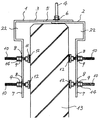
次に本発明の内容を図面により詳細に説明する。図1は本発明に用いられるコの字状フレーム金具の側面図、図2は同正面図、図3は同平面図である。図1に示すコの字状フレーム金具1では、フレーム金具1は2個1組の略逆L字状取付フレーム2、3よりなり、取付フレーム2の上面にボルト4が溶接されている。取付フレーム3の上面には、取付フレーム3上面の長手方向に沿って長孔5が穿設され、この長孔5にボルト4が挿通されて、一対の取付フレーム2、3の相互の間隔を調節してボルト4をナット6で締め付けることにより取付フレーム2、3の間隔を適宜調節して固定する。 Next, the contents of the present invention will be described in detail with reference to the drawings. 1 is a side view of a U-shaped frame metal fitting used in the present invention, FIG. 2 is a front view thereof, and FIG. 3 is a plan view thereof. In the U-shaped frame metal fitting 1 shown in FIG. 1, the frame metal fitting 1 is composed of a set of two substantially inverted L-
コの字状フレーム金具1の両脚部7には、それぞれ複数のボルト挿通孔8を設け、該ボルト挿通孔8に一致する位置にナット9を溶接する。該ナット9にそれぞれ内側よりボルト10を螺合し、該ボルト10の頭の頂面11に硬質ゴム板12を接着する。 A plurality of
ボルト10を回動して、ボルト10の頭の頂面11の硬質ゴム板12を手摺壁13の側面に当接して圧接させることにより、コの字状フレーム金具1が手摺壁13に着脱自在に固着される。ボルト10が緩まないように、固定用二重ナット14で締め付けて置くのが望ましい。 The U-shaped frame metal fitting 1 is detachably attached to the
コの字状フレーム金具1には、図1に示すように、取付フレーム2、3の逆L字状の屈折角部のすぐ下の部分に、横に張り出す膨らみ部22を設けてあるが、これは手摺壁13の中には、手摺壁13の頂部の幅が手摺壁13の下部の本体部分の厚みよりも僅かに幅広く形成されているものがあり、これに対応して手摺壁13頂部の幅廣の部分を膨らみ部22に収容しうるようにしたものである。 As shown in FIG. 1, the U-shaped frame metal fitting 1 is provided with a bulging
図1乃至3に示すコの字状フレーム金具1は一対の逆L字状取付フレーム2、3を互いに摺動して間隔を調節、固定できるようになっているが、必ずしも一対の逆L字状取付フレーム2、3によりコの字状フレーム金具1を構成する必要はない。全体を略コの字状の一体のフレーム金具で構成してもよい。その場合はコの字状フレーム金具1の両脚部7の間隔は一定不変であるが、通常の手摺壁の厚みに適合するように、何種類かのフレーム金具1を用意しておけばよい。この場合はコの字状フレーム金具1の上面にボルト4を溶接する。 The U-shaped frame metal fitting 1 shown in FIGS. 1 to 3 is configured such that a pair of inverted L-
図2に示すように、コの字状フレーム金具1の上に支柱15を固着する。支柱15は金属製パイプよりなり、下端より一定の高さの位置に底板16を設け、該底板16中央にボルト孔を穿け、これにナット17を溶接してある。コの字状フレーム金具1の上面から突出するボルト4に、ナット17を螺合して支柱15全体と共に回動して、締結することにより、支柱15をコの字状フレーム金具1上に立設する。 As shown in FIG. 2, a
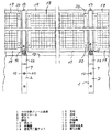
図4は支柱15に防鳥網18を取り付けた状態の正面図である。防鳥網18はアルミニュウム製等の枠体19に20mm程度の網目の金網又は繊維製網を張設したものを用いる。支柱15に防鳥網18を固着する方法は、図4に示すように、支柱15を防鳥網18の幅に合わせて一定間隔に立設し、各支柱15の両側に固定用金具20を突設し、これに防鳥網18を締結する。 FIG. 4 is a front view of the state in which the
支柱15に防鳥網18を取り付ける方法は、図4に示す固定用金具20の代わりに、図5に示すように肘壺21を用いることもできる。肘壺21を用いると、火災等の災害時に消防隊等の進入に際して、必要に応じて容易に防鳥網18を持ち上げて、取り外すことができる。 As a method of attaching the bird net 18 to the
上記防鳥網18の代わりに防犯用のフェンスや、ベランダ等からの物体の落下防止用金網、ベランダ園芸用トレリス、目隠し用鎧戸等を防鳥網18と同様に枠体19を備えた構造に構成して、同様に支柱15に取り付けられる。 Instead of the
またコの字状フレーム金具1から横に突出するボルト10を利用して、ベランダ等の手摺壁13の内側にフラワーボックス等を架設する架台を固定することもできる。 Further, by using
更にコの字状フレーム金具1から手摺壁13の外側に横に突出するボルト10を利用して、工事用仮設足場の鋼管を手摺壁13に固定することができる。建物の補修工事の際に足場を仮設したとき、足場を見知らぬ作業員が往来することに対し、また作業員がいない夜間に足場を伝って不法侵入者が侵入しないかと不安に感ずる住人が多いが、足場の仮設の際に、同時に防犯用金網を支柱15間に張設すれば、住人の不安を解消し、防犯上の安全を図ることができる。 Furthermore, the steel pipe of the temporary scaffold for construction can be fixed to the
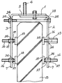
図6は本発明のコの字状フレーム金具1の別の実施例を示す。一対の逆L字状金具よりなる取付フレーム2、3によりコの字状フレーム金具1が構成されているのは、図1と同様である。取付フレーム2及び3の脚部7、7には、その上端近傍と中央部と下端近傍にそれぞれボルトを遊嵌するボルト孔24を設ける。 FIG. 6 shows another embodiment of the U-shaped frame metal fitting 1 of the present invention. The U-shaped frame metal fitting 1 is composed of the mounting
取付フレーム2の脚部7中央のボルト孔24の外側には、長い雌ねじ孔を有する長ナット23が溶接されている。各ボルト孔24には、頭部に硬質ゴム製のパッド25を有する押圧ボルト26を内側より挿通し、脚部7の両側より固定用ナット27により、押圧ボルト26を適宜位置に調節固定する。長ナット23を溶接したボルト孔24に挿通した押圧ボルト26は押圧ボルト26を長ナット23に螺合することにより位置調節をする。 A
脚部7、7の上端部のボルト孔24、24に、1本の長ボルト28を挿通して、その先端に螺合したナット29を締め付けることにより、取付フレーム2、3の脚部7、7の間隔を狭めるように加圧し、各押圧ボルト26のゴム製パッド25を強力な押圧力で手摺壁13の両側面に押圧して、コの字状フレーム金具1全体を強固に手摺壁13に固定する。 By inserting one
長ナット23の雌ねじ孔には、外側よりボルトを螺着して、工事用仮設足場の固定等の目的に用いられる。 Bolts are screwed into the female screw holes of the
本発明のベランダの手摺壁に固定用の支柱及びその支柱を用いて固定したフエンス、及び工事用仮設足場は、マンション等の集合住宅の住環境を改善することができ、鳩、烏、雀等の鳥類がベランダや廊下に飛来して、手摺壁の上に止まり、糞をまき散らす等の糞公害を防止することができる。集合住宅等への不法侵入者等の侵入を防止し、防犯効果を発揮する。 The support pillar fixed to the handrail wall of the veranda of the present invention, the fence fixed by using the support pillar, and the temporary scaffold for construction can improve the living environment of the apartment house such as an apartment, such as a pigeon, a kite, and a sparrow The birds can fly to the veranda or corridor, stop on the handrail wall, and prevent the feces from being polluted. Prevents illegal intruders from entering apartment buildings, etc., and exhibits crime prevention effects.
またマンション等の外壁の補修工事の際、工事用仮設足場を容易に、安全な状態に組み立てることができ、補修工事の際の時間と費用を節減しうる。 In addition, when repairing an outer wall of an apartment, the temporary scaffold for construction can be easily assembled in a safe state, and the time and cost for the repair work can be saved.
1 コの字状フレーム金具
2、3 取付フレーム
4 ボルト
5 長孔
6 ナット
7 脚部
8 ボルト挿通孔
9 ナット
10 ボルト
11 頂面
12 硬質ゴム板
13 手摺壁
14 固定用二重ナット
15 支柱
16 底板
17 ナット
18 防鳥網
19 枠体
20 固定用金具
21 肘壺
22 膨らみ部
23 長ナット
24 ボルト孔
25 パッド
26 押圧ボルト
27 固定用ナット
28 長ボルト
29 ナットDESCRIPTION OF SYMBOLS 1 U-shaped
Claims (7)
Priority Applications (1)
| Application Number | Priority Date | Filing Date | Title |
|---|---|---|---|
| JP2004040602A JP2005201030A (en) | 2004-01-15 | 2004-01-15 | Column to be fixed on handrail wall of veranda, fence fixed by using this column and temporary scaffold for work |
Applications Claiming Priority (1)
| Application Number | Priority Date | Filing Date | Title |
|---|---|---|---|
| JP2004040602A JP2005201030A (en) | 2004-01-15 | 2004-01-15 | Column to be fixed on handrail wall of veranda, fence fixed by using this column and temporary scaffold for work |
Publications (1)
| Publication Number | Publication Date |
|---|---|
| JP2005201030A true JP2005201030A (en) | 2005-07-28 |
Family
ID=34824472
Family Applications (1)
| Application Number | Title | Priority Date | Filing Date |
|---|---|---|---|
| JP2004040602A Pending JP2005201030A (en) | 2004-01-15 | 2004-01-15 | Column to be fixed on handrail wall of veranda, fence fixed by using this column and temporary scaffold for work |
Country Status (1)
| Country | Link |
|---|---|
| JP (1) | JP2005201030A (en) |
Cited By (6)
| Publication number | Priority date | Publication date | Assignee | Title |
|---|---|---|---|---|
| JP2008280745A (en) * | 2007-05-10 | 2008-11-20 | Matsumura Sangyo Kk | Base stand for temporary scaffolding |
| JP2010059632A (en) * | 2008-09-02 | 2010-03-18 | Resin Corp | Suspended scaffolding |
| JP4599458B1 (en) * | 2009-11-18 | 2010-12-15 | 株式会社西三ビケ | Railing wall fasteners |
| JP2016160663A (en) * | 2015-03-02 | 2016-09-05 | 株式会社杉孝 | Guard post |
| JP2016191203A (en) * | 2015-03-30 | 2016-11-10 | Jfeエンジニアリング株式会社 | Mounting structure of outer plate to rigid guard fence |
| JP2016191205A (en) * | 2015-03-30 | 2016-11-10 | Jfeエンジニアリング株式会社 | Reinforcement structure of rigid guard fence |
Citations (8)
| Publication number | Priority date | Publication date | Assignee | Title |
|---|---|---|---|---|
| JPH0445833U (en) * | 1990-08-24 | 1992-04-17 | ||
| JP3034570U (en) * | 1996-08-09 | 1997-02-25 | 小寺工業株式会社 | Handrail support device |
| JPH11140970A (en) * | 1997-11-05 | 1999-05-25 | Toyohisa Nakahara | Fall guard fence |
| JP2000110229A (en) * | 1998-10-01 | 2000-04-18 | Kazahaya Kk | Bird net |
| JP2000189339A (en) * | 1998-12-28 | 2000-07-11 | Ritsuchieru:Kk | Hand rail attaching structure for bath tub |
| JP3083493U (en) * | 2001-07-18 | 2002-01-31 | 株式会社保安資材 | Parapet handrail |
| JP2003082848A (en) * | 2001-09-11 | 2003-03-19 | Tsutsunaka Sheet Bosui Kk | Simple hanging scaffolding device |
| JP2003138644A (en) * | 2001-11-05 | 2003-05-14 | Tateyama Alum Ind Co Ltd | Movable covering device |
-
2004
- 2004-01-15 JP JP2004040602A patent/JP2005201030A/en active Pending
Patent Citations (8)
| Publication number | Priority date | Publication date | Assignee | Title |
|---|---|---|---|---|
| JPH0445833U (en) * | 1990-08-24 | 1992-04-17 | ||
| JP3034570U (en) * | 1996-08-09 | 1997-02-25 | 小寺工業株式会社 | Handrail support device |
| JPH11140970A (en) * | 1997-11-05 | 1999-05-25 | Toyohisa Nakahara | Fall guard fence |
| JP2000110229A (en) * | 1998-10-01 | 2000-04-18 | Kazahaya Kk | Bird net |
| JP2000189339A (en) * | 1998-12-28 | 2000-07-11 | Ritsuchieru:Kk | Hand rail attaching structure for bath tub |
| JP3083493U (en) * | 2001-07-18 | 2002-01-31 | 株式会社保安資材 | Parapet handrail |
| JP2003082848A (en) * | 2001-09-11 | 2003-03-19 | Tsutsunaka Sheet Bosui Kk | Simple hanging scaffolding device |
| JP2003138644A (en) * | 2001-11-05 | 2003-05-14 | Tateyama Alum Ind Co Ltd | Movable covering device |
Cited By (8)
| Publication number | Priority date | Publication date | Assignee | Title |
|---|---|---|---|---|
| JP2008280745A (en) * | 2007-05-10 | 2008-11-20 | Matsumura Sangyo Kk | Base stand for temporary scaffolding |
| JP2010059632A (en) * | 2008-09-02 | 2010-03-18 | Resin Corp | Suspended scaffolding |
| JP4574705B2 (en) * | 2008-09-02 | 2010-11-04 | 株式会社レジン | Suspended scaffolding |
| JP4599458B1 (en) * | 2009-11-18 | 2010-12-15 | 株式会社西三ビケ | Railing wall fasteners |
| JP2011106174A (en) * | 2009-11-18 | 2011-06-02 | Seisan Bike:Kk | Fixing implement for balustrade wall |
| JP2016160663A (en) * | 2015-03-02 | 2016-09-05 | 株式会社杉孝 | Guard post |
| JP2016191203A (en) * | 2015-03-30 | 2016-11-10 | Jfeエンジニアリング株式会社 | Mounting structure of outer plate to rigid guard fence |
| JP2016191205A (en) * | 2015-03-30 | 2016-11-10 | Jfeエンジニアリング株式会社 | Reinforcement structure of rigid guard fence |
Similar Documents
| Publication | Publication Date | Title |
|---|---|---|
| US6422345B1 (en) | Dismountable facade scaffold | |
| US20080157046A1 (en) | Reusable fall restrain supports and fall arrestor | |
| AU2012239144B2 (en) | A guardrail and method for assembling it | |
| CA2534487A1 (en) | Roof edge fall protection apparatus | |
| US20160201313A1 (en) | High-rise architectural structure and maintenance method therefor | |
| JP2005201030A (en) | Column to be fixed on handrail wall of veranda, fence fixed by using this column and temporary scaffold for work | |
| US20140332745A1 (en) | Railing member attachment system and method | |
| KR20200098233A (en) | Safe apparatus for preventing fall | |
| US20160108616A1 (en) | High-rise architectural structure and maintenance method therefor | |
| JP2510380B2 (en) | Fixtures for work scaffolding of unit building | |
| JP2006200164A (en) | Light metal handrail | |
| JP2007107180A (en) | Snow falling protective fence | |
| KR100711588B1 (en) | Falling water prevention watch establishment structure | |
| JP2020012322A (en) | Auxiliary pipe installing tool and standard erecting structure | |
| JP3103118U (en) | Simple assembly type fence | |
| JP5354716B2 (en) | Building accessories | |
| KR200398763Y1 (en) | Safety net installing system for preventing hurting human beings from falling things | |
| JP4704124B2 (en) | Handrail component fitting | |
| JPH11280141A (en) | Fitting structure of balcony floor unit | |
| JPS5912352Y2 (en) | construction scaffolding equipment | |
| JP2007327287A (en) | Wall body enabling connection of scaffolding, and the scaffolding | |
| KR20170045977A (en) | How to install solar panels on buildings | |
| JP2006152695A (en) | Curing device for building opening construction work | |
| KR20110001260U (en) | Link connector for balcony and rail | |
| JPH0717693Y2 (en) | Temporary handrail device for stairs |
Legal Events
| Date | Code | Title | Description |
|---|---|---|---|
| A977 | Report on retrieval |
Free format text: JAPANESE INTERMEDIATE CODE: A971007 Effective date: 20061130 |
|
| A131 | Notification of reasons for refusal |
Free format text: JAPANESE INTERMEDIATE CODE: A131 Effective date: 20061212 |
|
| A521 | Written amendment |
Free format text: JAPANESE INTERMEDIATE CODE: A523 Effective date: 20070213 |
|
| A131 | Notification of reasons for refusal |
Free format text: JAPANESE INTERMEDIATE CODE: A131 Effective date: 20070522 |
|
| A02 | Decision of refusal |
Free format text: JAPANESE INTERMEDIATE CODE: A02 Effective date: 20071002 |