JP2005200260A - Hydrogen production apparatus and fuel cell power generation system - Google Patents
Hydrogen production apparatus and fuel cell power generation system Download PDFInfo
- Publication number
- JP2005200260A JP2005200260A JP2004007555A JP2004007555A JP2005200260A JP 2005200260 A JP2005200260 A JP 2005200260A JP 2004007555 A JP2004007555 A JP 2004007555A JP 2004007555 A JP2004007555 A JP 2004007555A JP 2005200260 A JP2005200260 A JP 2005200260A
- Authority
- JP
- Japan
- Prior art keywords
- raw material
- combustion
- unit
- temperature
- hydrogen
- Prior art date
- Legal status (The legal status is an assumption and is not a legal conclusion. Google has not performed a legal analysis and makes no representation as to the accuracy of the status listed.)
- Withdrawn
Links
Images


Classifications
-
- Y—GENERAL TAGGING OF NEW TECHNOLOGICAL DEVELOPMENTS; GENERAL TAGGING OF CROSS-SECTIONAL TECHNOLOGIES SPANNING OVER SEVERAL SECTIONS OF THE IPC; TECHNICAL SUBJECTS COVERED BY FORMER USPC CROSS-REFERENCE ART COLLECTIONS [XRACs] AND DIGESTS
- Y02—TECHNOLOGIES OR APPLICATIONS FOR MITIGATION OR ADAPTATION AGAINST CLIMATE CHANGE
- Y02E—REDUCTION OF GREENHOUSE GAS [GHG] EMISSIONS, RELATED TO ENERGY GENERATION, TRANSMISSION OR DISTRIBUTION
- Y02E60/00—Enabling technologies; Technologies with a potential or indirect contribution to GHG emissions mitigation
- Y02E60/30—Hydrogen technology
- Y02E60/50—Fuel cells
Landscapes
- Hydrogen, Water And Hydrids (AREA)
- Fuel Cell (AREA)
Abstract
Description
本発明は、少なくとも炭素及び水素から構成される有機化合物原料を水蒸気改質して水素リッチガス(以下、これを水素ガスと呼ぶ)を生成する水素製造装置と、水素製造装置で得られた水素ガスを用いて電気と熱とを発生させる燃料電池発電システムに関する。 The present invention relates to a hydrogen production apparatus for producing a hydrogen rich gas (hereinafter referred to as hydrogen gas) by steam reforming an organic compound raw material composed of at least carbon and hydrogen, and a hydrogen gas obtained by the hydrogen production apparatus The present invention relates to a fuel cell power generation system that uses electricity to generate electricity and heat.
分散型発電装置として開発及び商品化が進められている燃料電池発電システムは、水素ガスと空気と反応させて電気と熱とを発生させるものである。このような燃料電池発電システムでは、有効な電気エネルギー及び熱エネルギーが効率良く得られることから、地球温暖化の原因である二酸化炭素の削減に有効なエネルギー供給手段のひとつとして期待されている。 A fuel cell power generation system, which is being developed and commercialized as a distributed power generation apparatus, generates electricity and heat by reacting with hydrogen gas and air. In such a fuel cell power generation system, since effective electric energy and thermal energy can be obtained efficiently, it is expected as one of energy supply means effective for reducing carbon dioxide, which causes global warming.
ところで、燃料電池発電システムの発電燃料となる水素ガスについては、このシステムに直接供給可能な供給系統がインフラとして広く整備されていない。このため、水素ガスを燃料電池発電システムに直接供給する代わりに、燃料電池に供給する水素ガスを生成する水素ガス製造手段が燃料電池に併設されたものがある。 By the way, a supply system that can directly supply hydrogen gas as a power generation fuel of the fuel cell power generation system has not been widely established as an infrastructure. For this reason, instead of directly supplying hydrogen gas to the fuel cell power generation system, there is a fuel cell in which hydrogen gas production means for generating hydrogen gas to be supplied to the fuel cell is provided.
例えば、既存のインフラから供給される都市ガス、LPG等から水素ガスを生成する水素製造装置を燃料電池発電システムが備え、この水素製造装置で生成された水素ガスが燃料電池システム内の燃料電池に供給されるシステムがある(特許文献1参照)。このような水素製造装置では、例えば、都市ガス、LPG等の原料ガスが、改質触媒を備えた改質部において水蒸気改質されて改質ガスが生成される。改質反応が行われる改質部は、バーナ等の燃焼器で加熱され、改質反応に最適な温度(例えば700℃程度)に保たれている。また、燃焼器では、水素生成原料である都市ガスやLPG等の一部、あるいは燃料電池発電システムから排出された未反応の水素ガス(いわゆる燃料オフガス)が燃焼ガスとして利用されて燃焼が行われる。
上記のように既存のインフラから供給される都市ガスやLPG等を原料として改質反応を行う水素製造装置では、効率よく安定して改質反応を行って水素を製造するには、改質部において、供給される原料の組成に適した量の水を供給する必要がある。例えば、メタンガス(CH4)やエタンガス(C2H6)が水蒸気改質されてH2とCO2とが生成される改質反応では、理論的には、1モルのCH4に対して改質反応に必要な水(水蒸気)の量は2モルであり、また、C2H6に対して必要な水(水蒸気)の量は4モルである。通常は、改質部への水の供給量が不足すると供給された原料中の炭素が析出する等の問題が生じることから、これを防ぐべく、原料の供給流量から算出された理論水量の1.5倍程度の水が改質部に供給されるように水供給流量が設定され、原料の供給流量に応じて水の供給流量が制御されている。 As described above, in a hydrogen production apparatus that performs a reforming reaction using city gas, LPG, or the like supplied from an existing infrastructure as a raw material, a reforming unit In this case, it is necessary to supply an amount of water suitable for the composition of the raw material to be supplied. For example, in a reforming reaction in which methane gas (CH 4 ) or ethane gas (C 2 H 6 ) is steam reformed to produce H 2 and CO 2 , theoretically, it is modified with respect to 1 mol of CH 4 . The amount of water (steam) required for the quality reaction is 2 mol, and the amount of water (steam) required for C 2 H 6 is 4 mol. Usually, if the supply amount of water to the reforming section is insufficient, problems such as precipitation of carbon in the supplied raw material occur, and in order to prevent this, 1 of the theoretical water amount calculated from the supply flow rate of the raw material. The water supply flow rate is set so that about five times as much water is supplied to the reforming section, and the water supply flow rate is controlled in accordance with the raw material supply flow rate.
ここで、改質部に供給される原料の組成が安定している場合には、上記の水供給量の設定で大きな問題は生じないが、供給される原料の組成が変化した場合には、組成変化前の原料供給流量に応じて設定された水供給量のままで組成変化後も水を供給すると、変化後の組成に応じた理論水量と実際の供給量との間に差が生じ、実際の供給水量が理論水量に対して大きな過不足を生じる可能性がある。例えば、供給水量が組成変化後の理論水量よりも多い場合には、改質反応自体は速やかに進行するが、改質反応のための水蒸発に消費するエネルギー量が多くなるため、水素製造時のエネルギー効率が低下する。一方、供給水量が組成変化後の理論水量よりも少ない場合には、供給された原料が熱分解して炭化したり、あるいは、改質ガスの不均化反応によって炭素析出が生じ、このため、水素製造装置の圧損の増大や、さらには改質ガス流路の閉塞を起こし、その結果、水素製造効率の低下や、装置の運転停止を招くおそれがある。 Here, when the composition of the raw material supplied to the reforming unit is stable, no major problem occurs in the setting of the water supply amount described above, but when the composition of the supplied raw material changes, When water is supplied even after the composition change with the water supply amount set according to the raw material supply flow rate before the composition change, a difference occurs between the theoretical water amount and the actual supply amount according to the composition after the change, There is a possibility that the actual amount of water supplied will cause a large excess or deficiency relative to the theoretical amount of water. For example, when the amount of supplied water is larger than the theoretical amount of water after the composition change, the reforming reaction itself proceeds quickly, but the amount of energy consumed for water evaporation for the reforming reaction increases, so during hydrogen production The energy efficiency of On the other hand, when the amount of supplied water is smaller than the theoretical amount of water after the composition change, the supplied raw material is pyrolyzed and carbonized, or carbon deposition occurs due to the disproportionation reaction of the reformed gas. An increase in pressure loss of the hydrogen production apparatus or a blockage of the reformed gas flow path may occur, resulting in a decrease in hydrogen production efficiency and a shutdown of the apparatus.
具体的に、例えば、水素製造装置に供給される原料がメタンからエタンに変わった場合、理論上、改質反応にはメタンの場合の2倍量の水が必要となり、また、メタンからプロパンに変わった場合には、メタンの場合の3倍量の水が必要となる。しかしながら、上記のような原料の供給流量に応じた水供給量の制御では、メタンとエタン、あるいはメタンとプロパンとの違いが供給流量に現れないため、原料の組成変化を認識することができず、よって、組成が変化した後も、変化前の原料の組成に応じてこの原料の供給流量を基準に設定された量の水が供給される。このため、水不足が生じ、その結果、上記のような問題が生じる。 Specifically, for example, when the raw material supplied to the hydrogen production apparatus is changed from methane to ethane, theoretically, the reforming reaction requires twice as much water as methane, and methane to propane. If changed, three times as much water as methane would be needed. However, in the control of the water supply amount according to the raw material supply flow rate as described above, since the difference between methane and ethane or methane and propane does not appear in the supply flow rate, the composition change of the raw material cannot be recognized. Therefore, even after the composition changes, an amount of water set based on the supply flow rate of the raw material is supplied according to the composition of the raw material before the change. For this reason, water shortage arises, As a result, the above problems arise.
ここで、原料の組成が変化する場合とは、以下のような場合が挙げられる。例えば、既存のインフラから供給される都市ガスは、主たる組成は同様であっても、供給元(具体的にはガス会社)によって組成に違いがあることから、供給元を変更すると、水素製造装置に供給される原料の組成が変化する。また、同一の供給元においても、ガスの組成が変更される場合がある。さらに、原料ガスとして都市ガスを利用していた装置で都市ガスに代わってLPGを原料として利用する場合には、供給される原料の組成が大幅に変化し、特に、このように大幅に原料の組成が変化する場合には、上記の問題が顕著となり、よって、このような供給原料の変更は困難となる。このため、水素製造装置は、原料ガスの供給元の変更や原料ガスの種類の変更等への対応性が低く、汎用性が低い。 Here, the case where the composition of the raw material is changed includes the following cases. For example, even if the main composition of city gas supplied from existing infrastructure is the same, the composition differs depending on the supply source (specifically, the gas company). The composition of the raw material supplied to is changed. In addition, the gas composition may be changed even in the same supplier. Furthermore, when LPG is used as a raw material instead of city gas in an apparatus that used city gas as a raw material gas, the composition of the supplied raw material changes greatly. When the composition changes, the above problem becomes significant, and thus it is difficult to change such a feedstock. For this reason, the hydrogen production apparatus has low compatibility with changes in the source of the source gas, changes in the type of the source gas, and the like, and the versatility is low.
本発明は、供給される改質原料の組成が変化しても効率よく安定して水素を製造することが可能な汎用性の高い水素製造装置、及び、それを備えた燃料電池発電システムを提供することを目的とする。 The present invention provides a highly versatile hydrogen production apparatus capable of producing hydrogen efficiently and stably even when the composition of the reforming raw material supplied changes, and a fuel cell power generation system including the same The purpose is to do.
上記課題を解決するため、本発明に係る水素製造装置は、少なくとも炭素原子と水素原子とを含む原料を改質触媒層において水蒸気改質して水素ガスを生成する水素生成部と、燃料の燃焼により前記改質触媒層を加熱する燃焼部と、前記水素生成部及び前記燃焼部に前記原料を供給する原料供給部と、前記水素生成部に前記水蒸気発生用の水を供給する水供給部とを備え、その起動時に、前記原料の組成が推定され、前記推定された前記原料の組成に応じて前記水供給部から前記水素生成部への水の供給量が調整されるものである。 In order to solve the above-described problem, a hydrogen production apparatus according to the present invention includes a hydrogen generation unit that generates hydrogen gas by steam reforming a raw material containing at least carbon atoms and hydrogen atoms in a reforming catalyst layer, and combustion of fuel A combustion section that heats the reforming catalyst layer, a raw material supply section that supplies the raw material to the hydrogen generation section and the combustion section, and a water supply section that supplies the water for water vapor generation to the hydrogen generation section. The composition of the raw material is estimated at the start-up, and the amount of water supplied from the water supply unit to the hydrogen generation unit is adjusted according to the estimated composition of the raw material.
前記起動時には前記燃焼部に前記燃料として前記原料が供給されるとともに前記原料の燃焼により前記改質触媒層が所定温度まで加熱されて予熱動作が行われ、前記予熱動作後に、前記水素生成部に前記原料と前記水とが供給され前記改質触媒層における前記水蒸気改質により前記水素ガスが生成される水素生成動作が行われてもよい。 At the time of start-up, the raw material is supplied to the combustion unit as the fuel, and the reforming catalyst layer is heated to a predetermined temperature by the combustion of the raw material, and a preheating operation is performed. A hydrogen generation operation in which the raw material and the water are supplied and the hydrogen gas is generated by the steam reforming in the reforming catalyst layer may be performed.
前記燃焼部での前記原料の燃焼における発熱量を検知する発熱量検知手段と、前記発熱量検知手段で検知された前記原料の発熱量に基づいて前記原料の組成を推定する原料組成推定手段と、前記原料組成推定手段で推定された前記原料の組成に応じて前記水供給部から前記水素生成部への水の供給量を調整する水供給量調整手段とを備えてもよい。 A calorific value detecting means for detecting a calorific value in combustion of the raw material in the combustion section; and a raw material composition estimating means for estimating the composition of the raw material based on the calorific value of the raw material detected by the calorific value detecting means; And a water supply amount adjusting unit that adjusts the amount of water supplied from the water supply unit to the hydrogen generation unit according to the composition of the raw material estimated by the raw material composition estimation unit.
前記原料組成推定手段は、供給される前記原料の組成と該原料の燃焼における発熱量との関係を表す基準データを予め記憶し、前記発熱量検知手段で検知された前記原料の発熱量を前記基準データと比較することにより前記原料組成の推定を行ってもよい。 The raw material composition estimation means stores in advance reference data representing the relationship between the composition of the supplied raw material and the calorific value in combustion of the raw material, and calculates the calorific value of the raw material detected by the calorific value detection means. The raw material composition may be estimated by comparing with reference data.
前記基準データを作成する第1の運転モードと、前記予熱動作及び前記水素生成動作が行われる通常運転である第2の運転モードとを有し、前記第1の運転モードでは、予め組成が分かっている組成の異なる複数種類の前記原料の各々について、前記原料が所定の供給量で前記燃焼部に供給されるとともに前記原料のほぼ完全な燃焼が可能な所定の供給量で空気が前記燃焼部に供給されて前記原料を燃焼させ、前記発熱量検知手段が前記燃焼における発熱量を検知し、前記原料組成推定手段が、検知された前記発熱量から前記原料の単位供給量あたりの発熱量を算出するとともに前記原料の組成と前記原料の単位供給流量あたりの発熱量との関係を表す基準データを作成してもよい。 It has a first operation mode for creating the reference data and a second operation mode that is a normal operation in which the preheating operation and the hydrogen generation operation are performed. In the first operation mode, the composition is known in advance. For each of the plurality of types of raw materials having different compositions, the raw material is supplied to the combustion section at a predetermined supply amount, and air is supplied to the combustion section at a predetermined supply amount capable of almost complete combustion of the raw material. The raw material is combusted, the calorific value detection means detects the calorific value in the combustion, and the raw material composition estimation means calculates the calorific value per unit supply amount of the raw material from the detected calorific value. While calculating, the reference data showing the relationship between the composition of the raw material and the calorific value per unit supply flow rate of the raw material may be created.
前記第2の運転モードでは、前記予熱動作時に、前記発熱量検知手段が、前記燃焼部にそれぞれ所定量で前記原料と前記空気とが供給されて行われる前記燃焼における発熱量を検知し、前記原料組成推定手段が、検知された前記発熱量から前記原料の単位供給量あたりの発熱量を算出するとともに、算出された前記原料の単位供給量あたりの発熱量から前記基準データに基づいて前記原料組成の推定を行ってもよい。 In the second operation mode, during the preheating operation, the calorific value detection means detects the calorific value in the combustion performed by supplying the raw material and the air in predetermined amounts to the combustion unit, and The raw material composition estimation means calculates a calorific value per unit supply amount of the raw material from the detected calorific value, and based on the reference data from the calculated calorific value per unit supply amount of the raw material Composition estimation may be performed.
前記発熱量検知手段は、前記水素生成部の温度を検知する水素生成部温度検知手段を備え、前記水素生成部温度検知手段により検知された前記燃焼に伴う前記水素生成部の温度変化から前記原料の発熱量が取得されてもよく、前記水素生成部温度検知手段が、前記改質触媒層を通過した気体の温度を検知可能に構成されてもよい。 The calorific value detection means includes hydrogen generation part temperature detection means for detecting the temperature of the hydrogen generation part, and the raw material is detected from a temperature change of the hydrogen generation part accompanying the combustion detected by the hydrogen generation part temperature detection means. The hydrogen generation unit temperature detection means may be configured to detect the temperature of the gas that has passed through the reforming catalyst layer.
前記発熱量検知手段が、前記燃焼部の温度を検知する燃焼部温度検知手段を備え、前記燃焼部温度検知定手段により検知された前記燃焼に伴う前記燃焼部の温度変化から前記原料の発熱量が取得されてもよく、前記燃焼部温度検知手段は、前記燃焼に伴って前記燃焼部で発生した気体の温度を検知可能に構成されるか、又は、前記燃焼部の構成部材の温度を検知可能に構成されてもよい。 The calorific value detection means includes combustion part temperature detection means for detecting the temperature of the combustion part, and the calorific value of the raw material from the temperature change of the combustion part accompanying the combustion detected by the combustion part temperature detection and determination means The combustion part temperature detecting means is configured to be able to detect the temperature of the gas generated in the combustion part accompanying the combustion, or to detect the temperature of the constituent members of the combustion part It may be configured to be possible.
前記第1の運転モードの前記基準データ作成時、及び、前記第2の運転モードでの前記予熱動作時に、前記燃焼部にそれぞれ所定流量で前記原料と前記空気とが供給されて前記燃焼が行われ、前記燃焼の開始から所定時間経過後までの期間における前記水素生成部又は前記燃焼部の温度変化を前記水素生成部温度検知手段又は前記燃焼部温度検知手段によって検知し、前記原料組成推定手段が、検知された前記水素生成部又は前記燃焼部の温度変化から前記期間中における前記原料の発熱量の総量を算出するとともに前記期間中の前記原料の総供給量を算出しこの算出された発熱量の総量及び前記原料の総供給量から前記原料の単位供給流量あたりの発熱量を取得してもよい。 At the time of creating the reference data in the first operation mode and the preheating operation in the second operation mode, the raw material and the air are supplied to the combustion section at a predetermined flow rate, respectively, so that the combustion is performed. And detecting a change in temperature of the hydrogen generation unit or the combustion unit in a period from the start of combustion to a lapse of a predetermined time by the hydrogen generation unit temperature detection unit or the combustion unit temperature detection unit, and the raw material composition estimation unit Calculating the total amount of heat generation of the raw material during the period from the detected temperature change of the hydrogen generation unit or the combustion unit and calculating the total supply amount of the raw material during the period You may acquire the emitted-heat amount per unit supply flow rate of the said raw material from the total amount of quantity, and the total supply amount of the said raw material.
前記所定時間経過後における前記水素生成部又は前記燃焼部の温度に下限値及び上限値が予め設定され、前記水素生成部温度検知手段又は前記燃焼部温度検知手段で検知された前記所定時間経過後の前記水素生成部又は前記燃焼部の温度が、前記下限値よりも低い場合及び前記上限値よりも高い場合に、運転が停止されてもよい。 After the elapse of the predetermined time, the lower limit value and the upper limit value are set in advance for the temperature of the hydrogen generation unit or the combustion unit after the predetermined time has elapsed and detected by the hydrogen generation unit temperature detection unit or the combustion unit temperature detection unit The operation may be stopped when the temperature of the hydrogen generating part or the combustion part is lower than the lower limit and higher than the upper limit.
前記第2の運転モードの前記予熱動作時に、前記燃焼部に供給される前記原料及び前記空気の相対比が変化するよう前記原料又は前記空気の供給流量が少なくとも一回調整され、前記供給流量の調整後に前記原料組成の推定が行われてもよい。 At the time of the preheating operation in the second operation mode, the supply flow rate of the raw material or the air is adjusted at least once so that the relative ratio of the raw material supplied to the combustion unit and the air changes, and the supply flow rate The raw material composition may be estimated after adjustment.
前記第2の運転モードの前記予熱動作時に、所定期間、第1の供給流量で前記空気が前記燃焼部に供給されて前記燃焼が行われ、その後、所定期間、前記第1の供給流量よりも多い第2の供給流量で前記空気が前記燃焼部に供給されて前記燃焼が行われ、前記第2の供給流量で前記空気が供給されて前記燃焼が行われる前記所定期間における前記水素生成部温度検知手段又は前記燃焼部温度検知手段で検知された前記水素生成部又は前記燃焼部の温度変化から前記原料組成推定手段が前記原料の単位供給流量あたりの発熱量を取得してもよい。 During the preheating operation in the second operation mode, the air is supplied to the combustion unit at a first supply flow rate for a predetermined period, and the combustion is performed, and then, for a predetermined period, than the first supply flow rate. The temperature of the hydrogen generation unit in the predetermined period in which the air is supplied to the combustion unit at a large second supply flow rate to perform the combustion, and the air is supplied at the second supply flow rate to perform the combustion. The raw material composition estimation means may acquire the calorific value per unit supply flow rate of the raw material from the temperature change of the hydrogen generation part or the combustion part detected by the detection means or the combustion part temperature detection means.
前記第2の運転モードの前記予熱動作時に、所定期間、第1の供給流量で前記原料が前記燃焼部に供給されて前記燃焼が行われ、その後、所定期間、前記第1の供給流量よりも少ない第2の供給流量で前記原料が前記燃焼部に供給されて前記燃焼が行われ、前記第2の供給流量で前記原料が供給されて前記燃焼が行われる前記所定期間における前記水素生成部温度検知手段又は前記燃焼部温度検知手段で検知された前記水素生成部又は前記燃焼部の温度変化から前記原料組成推定手段が前記原料の単位供給流量あたりの発熱量を取得してもよい。 During the preheating operation in the second operation mode, the raw material is supplied to the combustion unit at a first supply flow rate for a predetermined period, and the combustion is performed. Thereafter, the raw material is more than the first supply flow rate for a predetermined period. The temperature of the hydrogen generator in the predetermined period in which the raw material is supplied to the combustion unit at a small second supply flow rate and the combustion is performed, and the raw material is supplied at the second supply flow rate and the combustion is performed. The raw material composition estimation means may acquire the calorific value per unit supply flow rate of the raw material from the temperature change of the hydrogen generation part or the combustion part detected by the detection means or the combustion part temperature detection means.
装置の設置環境の雰囲気温度を検知する環境温度検知手段をさらに備え、
前記第1及び第2の運転モードにおいて、前記水素生成部温度検知手段又は前記燃焼部温度検知手段により前記水素生成部又は前記燃焼部の温度を検知するとともに前記環境温度検知手段により前記雰囲気温度を検知し、検知された前記水素生成部又は前記燃焼部の温度における前記雰囲気温度の影響を考慮して実質的な前記水素生成部又は前記燃焼部の温度が取得されてもよい。
It further comprises an environmental temperature detection means for detecting the ambient temperature of the installation environment of the device,
In the first and second operation modes, the temperature of the hydrogen generation unit or the combustion unit is detected by the hydrogen generation unit temperature detection unit or the combustion unit temperature detection unit, and the ambient temperature is set by the environmental temperature detection unit. The substantial temperature of the hydrogen generation unit or the combustion unit may be acquired in consideration of the influence of the ambient temperature on the detected temperature of the hydrogen generation unit or the combustion unit.
前記原料の組成は、前記原料中に含まれる炭素原子の数であってもよい。 The composition of the raw material may be the number of carbon atoms contained in the raw material.
本発明に係る燃焼電池発電システムは、上記何れかの構成を有する水素製造装置と、前記水素製造装置で生成された前記水素ガスと空気とを反応させて発電を行う燃料電池とを備えたものである。 A combustion battery power generation system according to the present invention includes a hydrogen production apparatus having any one of the above configurations, and a fuel cell that generates electricity by reacting the hydrogen gas generated by the hydrogen production apparatus with air. It is.
本発明に係る水素製造装置によれば、改質部に供給される原料の組成に対応して改質部への水の供給量を調整することができるので、供給される原料の組成が変化しても、変化後の原料組成に適した供給量で水を供給することができる。したがって、原料の組成が変化しても、効率よく安定して水素を生成することが可能となる。このように供給原料の組成変化の影響を受けない水素製造装置では、高い汎用性が実現される。また、かかる効果を有する水素製造装置を備えた燃料電池発電システムでは、経済性や省エネルギー性にすぐれたコージェネレーション運転を安定して行うことが可能であり、高い汎用性を実現することが可能となる。 According to the hydrogen production apparatus of the present invention, the amount of water supplied to the reforming unit can be adjusted in accordance with the composition of the raw material supplied to the reforming unit, so the composition of the supplied raw material changes. Even so, water can be supplied in a supply amount suitable for the changed raw material composition. Therefore, even if the composition of the raw material changes, it becomes possible to generate hydrogen efficiently and stably. Thus, high versatility is realized in the hydrogen production apparatus that is not affected by the composition change of the feedstock. In addition, a fuel cell power generation system equipped with such a hydrogen production device can stably perform cogeneration operation with excellent economic efficiency and energy saving, and can realize high versatility. Become.
以下に、本発明の実施の形態を、図面を参照して説明する。 Embodiments of the present invention will be described below with reference to the drawings.
(実施の形態1)
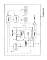
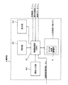
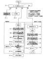
図1は、発明の実施の形態1に係る水素製造装置の構成を模式的に示すブロック図である。また、図2は、図1の改質部の構成を模式的に示す断面図である。また、図3は、図1の制御部の構成を模式的に示すブロック図であり、図4は、図1の制御部に格納されたプログラムの内容を概略的に示すフローチャートである。本実施の形態は、燃料電池発電システムに用いる水素製造装置を例示している。
(Embodiment 1)
FIG. 1 is a block diagram schematically showing the configuration of the hydrogen production apparatus according to
図1に示すように、水素製造装置100は、原料供給部6と、水供給部7と、水蒸発部8及び改質部2を備えた水素生成部1と、燃焼部4と、CO変成部10と、CO選択酸化部11と、制御部9とを主たる構成要素として備えている。
As shown in FIG. 1, a hydrogen production apparatus 100 includes a raw
原料供給部6は、原料流路aを介して水素生成部1の水蒸発部8に接続されるとともに、燃焼燃料流路fを介して燃焼部4に接続されている。水供給部7は、水流路bを介して水素生成部1の水蒸発部8に接続されている。また、水蒸発部8は、混合原料流路cを介して改質部2に接続されている。ここでは、燃焼部4における燃焼で生じる熱が、改質部2及び水蒸発部8の順で伝熱されるように、水素生成部1において改質部2が水蒸発部8よりも燃焼熱の伝熱経路の上流側に配置されている。改質部2は、改質ガス流路dを介してCO変成部10に接続されている。また、改質部2には、改質部2の温度を測定する改質温度測定部3が配設されている。CO変成部10は、変成後ガス流路eを介してCO選択酸化部11に接続されている。燃焼部4は、空気を供給するための燃焼ファン5を備えるとともに、燃焼に伴って生じる燃焼後ガスを排出するための燃焼後ガス流路gを有している。制御部9は、改質温度測定部3での検知温度が伝達されるように構成されるとともに、この検知温度に基づいて供給原料の組成を推定し、この推定結果に応じて水供給部7を制御して水供給量を制御する。また、制御部9は燃焼ファン5の回転数を制御し、それにより、燃焼部4への空気の供給量が調整される。
The raw
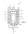
図2に示すように、改質部2は、円筒状の本体30から構成されている。なお、ここでは図示を省略しているが、改質部2は改質反応時に高温となるので、外部への放熱を防ぐために、本体30の外壁が断熱材によって覆われている。本体30の内部は、異なる径を有する複数の円筒体が同心的に配置されており、それにより、本体30の内部空間が、各円筒体によって半径方向に区画され、軸方向に延びる複数の環状の間隙31が形成されている。ここでは、本体30の内部を半径方向に区画する円筒体の周壁を縦壁32と呼ぶ。縦壁32の軸方向の所定端部には、縦壁32と同心的に配置された円板状又は中空円板状の横壁33が配置されている。
As shown in FIG. 2, the reforming
このような縦壁32及び横壁33によって形成された間隙31により、本体30の内部には半径方向の外周側から中心に向けて、二重構造の燃焼後ガス流路gの下流流路、改質ガス流路d、改質触媒層20、及び、二重構造の燃焼後ガス流路gの上流流路が形成される。
Due to the
本体軸方向に形成された燃焼後ガス流路gの下流流路と上流流路とは、本体30の底部で連通している。また、燃焼後ガス流路gの上流流路は、後述する燃焼部4の輻射筒40の上面及び側面に沿って形成されており、また、下流流路端部は、改質部2の外部に燃焼ガスを取り出し可能に形成されている。
The downstream flow path and the upstream flow path of the post-combustion gas flow path g formed in the main body axial direction communicate with each other at the bottom of the
改質触媒層20は、縦壁32及び横壁33によって形成された所定の間隙31に改質触媒を充填して形成されている。例えば、改質触媒として、ここではルテニウム触媒をアルミナ担体に担持して調製したものが用いられている。改質触媒層20は、燃焼後ガス流路gを介して後述する燃焼部4の輻射筒40の上面及び側面に沿って配置されている。改質触媒層20の上端は、混合原料流路cを介して水蒸発部8(図1)に連通し、下端は、改質ガス流路dに連通している。また、改質ガスの導入口となる改質ガス流路dの上流側端部には、改質温度測定部3が配設されている。ここでは、改質温度測定部3が温度検知手段として熱電対を備え、改質触媒層20を通流した気体の集合部分に熱電対が配置されている。なお、改質温度測定部3は、改質触媒層20の温度変化が比較的早く測定できる箇所及び雰囲気中であれば、配置位置はこれに限定されるものではない。
The reforming
改質部2の本体30の中心部には、輻射筒40が同心的に挿入されている。輻射筒40の上端は燃焼後ガス流路gに連通しており、輻射筒40の下端にはバーナ41が配設されている。この輻射筒40の内部空間が燃焼空間44となり火炎42が形成される。また、バーナ41を囲むように、燃焼ファン5(図1)から送られた空気の流路43が形成され、この空気の流路43が燃焼空間44に連通している。バーナ41は燃焼燃料流路fを介して原料供給部6(図1)に接続されている。このように、ここでは、輻射筒40、バーナ41、空気の流路43によって燃焼部4が構成され、燃焼ファン5たるシロッコファンによって空気が空気流路43に供給される。燃焼部4での燃焼によって改質部2が加熱され、ここでは、改質部2の温度が、原料として改質部2に供給されるメタン、エタン、プロパン等の炭化水素系原料のうちの85〜95%程度が水蒸気改質可能である温度、例えば700℃程度、となるように加熱量が制御されている。
A
原料供給部6(図1)は、炭化水素、ナフサ、アルコール等の少なくとも炭素及び水素から構成される有機化合物を含む原料を、原料流路aを介して水素生成部1に供給するとともに、燃焼燃料流路fを介してこの原料を燃焼部4に供給するように構成されている。ここでは、例えば、既存のインフラから供給される炭化水素系有機化合物を含む都市ガスやLPG等のガスを原料として利用するように構成されている。なお、図示を省略しているが、原料供給部6は、原料の供給圧力を増加させるブースタを備えるとともに、原料中の硫黄成分を低減する脱硫部を備え、脱硫部は、例えば原料中の付臭成分を除去するゼオライト吸着剤を備えている。
The raw material supply unit 6 (FIG. 1) supplies a raw material containing an organic compound composed of at least carbon and hydrogen such as hydrocarbon, naphtha, alcohol, etc. to the
水供給部7(図1)は、ここでは図示を省略しているが、イオン交換器及びプランジャーポンプを備えており、例えば、供給された水道水をイオン交換器で処理した後、プランジャーポンプで加圧して水素生成部1に供給する。
Although not shown here, the water supply unit 7 (FIG. 1) includes an ion exchanger and a plunger pump. For example, after the supplied tap water is processed by the ion exchanger, the plunger Pressurized with a pump and supplied to the
CO変成部10及びCO選択酸化部11は、改質部2で生成された改質ガスのCO濃度を低減するために配設されており、これらは、従来構造を有している。
The
図3に示すように、制御部9は、マイコン等のコンピュータによって構成されており、制御処理部(CPU)61と、データ収集蓄積部62’を有し半導体から構成された記憶部(内部メモリ)62と、操作入力部63と、表示部64と、時計部65とから構成されている。制御部9では、これらの各処理部61〜65によって、図4に示すプログラムが実行される。それにより、後述するように、基準データ作成モードでの運転時に、原料組成の推定時に判断基準となる基準データが作成され、また、通常運転モードでの運転時に、この基準データに基づいて原料組成の推定が行われかつ該推定組成に応じて水供給部7からの水供給量が調整される。
As shown in FIG. 3, the
以下、制御部9における図4のプログラムの実行プロセスに沿って、水素製造装置100の動作を説明する。 Hereinafter, the operation of the hydrogen production apparatus 100 will be described along the execution process of the program of FIG.
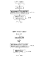
水素製造装置100の運転時には、まず、運転モードの選択が行われる(ステップS1)。水素製造装置100は4つの運転モード、すなわち、運転継続可能温度範囲設定モード、S/C設定モード、通常運転モード、及び、基準データ作成モードを有しており、モードの選択時には、ユーザが制御部9の操作入力部63に所望のモードを表示部64で確認しながら入力する。それにより、この入力情報が処理制御部61に伝達されてモード設定が行われる。
During operation of the hydrogen production apparatus 100, first, an operation mode is selected (step S1). The hydrogen production apparatus 100 has four operation modes, that is, an operation continuation possible temperature range setting mode, an S / C setting mode, a normal operation mode, and a reference data creation mode. A desired mode is input to the
運転継続可能温度範囲設定モードが選択されると、後述のように、通常運転モードでの運転において安定して良好な水素生成を行うことができる温度範囲の設定が行われる。設定の際には、ユーザが制御部9の操作入力部63に所望の温度範囲を表示部64で確認しながら入力する。それにより、この入力情報が処理制御部61に伝達されて運転継続可能温度範囲が設定される。ここでは、運転継続可能な温度範囲の下限値L1と上限値L2とが入力設定される(ステップS11)。
When the operation continuation possible temperature range setting mode is selected, as described later, a temperature range is set in which stable and satisfactory hydrogen generation can be performed in the operation in the normal operation mode. At the time of setting, the user inputs a desired temperature range to the
S/C設定モードが選択されると、改質部2に供給される原料及び水蒸気の混合ガス中における水分子と炭素原子との比(これをスチーム/カーボン比と呼びS/Cと呼ぶ)の設定が行われる(ステップS12)。後述するように、処理制御部61は、ここで設定されたS/C値と推定された原料組成とに基づいて改質部2への水の供給量を決定する。S/C設定時の入力方法は、運転継続可能温度範囲の入力方法と同様である。ここでは、S/Cが2.5〜3となる、すなわち、原料供給部6から改質部2へ供給される混合原料ガス中では、炭素原子1モルに対して水分子が2.5〜3モルとなるようにS/Cが設定され、ここでは、S/Cが3に設定されている。例えば、原料ガスとしてメタンが供給される場合にはメタン1モルに対する理論水量は2モルであるのに対してここでは3モルの水が供給され、エタンが供給される場合にはエタン1モルに対して理論水量が4モルであるのに対してここでは6モルの水が供給され、プロパンが供給される場合にはプロパン1モルに対して理論水量が6モルであるのに対してここでは9モルの水が供給される。なお、S/Cが3を上回る量の水が供給されると、改質部2では改質反応自体は速やかに進行するが、水の蒸発に余分なエネルギーを消費するため、水素生成時のエネルギー効率が低下する。一方、S/Cが2.5を下回ると、改質反応に十分な量の水が供給されず、原料ガスの熱分解による炭化あるいは改質ガスの不均化反応による炭素析出等が生じ、装置の圧損の増大や改質ガス流路の閉塞を引き起こす可能性がある。したがって、S/Cは2.5〜3の範囲が好ましい。
When the S / C setting mode is selected, the ratio of water molecules to carbon atoms in the mixed gas of the raw material and steam supplied to the reforming unit 2 (this is called the steam / carbon ratio and called S / C). Is set (step S12). As will be described later, the
原料組成を推定する時の基準となる基準データを作成する場合には、基準データ作成モードが選択されて運転が行われる(ステップS2〜6)。なお、基準データ作成モードでの運転、運転継続可能温度範囲の設定、及び、S/C設定を実施する順序は特には限定されないが、これらは、通常運転モードでの運転を実施する前に予め行われる。 When creating reference data that serves as a reference for estimating the raw material composition, the reference data creation mode is selected and operation is performed (steps S2 to S6). Note that the order in which the operation in the reference data creation mode, the setting of the temperature range where operation can be continued, and the S / C setting is not particularly limited is not particularly limited, but these are performed in advance before the operation in the normal operation mode is performed. Done.
通常の水素製造運転を行う場合には、通常運転モードが選択される。通常運転では、装置の運転開始から改質部2が所定温度となるまでの間(以下、これを起動時と呼ぶ)に改質部2を加熱する動作(以下、これを予熱動作と呼ぶ)と、前記所定温度(例えばこの場合は700℃程度)に達した改質部2で改質反応により水素ガスが生成される動作(以下、これを水素生成動作と呼ぶ)とが行われる。そして、この起動時の予熱動作の際に、基準データ作成モード運転で作成された基準データに基づいて原料組成の推定が行われるとともに、推定組成に応じて水供給量の調整が行われる(ステップS7〜10,13,14)。
When performing a normal hydrogen production operation, the normal operation mode is selected. In normal operation, an operation for heating the reforming
次に、基準データ作成モード及び通常運転モードでの運転について説明する。基準データ作成モードでの運転及び通常モードでの運転における原料ガス及び空気の供給量は、装置の大きさや規模等の条件によって適宜設定される。また、後述するように、改質部2の温度変化に基づいて原料の発熱量を算出することにより原料組成の推定が行われるので、推定精度を向上させるためには、燃焼による改質部2の温度変化を正確に把握する必要がある。それゆえ、正確な温度変化の把握のために、原料ガス及び空気の供給量を一定にして燃焼状態を安定化することが望ましい。
Next, the operation in the reference data creation mode and the normal operation mode will be described. The supply amounts of the source gas and air in the operation in the reference data creation mode and the operation in the normal mode are appropriately set according to conditions such as the size and scale of the apparatus. Further, as will be described later, since the raw material composition is estimated by calculating the calorific value of the raw material based on the temperature change of the reforming
まず、基準データ作成モードでの運転について説明する。基準データとは、原料供給部6から供給される原料の組成と、通常モードでの運転条件で装置を動作させてこの原料を燃焼部4で燃焼させた際の発熱量との相関関係を示すデータである。なお、ここでは、原料の組成とは、単位供給流量あたりの原料中に含まれる炭素数である。
First, the operation in the reference data creation mode will be described. The reference data indicates a correlation between the composition of the raw material supplied from the raw
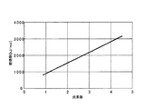
原料の組成とその発熱量との間には、以下のような相関関係が存在する。まず、図5は、化学工学便覧から抜粋した、アルカンにおける炭素数と燃焼熱との相関関係を示す図である。図5に示すように、基本的には、原料中の炭素数が増加すると、この原料の燃焼熱(発熱量)は増加し、燃焼熱(発熱量)と炭素数とはおおよそ比例関係にある。したがって、原料中の炭素数の増加に比例して燃焼による加熱量が増加し、よって、加熱対象である改質部2の温度上昇が促進される。水素製造装置100では、このような原料中の炭素数と発熱量との関係を利用することにより、予め作成した基準データに基づき、通常モード運転の予熱動作時の改質部2の温度変化から、原料中の炭素数を推定する。
The following correlation exists between the composition of the raw material and the calorific value thereof. First, FIG. 5 is a diagram showing the correlation between the number of carbons and the heat of combustion in alkanes extracted from the Chemical Engineering Handbook. As shown in FIG. 5, basically, when the number of carbons in the raw material increases, the combustion heat (heat generation amount) of the raw material increases, and the combustion heat (heat generation amount) and the number of carbons are approximately proportional. . Therefore, the amount of heating due to combustion increases in proportion to the increase in the number of carbons in the raw material, and thus the temperature rise of the reforming
基準データ作成時には、まず、操作入力部63を操作して基準データ作成モードを選択する。すると、基準データ作成モードに切り換わる(ステップS1)。そして、組成(具体的には、原料中の炭素数)が予め分かっている複数種類の原料ガス、例えば、メタン、エタン、プロパン等の炭素数の異なる複数の原料ガス、を用意し、その各々について、以下のようにして、燃焼部4での燃焼における発熱量を取得する。なお、基準データ作成モードでの運転は、通常モードの予熱動作での運転状態(具体的には、例えば燃焼部4の燃焼状態)と同様とする。
When creating the reference data, first, the
例えば、まず複数の原料ガスのうちの1種について、原料中の炭素数(メタンであれば1、エタンであれば2、プロパンであれば3)を制御部9の操作入力部63から処理制御部61に入力する(ステップS2)。そして、制御部9の処理制御部61から起動の制御信号が出力されて水素製造装置100が起動する。具体的には、図1及び図2に示すように、この原料ガスを、原料供給部6から燃焼燃料流路fを通じて燃焼部4のバーナ41に一定の供給流量で供給するとともに、供給された原料ガスの完全燃焼に必要な理論空気量の1.5倍の量の空気を燃焼ファン5から燃焼部4の空気流路43に供給する。そして、この原料ガスと空気とを反応させて燃焼空間44に火炎42を形成する。燃料部4での燃焼熱により、改質部2が加熱される。また、燃焼部4の燃焼空間44から燃焼後ガス流路gに導入されるとともに、この燃焼後ガス流路g中を改質部2の縦壁32及び横壁33に沿って流れる燃焼後ガスの保有熱によっても改質部2が加熱される。なお、この燃焼により、まず伝熱経路の上流側に位置する改質部2が加熱され、その後、下流側に位置する水蒸発部8が加熱される。
For example, first, for one of a plurality of source gases, the number of carbons in the source (1 for methane, 2 for ethane, 3 for propane) is controlled from the
このように燃焼部4での燃焼により加熱される改質部2では、改質温度測定部3によってその温度が常時検知されており、その検知温度は、制御部9の処理制御部61を経て記憶部62のデータ収集蓄積部62’に収集及び蓄積される。ここでは、燃焼により加熱された改質触媒層20を通流するガスの温度を、改質部2の温度としている。また、改質部2の検知温度とともに、時計部65により検知時刻が計測され、その計時信号が処理制御部61を介して記憶部62のデータ収集蓄積部62’に収集及び蓄積される(ステップS3)。
Thus, in the reforming
次に、データ収集蓄積部62’に蓄積された改質部2の検知温度データ及び計時信号をもとにして、演算処理により、原料ガスの単位供給流量あたりの発熱量を取得する。演算処理では、加熱(燃焼)開始から所定時間(例えばここでは5分)経過後までの期間における改質部2の検知温度の変化から、原料ガスの燃焼に伴う発熱量を算出するとともに、この期間に供給された原料ガスの総量を算出する。そして、得られた発熱量を原料ガスの総供給量で除算し、原料ガスの単位供給流量あたりの発熱量を算出する(ステップS4)。
Next, the calorific value per unit supply flow rate of the raw material gas is acquired by arithmetic processing based on the detected temperature data and the timing signal of the reforming
続いて、処理制御部61に入力された原料ガス中の炭素数と、上記のようにして得られた原料ガスの単位供給流量あたりの発熱量とが、記憶部62にデータとして記憶される(ステップS5)。
Subsequently, the number of carbons in the raw material gas input to the
処理制御部61から終了の制御信号が出力されるまで、炭素数の異なる複数の原料ガスの各々について上記のステップS2〜S5のプロセスがそれぞれ行われる。それにより、炭素数の異なる原料ガスの各々について、原料ガス中の炭素数とその単位供給流量あたりの発熱量とがデータとして記憶部62に記憶される。そして、終了の制御信号が出力されると、記憶部62に記憶された上記個々のデータに基づいて、原料ガス中の炭素数とその原料ガスの燃焼における単位供給流量あたりの発熱量との相関関係のデータ、すなわち基準データ、が作成される(ステップS6)。
Until the end control signal is output from the
このようにして作成された基準データは、前述のように、通常モードの運転状態と同様の運転状態で装置を動作させて作成したものであるので、作成された基準データには、装置の構成上の固有の特性や使用状態における固有の特性等が反映されている。具体的には、改質温度測定部3で検知される改質部2の温度の変化は、水素製造装置100の構成、容積、熱容量等や、燃焼部4での燃焼状態等の影響を受けることから、装置構成や使用状態等の特性が反映された基準データを作成してこれを通常モード運転での原料組成の推定に利用することより、正確な原料組成の推定が可能となる。
Since the reference data created in this way is created by operating the device in the same operation state as the normal mode operation state as described above, the created reference data includes the configuration of the device. The above unique characteristics and the unique characteristics in use state are reflected. Specifically, the change in the temperature of the reforming
次に、上記の基準データを利用して装置の起動時の予熱動作において原料組成の推定及び水供給量の調整が行われる通常運転モードでの運転について説明する。 Next, the operation in the normal operation mode in which the raw material composition is estimated and the water supply amount is adjusted in the preheating operation at the start-up of the apparatus using the reference data will be described.
まず、操作入力部63を操作して通常運転モードを選択する。すると、通常運転モードに切り換わる(ステップS1)。そして、処理制御部61から起動の制御信号が出力されて装置が起動する。具体的には、原料供給部6から燃焼燃料流路fを介して燃焼部4のバーナ41に原料を所定の供給流量で供給するとともに、所定の供給流量で燃焼ファン5から燃焼部4の燃焼空間44に空気を供給する。例えば、ここでは、メタンを含むこと以外は組成が明らかでない原料ガスを用いており、この場合の空気供給量は、メタンの完全燃焼に必要な理論空気量の1.5倍としている。そして、この原料ガスと空気とを反応させて燃焼空間44に火炎42を形成し、前述のように燃焼熱及び燃焼後ガスの熱によって改質部2を加熱する。加熱時、改質部2の温度は改質温度測定部3によって常時検知され、検知温度は、制御部9の処理制御部61を介して記憶部62のデータ収集蓄積部62’に収集及び蓄積される。また、この温度検知とともに、時計部65により検知時刻が計測されその計時信号が処理制御部61を介して記憶部62のデータ収集蓄積部62’に収集及び蓄積される(ステップS7)。
First, the
データ収集蓄積部62’に蓄積された改質部2の検知温度データ及び計時信号をもとにして、演算処理により、原料ガスの単位供給流量あたりの発熱量を取得する。ここでの演算処理は、基準データ作成時の演算処理と同様である。(ステップS8)。
The calorific value per unit supply flow rate of the raw material gas is acquired by arithmetic processing based on the detected temperature data of the reforming
続いて、処理制御部61によって、この算出された単位供給流量あたりの発熱量と、記憶部62に記憶された前述の基準データとの比較が行われる(ステップS9)。そして、比較結果から、原料ガスの組成、具体的には原料ガス中の炭素数を推定する(ステップS10)。ここでは、ステップS9及びステップS10のプロセスを原料組成の推定プロセスと呼び、その詳細については後述する。続いて、水素製造装置100において安定して良好な運転を行うために、改質部2の温度から、装置の運転の継続が可能であるが否かの判定が行われる。後述の図6で詳細を説明するが、装置の運転継続が可能であるか否かは、加熱から5分経過後の改質部2の温度が、前述のステップS11で設定した運転継続可能温度範囲L1〜L2に入るか否かで判定する(ステップS13)。そして、この範囲から外れる場合には、処理制御部61から停止の制御信号が出力されて装置の運転が停止され、温度範囲内である場合には、以下のプロセスが引き続き行われる。
Subsequently, the
上記のようにして得られた原料組成推定情報と、前述のステップS12で設定したS/C値(すなわち、改質部2に供給される混合原料ガス中の水分子Sと炭素原子Cとの比)とに基づいて、処理制御部61が、推定された原料組成に応じた適切な水の供給量を算出する。そして、算出された水の供給量に基づいて水供給部7を制御し、水素生成部1への水供給量を調整する(ステップS14)。
The raw material composition estimation information obtained as described above and the S / C value set in step S12 described above (that is, the water molecules S and the carbon atoms C in the mixed raw material gas supplied to the reforming unit 2). Based on the ratio, the
このようにして、通常運転モードでの運転では、起動時の予熱動作の際に原料組成の推定及び水供給量の調整が行われる。そして、予熱動作の後、水素製造装置100では、従来の水素生成動作が行われて水素ガスの製造が行われる。すなわち、燃焼部4での燃焼により加熱されて改質部2が所定の温度に達すると、燃焼部4に原料ガスが供給されるだけでなく、原料供給部6から原料供給流路aを通じて原料ガスが水素生成部1にも供給されるとともに、水供給部7から水供給流路bを通じて、前記供給量に調整された水が水素生成部1に供給される。水素生成部1に供給された原料ガス及び水は、水蒸発部8に導入される。水蒸発部8では、水が蒸発して水蒸気となり、原料ガスと混合されて混合原料ガスが生成される。
Thus, in the operation in the normal operation mode, the estimation of the raw material composition and the adjustment of the water supply amount are performed during the preheating operation at the time of startup. Then, after the preheating operation, the hydrogen production apparatus 100 performs a conventional hydrogen generation operation to produce hydrogen gas. That is, when heated by the combustion in the
図2に示すように、混合原料ガスは、混合原料流路cを通じて改質部2の改質触媒層20へ供給され、改質触媒層20を縦壁32に沿って軸方向下向きに流れる。この改質触媒層20を通流する過程において、原料ガスが水蒸気改質されて改質ガスが生成する。生成された改質ガスは、改質触媒層20の下端から改質ガス流路dに導入される。改質ガスは、改質ガス流路dを縦壁32に沿って軸方向上向きに流れて改質部2の外部に取り出されCO変成部10に到達し、ここでCO低減処理が行われてCO変成後ガスが生成される。さらに、CO変成後ガスは、変成後ガス流路eを通じてCO選択酸化部11に送られてCO低減処理される。このようにして得られたCO濃度が低減された水素ガスは、ここでは、後述の実施の形態6において説明するように、燃料電池発電システムの燃料電池101に、発電燃料として供給される。
As shown in FIG. 2, the mixed raw material gas is supplied to the reforming
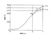
続いて、原料ガス組成の推定プロセスの詳細について説明する。図6は、組成の異なる原料ガスA〜Dの各々が燃焼部4に供給された場合における改質温度測定部3の経時的な温度変化を示す図である。ここで、原料ガスAは10vol%の窒素を含むメタンであり、原料ガスBは100vol%のメタンであり、原料ガスCは20vol%のエタンを含むメタンであり、原料ガスDは50vol%のエタンを含むメタンである。原料ガスA、原料ガスB、原料ガスC及び原料ガスDについて単位供給流量あたりのガス中の炭素数を比較すると、原料ガスDが最も多く、原料ガスC、原料ガスB、及び原料ガスAの順に炭素数が減少する。ここで、図5において前述したように、原料ガス中の炭素数に比例して原料ガスの燃焼熱が増加することから、原料組成の異なる原料ガスA〜Dでは、供給した原料ガスの単位供給流量あたりの発熱量は、原料ガスAが最も少なく、原料ガスB、原料ガスC、原料ガスDの順に増加し、よって、所定の加熱時間経過後(ここでは5分経過後)に改質温度測定部3で検知される改質部2の温度は、原料ガスAの場合が最も低く、原料ガスB、原料ガスC、原料ガスDの順に高くなる。
Then, the detail of the estimation process of raw material gas composition is demonstrated. FIG. 6 is a diagram illustrating a change in temperature over time of the reforming
原料組成が不明な状態で原料ガスA〜Dが供給されると、前述のように、制御部9の処理制御部61では、原料ガスの単位供給流量あたりの発熱量と基準データとの比較が行われ、比較結果に基づいて、原料ガス中の炭素数が推定される(図4のステップS9及びステップS10)。ここでは、この比較と推定のプロセスを、5分加熱後の改質部2の検知温度TA〜TDと、基準データより得られる基準点P1〜P3とを用いて説明する。この基準点P1〜P3は、制御部9の記憶部62に記憶された基準データの一部のデータを図示したものであり、具体的には、単位供給流量あたりの炭素数が1である原料ガス、該炭素数が1.1である原料ガス、及び、該炭素数が1.2である原料ガスの各々について、該原料ガスを完全に燃焼させて改質部2を加熱した場合の、加熱開始から5分経過後の検知温度を示している。なお、原料組成推定プロセスでは、実際には、5分間の加熱における改質部2の温度変化から算出された発熱量をに基づいて推定が行われるが、発熱量は改質部2の温度変化に直接的に反映されることから、ここでは、図6を用いた説明上、5分加熱後の改質部2の検知温度に基づいて推定を行っている。
When the raw material gases A to D are supplied in a state in which the raw material composition is unknown, as described above, the
例えば、原料ガスAが供給された場合、5分加熱後の温度TAは、基準点P1よりも低くなっている。ここで、基準点P1よりも温度が低いとは、原料ガスAの方が、炭素数が1の原料ガスよりも、単位供給流量あたりの発熱量が少ないことを示しており、よって、発熱量と炭素数との関係から、原料ガスAは、単位供給流量あたりの炭素数が1よりも少ないと推定される。また、原料ガスBでは、5分加熱後の温度TBが、基準点P1と基準点P2との間となっており、よって、原料ガスBの単位供給流量あたりの発熱量は、炭素数が1の原料ガスよりも大きくかつ炭素数が1.1の原料ガスよりも小さいことが示される。このことから、原料ガスBは、単位供給流量あたりの炭素数が1より多く1.1より少ないと推定される。また、原料ガスCでは、5分加熱後の温度TCが、基準点P2と基準点P3との間となっており、よって、原料ガスCの単位供給流量あたりの発熱量は、炭素数が1.1の原料ガスよりも大きくかつ炭素数が1.2の原料ガスよりも小さいことが示される。よって、原料ガスCは、単位供給流量あたりの炭素数が1.1より多く1.2より少ないと推定される。また、原料ガスDでは、5分加熱後の温度TDが、基準点P3より高くなっており、よって、炭素数が1.2の原料ガスよりも発熱量が大きいことが示される。したがって、原料ガスDは、単位供給流量あたりの炭素数が1.2より多いと推定される。 For example, when the raw material gas A is supplied, the temperature TA after heating for 5 minutes is lower than the reference point P1. Here, that the temperature is lower than the reference point P1 indicates that the raw material gas A has a lower calorific value per unit supply flow rate than the raw material gas having 1 carbon number, and thus the calorific value. From the relationship between the number of carbon atoms and the number of carbon atoms, it is estimated that the raw material gas A has a carbon number per unit supply flow rate of less than 1. Further, in the raw material gas B, the temperature TB after heating for 5 minutes is between the reference point P1 and the reference point P2, and therefore the calorific value per unit supply flow rate of the raw material gas B is 1 carbon number. It is shown that it is larger than the raw material gas and smaller than the raw material gas having 1.1 carbon atoms. From this, it is estimated that the source gas B has a carbon number per unit supply flow rate of more than 1 and less than 1.1. Further, in the raw material gas C, the temperature TC after heating for 5 minutes is between the reference point P2 and the reference point P3. Therefore, the calorific value per unit supply flow rate of the raw material gas C is 1 carbon number. It is shown that it is larger than the raw material gas of .1 and smaller than the raw material gas having 1.2 carbon atoms. Therefore, it is estimated that the raw material gas C has a carbon number per unit supply flow rate of more than 1.1 and less than 1.2. In addition, in the raw material gas D, the temperature TD after heating for 5 minutes is higher than the reference point P3, and thus it is shown that the calorific value is larger than that of the raw material gas having 1.2 carbon atoms. Therefore, it is estimated that the raw material gas D has more than 1.2 carbon atoms per unit supply flow rate.
ところで、上記のプロセスにより原料ガスの組成を推定して水の供給量を適正化すれば、理論的には、原料ガスと水とを適切な割合で改質部2に供給して適切な状態で改質反応を行うことが可能となる。しかしながら、実際には、例えば原料ガスAのように炭素数が少ない原料ガスが供給された場合、原料ガス供給流量に対して適正な量の改質ガスを生成することが困難となり、また、原料ガス中の不活性成分により熱損失が生じて効率的な水素生成動作を行うことが困難となるおそれがある。また、原料ガスDのように炭素数が多い原料ガスが供給された場合、水供給量の適正な制御が困難となり、また、高い燃焼負荷となるため燃焼部4において適正な燃焼を継続することが困難となる等、装置上の制約が生じるおそれがある。それゆえ、これらの場合には、原料組成を推定して適切な量の水を供給することができても、適切に水素ガスを生成することが困難となる。そこで、安定して良好な水素生成を実現するために、例えば、安定して良好な水素生成が可能である原料ガスを選択するべく、装置の運転継続が可能である温度範囲(以下、これを運転継続可能範囲と呼ぶ)を定める。そして、この運転継続可能範囲内から外れる場合には、装置の運転を停止する。
By the way, if the composition of the raw material gas is estimated by the above process and the supply amount of water is optimized, the raw material gas and water are theoretically supplied to the reforming
ここでは、前述のステップS11(図4)において、5分加熱後の改質部2の温度に運転継続可能範囲の下限値L1と上限値L2とを予め設定し、通常運転モードでの運転における5分加熱後の改質部2の検知温度が運転継続可能範囲L1〜L2内であるか否かを処理制御部61が判定する(ステップS13)。改質部2の検知温度が下限値L1よりも低い場合及び上限値L2よりも高い場合には、処理制御部61から停止の制御信号が出力されて装置の運転が停止する。一方、運転継続可能範囲L1〜L2内である場合には、運転が継続されて上記のステップS14のプロセスが行われる。具体的に、ここでは、下限値L1が300℃に設定され、上限値L2が400℃に設定されている。したがって、5分加熱後の改質部2の検知温度が300℃よりも低い場合、及び、400℃よりも高い場合には装置が停止し、一方、300〜400℃の範囲内である場合には、運転が継続される。
Here, in the above-described step S11 (FIG. 4), the lower limit value L1 and the upper limit value L2 of the operable continuation range are set in advance to the temperature of the reforming
このように運転継続可能範囲が設定されているため、例えば、原料ガスAが供給された場合、5分加熱後の改質部2の温度TAは下限の温度L1よりも低くなるため、運転が停止する。また、原料ガスDが供給された場合には、5分加熱後の改質部2の温度TDは上限の温度L2よりも高くなるため、運転が停止する。一方、原料ガスB及び原料ガスCが供給された場合には、5分加熱後の改質部2の温度TB、TCが運転継続可能範囲L1〜L2内であるため、これらの場合には運転が継続され、炭素数の推定が行われるとともにこの推定に応じて水の供給量が調整される。そして、原料ガスB又は原料ガスCと水とを用いて適切な状態の下、効率よく改質反応が行われ、それにより、安定して良好な水素生成が可能となる。
Since the operation continuation possible range is set in this way, for example, when the raw material gas A is supplied, the temperature TA of the reforming
以上のように、本実施の形態の水素製造装置100によれば、供給される原料ガスの組成に応じて水の供給量を調整することができるため、改質触媒層20の触媒の劣化や流路の閉塞等の問題を生じることなく効率よく安定して水素を生成することが可能となる。したがって、このような水素製造装置は、経済性及びエネルギー効率に優れるとともに、高い汎用性が実現される。 As described above, according to the hydrogen production apparatus 100 of the present embodiment, the amount of water supplied can be adjusted according to the composition of the supplied raw material gas. Hydrogen can be generated efficiently and stably without causing problems such as blockage of the flow path. Therefore, such a hydrogen production apparatus is excellent in economic efficiency and energy efficiency, and high versatility is realized.
また、本実施の形態では、原料ガスの単位供給流量あたりの発熱量と原料ガスの組成とが原料ガスの組成推定プロセスにおいて得られるので、この得られた原料組成及び発熱量から燃焼部4での燃焼状態の最適化を図ることも可能となる。そして、燃焼状態の最適化が図られることにより、水素生成動作において、改質部2における改質反応の効率が向上する。
Further, in the present embodiment, since the calorific value per unit supply flow rate of the raw material gas and the composition of the raw material gas are obtained in the raw material gas composition estimation process, the
水素製造装置100では、供給される原料ガスの組成が変化しない場合には、初めに調整した供給量で水を供給すればよいが、原料ガスの組成が変化する場合には、改めて原料組成の推定及び水供給量の調整を行う。それにより、原料ガスの組成が変化しても、効率よく安定して水素ガスを製造することが可能となる。なお、原料組成の変化の有無に関わらず、定期的に原料組成の推定及び水供給量の調整を行ってもよい。 In the hydrogen production apparatus 100, when the composition of the supplied raw material gas does not change, water may be supplied at the initially adjusted supply amount. However, when the raw material gas composition changes, the raw material composition is changed. Estimate and adjust water supply. Thereby, even if the composition of the raw material gas changes, it becomes possible to produce hydrogen gas efficiently and stably. Regardless of whether the raw material composition has changed or not, the raw material composition may be estimated and the water supply amount adjusted periodically.
(実施の形態2)
本発明の実施の形態2に係る水素製造装置100は、実施の形態1の装置と同様の構成を有するが、原料組成の推定プロセスが実施の形態1と相違点を有する。実施の形態1では、例えば、都市ガスからLPGに原料ガスを変更する等して大幅に原料ガスの組成が変化する場合に、後述する理由から、正確な原料組成の推定が困難となることある。このため、本実施の形態では、この点を解消してより正確な推定を行うことができるように、原料組成の推定プロセスにおいて、燃焼部4への空気供給量を変化させた後に原料組成の推定を行う。以下においては、本実施の形態と実施の形態1との推定プロセスの相違点について説明し、それ以外は実施の形態1と同様とする。
(Embodiment 2)
The hydrogen production apparatus 100 according to
ここでは、具体的に、20vol%のエタンを含むメタンである原料ガスCと、50vol%のプロパンを含むメタンである原料ガスEとがそれぞれ水素製造装置100に供給された場合を例に挙げて説明する。 Here, specifically, as an example, a raw material gas C, which is methane containing 20 vol% ethane, and a raw material gas E, which is methane containing 50 vol% propane, are supplied to the hydrogen production apparatus 100, respectively. explain.
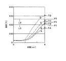
図7は、原料ガスC及び原料ガスEが供給された各場合における改質部2の経時的な温度変化を示す図である。加熱開始から5分経過時点迄の間は、実施の形態1と同様の所定の供給流量で原料ガスC又は原料ガスEと空気とが燃焼部4に供給されて燃焼が行われ、それにより、図7に示すように、原料ガスCを供給した場合と原料ガスEを供給した場合とで、改質部2の温度変化がほぼ同一の推移を示す。
FIG. 7 is a diagram illustrating a change in temperature over time of the reforming
ここで、このように原料ガスCと原料ガスEとは組成(具体的には炭素数)が異なるにもかかわらず同様の温度変化を示すことから、実施の形態1のプロセスに従いこの5分間における温度変化に基づいて発熱量を算出して原料組成の推定を行うと、原料ガスCと原料ガスEとで推定結果が同一となり、両者を区別することができない。このように実際の組成と推定結果との間にずれが生じるのは、以下の理由による。 Here, since the raw material gas C and the raw material gas E show the same temperature change even though the compositions (specifically, the number of carbon atoms) are different from each other, according to the process of the first embodiment, in this 5 minutes. If the calorific value is calculated based on the temperature change and the raw material composition is estimated, the estimation results are the same for the raw material gas C and the raw material gas E, and the two cannot be distinguished. The difference between the actual composition and the estimation result is caused by the following reason.
50vol%のプロパンを含むメタンである原料ガスEは、20vol%のエタンを含むメタンである原料ガスCよりも単位供給流量当たりの炭素数が多く、よって、十分な空気が燃焼部4に供給されて十分に燃焼が行われた場合には、燃焼に伴う発熱量が、原料ガスCの発熱量よりも多くなる。しかしながら、ここでは、実施の形態1において前述したように、燃焼部4に供給される空気の供給量がメタンを基準にして設定されているため、原料ガスC及び原料ガスE中の燃焼成分(具体的にはメタン成分、エタン成分、プロパン成分)を燃焼させるのに十分な量の空気が供給されているとは限らず、特に、炭素数が多い原料ガスEでは、このような空気供給量では十分な燃焼が行われない。そして、十分な量の空気が供給されない原料ガスEの燃焼では、未燃のガス成分が増加し、結果として、燃焼後のガス温度が下がってしまう。それゆえ、原料ガスEと原料ガスCとでは、組成の異なる原料ガスであるにもかかわらず、改質部2の温度変化が一致する。そして、原料ガスEの原料組成を原料ガスCの組成と同一、すなわち、原料ガスEは20vol%のエタンを含むメタンであると推定しこの推定に基づいて水供給量の調整が行われると、推定された組成と実際の組成との間に誤差(以下、推定誤差と呼ぶ)が生じるため、適切な供給量で水を供給することができない。
The raw material gas E, which is methane containing 50 vol% propane, has a larger number of carbons per unit supply flow rate than the raw material gas C, which is methane containing 20 vol% ethane, so that sufficient air is supplied to the
そこで、本実施の形態では、このような空気供給量不足による推定誤差の発生を防止するため、加熱開始から5分経過後に、燃焼部4への空気の供給量を増加させ、該増加後の改質部2の温度変化を調べる。そして、空気供給量の調整後、原料組成の推定を行う。ここでは、5分加熱後に空気供給流量を調整し、メタンの完全燃焼に必要な理論空気量の2.5倍で空気を供給して引き続き燃焼を行う。そして、それから2分経過後(すなわち、加熱開始から7分経過後)に、原料組成推定を行う。7分経過時点における原料組成推定のプロセスは、実施の形態1の図4のステップS7〜S14のプロセスと同様であるが、ここでは、空気供給量を増加させた後の原料ガスの単位流量あたりの発熱量を算出するとともに、この2分間における発熱量を用いて推定が行われる。すなわち、ステップS7及びステップS8において、7分加熱後の改質部2の温度T’E,T’Cを検知し、この2分間における温度変化(T’E−TC,T’C−TC)から原料ガスE及び原料ガスCの発熱量を算出するとともに、算出された発熱量をこの間の原料ガスの総供給量で除算して、空気供給量調整後の原料ガスの単位供給流量あたりの発熱量を求める。そして、実施の形態1と同様、ステップS9〜10,13,14のプロセスに従って、原料組成の推定及び水供給量の調整を行う。なお、7分加熱後の改質部2の温度は、5分加熱後の温度よりも高くなることから、本実施の形態では、ステップS11の運転継続可能温度範囲設定プロセスにおいて、運転継続が可能である改質部2の温度範囲L3〜L4の下限の温度L3を470℃に設定し、上限の温度L4を530℃設定している。
Therefore, in the present embodiment, in order to prevent the occurrence of such an estimation error due to the shortage of the air supply amount, the air supply amount to the
このような本実施の形態の原料組成推定プロセスでは、十分な量の空気が供給されて原料ガスEの燃焼成分が十分に燃焼されるので、原料ガスCよりも炭素数が多い原料Eでは、炭素数を反映して燃焼時の発熱量が原料ガスCよりも多くなり、よって、改質部2の温度上昇の割合が原料ガスCよりも大きくなる。したがって、組成の異なる原料ガスC及び原料ガスEについて、原料組成の推定を正確に行うことができ、実施の形態1で前述した効果がより有効に奏される。
In such a raw material composition estimation process of the present embodiment, since a sufficient amount of air is supplied and the combustion component of the raw material gas E is sufficiently combusted, in the raw material E having more carbon atoms than the raw material gas C, Reflecting the number of carbons, the calorific value at the time of combustion is larger than that of the raw material gas C, and therefore the rate of temperature rise in the reforming
ところで、原料組成の変化幅が予め決まっておりその幅が小さい場合には、実施の形態1のプロセスにより原料の組成推定を行っても生じる推定誤差が少ないが、本実施の形態のプロセスによれば、推定誤差の発生をさらに抑制することが可能となる。また、空気供給量を調整する回数は特に限定されるものではなく、このような調整を繰り返し行うことで、原料組成の推定精度をより向上させることが可能となる。 By the way, when the change width of the raw material composition is determined in advance and the width is small, there is little estimation error generated even if the raw material composition is estimated by the process of the first embodiment. Thus, it is possible to further suppress the occurrence of estimation errors. In addition, the number of times of adjusting the air supply amount is not particularly limited, and it is possible to further improve the estimation accuracy of the raw material composition by repeatedly performing such adjustment.
(実施の形態3)
本発明の実施の形態3に係る水素製造装置100は、実施の形態1の装置と同様の構成を有するものである。また、本実施の形態における原料組成の推定プロセスでは、実施の形態2のプロセスと同様、原料ガスの組成が大きく変化した場合においても正確な推定を行えるよう、原料ガス中の燃焼成分の十分な燃焼を行った上で推定が行われるものであるが、実施の形態2のように空気の供給量を調整するのではなく、原料の供給量を調整することにより十分な燃焼を実現する点が、実施の形態2と異なる。
(Embodiment 3)
A hydrogen production apparatus 100 according to
すなわち、実施の形態2では、5分加熱後に空気供給量を増加させることにより原料ガスE及び原料ガスCの十分な燃焼を実現し、空気供給量調整後の発熱量の違いから原料ガスEと原料ガスCとを区別しているが、本実施の形態では、空気の供給量は一定に保持したままで原料ガスE及び原料ガスCの供給量を調整して減少させて相対比を変化させることにより、原料ガスE及び原料ガスCにおいて十分な燃焼を実現し、原料ガス供給量調整後の両者の発熱量の違いから両者を区別している。 That is, in the second embodiment, sufficient combustion of the raw material gas E and the raw material gas C is realized by increasing the air supply amount after heating for 5 minutes, and due to the difference in calorific value after adjusting the air supply amount, Although it is distinguished from the source gas C, in this embodiment, the supply rate of the source gas E and the source gas C is adjusted and decreased while changing the relative ratio while keeping the supply rate of air constant. Thus, sufficient combustion is realized in the raw material gas E and the raw material gas C, and the two are distinguished from the difference in calorific value between the two after the raw material gas supply amount adjustment.
例えば、原料ガスE及び原料ガスCの各々の燃焼時において、5分加熱後から7分加熱後に到るまでの間、原料ガスの供給流量を、加熱開始から5分経過迄の間の供給量よりも少なくする。この時、空気の供給量は、加熱開始から7分経過迄の間、一定に保持する。このように原料ガスの供給量を減少させることにより、5分加熱後から7分加熱後に到るまでの間では、供給空気に対する供給原料ガスの割合が、初めの5分間よりも小さくなる。このため、空気の供給量は一定であっても、原料ガスの供給量を減少させた期間では、原料ガスの十分な燃焼を実現することができる。そして、このように十分な燃焼が実現されることにより、原料ガスの供給量を減少させた期間では、原料ガスEと原料ガスCとで、燃焼時の発熱量に違いが生じる。よって、実施の形態2において前述したプロセスと同様のプロセスにより、原料ガスE及び原料ガスCの組成を正確に推定できる。 For example, at the time of combustion of each of the raw material gas E and the raw material gas C, the supply flow rate of the raw material gas from the start of heating to the passage of 5 minutes from the start of heating for 5 minutes until the end of heating for 7 minutes. Less than. At this time, the air supply amount is kept constant from the start of heating until the elapse of 7 minutes. By reducing the supply amount of the raw material gas in this way, the ratio of the raw material gas to the supply air becomes smaller than the first five minutes from the time after heating for 5 minutes until the time after heating for 7 minutes. For this reason, even if the supply amount of air is constant, sufficient combustion of the source gas can be realized in the period when the supply amount of the source gas is reduced. And by realizing sufficient combustion in this way, in the period when the supply amount of the raw material gas is decreased, the raw material gas E and the raw material gas C are different in the calorific value at the time of combustion. Therefore, the composition of the raw material gas E and the raw material gas C can be accurately estimated by a process similar to the process described in the second embodiment.
(実施の形態4)
図8は、本発明の実施の形態4に係る水素製造装置の構成を示す模式図である。図8に示すように、本実施の形態の水素製造装置100は、実施の形態1の水素製造装置100と同様の構成を有するが、装置の周囲温度を測定する環境温度検知部50が設けられた点が実施の形態1とは異なっている。以下においては、本実施の形態と実施の形態1との相違点について説明し、それ以外は実施の形態1と同様とする。
(Embodiment 4)
FIG. 8 is a schematic diagram showing a configuration of a hydrogen production apparatus according to
水素製造装置100の予熱動作では、改質温度測定部3で検知される改質部2の温度が、装置が設置されている環境の温度状態(以下、環境温度と呼ぶ)の影響を受ける。ここで、実施の形態1で前述したように、原料組成を正確に推定するためには、原料ガスの燃焼に伴う改質部2の温度変化を正確に把握する必要があり、よって、燃焼以外の要因による改質部2の温度変化を除いた実質的な温度変化に基づいて原料組成の推定を行うことが望ましい。そこで、本実施の形態では、燃焼による実質的な改質部2の温度変化を正確に把握するために、基準データ作成時及び原料組成推定プロセスにおいて、水素製造装置100が設置されている環境温度を環境温度測定部50によって検知する。環境温度測定部50は、例えば、熱電対等の温度検知手段を備えている。なお、環境温度測定部50の配置位置は、装置外部の環境温度を検知できる位置であれば、特に限定されるものではない。
In the preheating operation of the hydrogen production apparatus 100, the temperature of the reforming
図9は、本実施の形態の制御部9に格納されたプログラムの内容を概略的に示すフローチャートである。なお、図9では、実施の形態1と異なるプロセスのみを示しており、それ以外は、実施の形態1のプロセス(図4参照)と同様である。
FIG. 9 is a flowchart schematically showing the contents of the program stored in the
図9に示すように、本実施の形態では、基準データ作成モード運転と通常運転モードでの運転における原料組成推定プロセスとにおいて、改質温度測定部3により改質部2の温度が検知されるとともに、水素製造装置100の外部の環境温度が環境温度測定部50によって常時検知される。そして、両検知温度が、計時信号とともに制御部9の記憶部62のデータ収集蓄積部62’に収集及び蓄積される(ステップS3A及びステップS7A)。そして、データ収集蓄積部62’に収集された環境温度データと改質部2の温度データとが処理制御部61によって演算処理され、それにより、検知された改質部2の温度変化から環境温度の変化の影響を除いた、原料ガスの燃焼による実質的な改質部2の温度変化が求められる(ステップS3B及びステップS7B)。基準データ作成モードでの運転では、このようにして得られた実質的な改質部2の温度変化から発熱量が算出されて基準データが作成される。また、通常運転モードでの運転では、原料組成推定プロセスにおいて、この実質的な改質部2の温度変化から算出された発熱量を用いて、原料組成の推定が行われる。
As shown in FIG. 9, in the present embodiment, the temperature of the reforming
以上のように、本実施の形態の水素製造装置100によれば、装置周囲の環境温度を考慮した実質的な改質部2の温度変化から燃焼に伴う実質的な発熱量を求めるとともに該発熱量に基づいて原料組成の推定を行うため、推定精度の向上が図られる。したがって、この水素製造装置100では、より正確な原料組成の推定を行うことが可能となる。
As described above, according to the hydrogen production apparatus 100 of the present embodiment, the substantial heat generation amount accompanying combustion is obtained from the substantial temperature change of the reforming
なお、上記においては、実施の形態1と同様の原料組成推定プロセスが行われる場合について説明したが、実施の形態2及び実施の形態3と同様のプロセスにより、原料組成の推定が行われてもよい。 In the above description, the case where the raw material composition estimation process similar to that of the first embodiment is performed has been described. However, even if the raw material composition is estimated by the same process as that of the second and third embodiments. Good.
(実施の形態5)
図10は、本発明の実施の形態5に係る水素製造装置の構成を示す模式図である。図10に示すように、本実施の形態の水素製造装置100は、実施の形態1の装置と同様の構成を有するが、燃焼部4の温度を検知する燃焼温度測定部51が設けられた点が、実施の形態1とは異なっている。そして、本実施の形態では、この燃焼温度測定部51で検知された燃焼部4の温度から原料ガスの燃焼時の発熱量を算出し、基準データの作成及び原料組成の推定が行われる。以下、本実施の形態と実施の形態1との相違点について説明するが、それ以外については実施の形態1と同様である。なお、本実施の形態では、実施の形態1と同様に改質温度測定部3が設けられているが、これは水素生成動作時の改質部2の温度を検知するためのものであり、基準データの作成及び原料組成の推定には関与していない。
(Embodiment 5)
FIG. 10 is a schematic diagram showing a configuration of a hydrogen production apparatus according to
燃焼温度測定部51は、温度検知手段として例えば熱電対を備えている。熱電対の配設位置は、燃焼に伴う燃焼部4の温度変化を検知できるのであれば、特には限定されない。ここでは、火炎42の外炎の温度を検知可能に配置されているが、例えば、燃焼空間44を構成する構成部材(具体的には、輻射筒40の内壁等)の温度を検知するように配置されてもよく、また、燃焼後ガス流路gを流れる燃焼後ガスの温度を検知するように配置されてもよい。
The combustion
本実施の形態の基準データ作成プロセス及び原料組成推定プロセスは、実施の形態1において前述したプロセスと同様であるが、実施の形態1では改質温度測定部3で検知した改質部2の温度を用いて該温度の変化から原料ガスの発熱量を算出するのに対して、本実施の形態では、燃焼温度測定部51で検知した燃焼部4の温度を用いて該温度の変化から原料ガスの発熱量を算出する。かかる構成の本実施の形態では、以下の効果が奏される。
The reference data creation process and raw material composition estimation process of the present embodiment are the same as those described in the first embodiment, but in the first embodiment, the temperature of the reforming
図11は、原料組成の異なる原料ガスA〜Dを供給して燃焼させた場合の燃焼部4の経時的な温度変化を示す図である。実施の形態1の図6の場合と同様、原料ガスAは10vol%の窒素を含むメタンであり、原料ガスBは100vol%のメタンであり、原料ガスCは20vol%のエタンを含むメタンであり、原料ガスDは50vol%のエタンを含むメタンである。
FIG. 11 is a diagram illustrating a temperature change with time of the
前述のように、原料ガスA〜Dでは、炭素数が原料ガスA、原料ガスB、原料ガスC、原料ガスDの順に多くなっており、このため、燃焼時の発熱量は、原料ガスA、原料ガスB、原料ガスC、及び原料ガスDの順に大きくなる。それゆえ、図11に示すように、燃焼部4の温度は、原料ガスAが供給された場合が最も低く、原料ガスB、原料ガスC、及び原料ガスDの順に高くなる。
As described above, in the raw material gases A to D, the number of carbons increases in the order of the raw material gas A, the raw material gas B, the raw material gas C, and the raw material gas D. Therefore, the calorific value at the time of combustion is the raw material gas A. , Source gas B, source gas C, and source gas D increase in this order. Therefore, as shown in FIG. 11, the temperature of the
ここで、燃焼が直接行われる燃焼部4に配置された燃焼温度測定部51は、熱源である火炎42に近く、改質温度測定部3よりも燃焼熱の伝熱経路の上流側に配置されているため、改質温度測定部3よりも燃焼時に受ける熱量が多い。このため、燃焼温度測定部51は、改質温度測定部3よりも、燃焼に対する感度が高く応答性に優れている。したがって、燃焼時、燃焼温度測定部51で検知される燃焼部4の温度は、改質温度測定部3で検知される改質部2の温度よりも高くなる。
Here, the combustion
以上のことから、燃焼部4の温度変化から原料ガスの発熱量を算出して原料組成の推定を行う本実施の形態では、改質部2の温度変化から該発熱量を算出して原料組成の推定を行う実施の形態1よりも、原料組成の推定の時期を早くすることができる。例えば、実施の形態1では加熱開始から5分経過後に原料組成の推定を行っているが、本実施の形態では、加熱開始から4分経過後に該推定を行っている。
ここで、水素製造装置100では、本格的な改質反応が進行する前に原料組成の推定を行って水の供給量を適切に調整する必要があることから、原料組成の推定は、予熱動作の早い段階で行うことが好ましい。したがって、原料組成の推定を早い段階で行うことができる本実施の形態では、本格的な改質反応が進行する前に確実に水供給量の調整を行うことが可能となり、よって、より確実に、効率の良い安定した運転を実施することが可能となる。
From the above, in this embodiment in which the calorific value of the raw material gas is calculated from the temperature change of the
Here, in the hydrogen production apparatus 100, since it is necessary to estimate the raw material composition and appropriately adjust the amount of water supplied before the full-scale reforming reaction proceeds, the estimation of the raw material composition is performed by the preheating operation. It is preferable to carry out at an early stage. Therefore, in the present embodiment in which the estimation of the raw material composition can be performed at an early stage, it is possible to reliably adjust the water supply amount before the full-scale reforming reaction proceeds, and thus more reliably. It is possible to carry out efficient and stable operation.
また、燃焼温度測定部51の方が改質温度測定部3に比べて燃焼熱の伝熱経路の距離が短いので、燃焼温度測定部51の方が改質温度測定部3よりも、少ない熱損失で燃焼熱が伝熱される。したがって、燃焼温度測定部51で検知された燃焼部4の温度変化は、改質温度測定部3で検知された改質部2の温度変化に比べて、原料ガスの発熱量をより精度良く反映しており、よって、燃焼部4の温度変化から原料組成の推定を行うことにより、推定精度がさらに向上する。
Further, since the combustion
さらに、水素生成動作において、燃焼温度測定部51により燃焼部4の温度を検知すれば燃焼部4の燃焼状態を精度良く把握することも可能となるため、把握された燃焼状態と原料組成推定プロセスで得られた原料ガスの組成及び発熱量とをもとにして、燃焼状態を適正化することが可能となる。それゆえ、改質部2における改質反応の効率が向上する。
Further, in the hydrogen generation operation, if the temperature of the
本実施の形態では、実施の形態1の場合と同様、燃焼温度測定部51で検知される燃焼部4の温度について、運転継続可能範囲L5〜L6が設定されている。ここで、前述のように、燃焼部4の温度は改質部2の温度よりも高くなることから、運転継続可能範囲L5〜L6は、実施の形態1の運転継続可能範囲L1〜L2よりも高く設定されている。例えば、ここでは、下限の温度L5が400℃であり、上限の温度L6が530℃である。
In the present embodiment, as in the case of the first embodiment, the operation continuation possible range L5 to L6 is set for the temperature of the
なお、上記においては、本実施の形態の水素製造装置100が実施の形態1と同様の構成を有しかつ実施の形態1と同様のプロセスによって原料組成の推定が行われる場合について説明したが、実施の形態2及び実施の形態3と同様のプロセスにより原料組成の推定が行われてもよい。特に、実施の形態2及び実施の形態3のように空気又は原料ガスの供給流量を変化させる場合には、原料組成の推定プロセスに要する時間が長くなることから、本実施の形態の構成によれば、改質反応の前に時間的にゆとりを持って確実に水供給量の調整を行うことが可能となる。また、本実施の形態の変形例として、実施の形態4の水素製造装置と同様の構成にさらに燃焼部4に燃焼温度測定部51が設けられた構成であってもよい。
In the above description, the hydrogen production apparatus 100 of the present embodiment has the same configuration as that of the first embodiment and the case where the raw material composition is estimated by the same process as that of the first embodiment has been described. The raw material composition may be estimated by the same process as in the second embodiment and the third embodiment. In particular, when the supply flow rate of air or raw material gas is changed as in the second and third embodiments, the time required for the estimation process of the raw material composition becomes longer. Thus, it is possible to adjust the water supply amount with certain time before the reforming reaction. Further, as a modification of the present embodiment, a configuration in which the combustion
(実施の形態6)
図12は、本発明の実施の形態6に係る燃料電池発電システムの構成を示すブロック図である。この燃料電池発電システムは、水素製造装置100と、燃料電池101と、水回収装置102と、ブロワ103とを主たる構成要素として備えている。ここでは、実施の形態1〜5のいずれかの水素製造装置100が用いられている。また、燃料電池101は、固体高分子型燃料電池(PEFC)である。
(Embodiment 6)
FIG. 12 is a block diagram showing a configuration of a fuel cell power generation system according to
水素製造装置100は、発電燃料配管104及び燃料オフガス配管105を介して燃料電池101に接続されている。また、燃料電池101は、空気配管106を介してブロワ103に接続されるとともに、水回収配管107を介して水回収装置102に接続されている。この水回収装置102は、水回収配管107を介して水素製造装置100に接続されている。
The hydrogen production apparatus 100 is connected to the
燃料電池発電システムのコージェネレーション運転では、まず、前述のように水素製造装置100で予熱動作が行われ、予熱動作の間に、原料ガスの組成の推定及び水供給量の調整が行われる。そして、予熱動作によって改質反応に適した温度(例えば700℃)まで改質部2が加熱されると、水素製造装置100では水素生成動作が行われる。これらの動作については、実施の形態1〜5において前述した通りであり、ここでは説明を省略する。水素製造装置100では、実施の形態1〜5において前述したように、原料ガスの組成に応じて供給量が調整された水を用いて改質部2で改質反応が行われるので、適切な改質反応が行われる。それゆえ、水素ガスを効率よく安定して製造することが可能となる。
In the cogeneration operation of the fuel cell power generation system, first, the preheating operation is performed in the hydrogen production apparatus 100 as described above, and the composition of the raw material gas and the adjustment of the water supply amount are performed during the preheating operation. Then, when the reforming
水素製造装置100で製造された水素ガスは、発電燃料として、発電燃料配管104を通じて燃料電池101の燃料極側に供給される。一方、燃料電池101の空気極側には、空気配管106を介して、ブロワ103から空気が供給される。燃料電池101では、供給された水素ガスと空気とが反応(以下、発電反応と呼ぶ)して発電が行われるとともに、この発電反応に伴って熱が発生する。ここでは図示を省略しているが、燃料電池101で得られた電気エネルギーは、電力負荷端末に供給されて使用され、一方、発電反応に伴って発生した熱エネルギーは、熱回収手段によって回収され、その後、熱負荷端末に供給されて種々の用途で利用される。熱回収手段としては、例えば、温水回収手段等の従来の構成のものが用いられる。
Hydrogen gas produced by the hydrogen production apparatus 100 is supplied to the fuel electrode side of the
燃料電池101での発電反応により生じた水は、水回収配管107を通じて水回収装置102に回収され、その一部又は全部が、さらに、水回収配管107を通じて、水素製造装置100の水供給部7に送られる。一方、発電反応に利用されなかった未使用の水素ガス(いわゆる燃料オフガス)は、燃料電池101から取り出され、燃料オフガス配管105を通じて水素製造装置100の燃焼部4に燃焼燃料として供給される。このように燃料オフガスが燃焼燃料として燃焼部4に供給されるようになると、水素製造装置100では、原料供給部6から燃焼部4への原料ガスの供給量が低減されるか又は供給が停止される。
The water generated by the power generation reaction in the
本実施の形態の燃料電池発電システムでは、前述のように水素製造装置100において効率よく安定して水素ガスの製造を行うことが可能であるため、燃料電池101に安定して水素ガスの供給を行うことが可能となる。それゆえ、燃料電池101において、効率よく安定して電力エネルギー及び熱エネルギーを発生させることが可能となり、省エネルギー性及び経済性に優れたコージェネレーションシステムを実現することが可能となる。また、この燃料電池発電システムでは、水素製造装置100に供給される原料ガスの種類の変更に適宜対応することが可能であることから、高い汎用性が実現される。
In the fuel cell power generation system of the present embodiment, hydrogen gas can be efficiently and stably produced in the hydrogen production apparatus 100 as described above. Therefore, hydrogen gas can be stably supplied to the
上記の実施の形態1〜6においては、本発明に係る水素製造装置が燃料電池発電システムに利用される場合について説明したが、燃料電池発電システム以外にも本発明の水素製造装置は適用可能である。 In the above first to sixth embodiments, the case where the hydrogen production apparatus according to the present invention is used in a fuel cell power generation system has been described. However, the hydrogen production apparatus of the present invention can be applied to other than the fuel cell power generation system. is there.
本発明に係る水素製造装置及び燃料電池発電システムの構成は、上記の実施の形態1〜6に限定されるものでない。例えば、燃料電池に供給される水素ガスがCOを含んでいると燃料電池が劣化することから、実施の形態1〜5の水素製造装置ではCO除去処理を行うCO変成部及びCO選択酸化部が設けられているが、水素製造装置の用途によっては、CO変成部やCO選択酸化部が設けられない構成、あるいは他の処理手段を備えた構成であってもよい。
The configurations of the hydrogen production apparatus and the fuel cell power generation system according to the present invention are not limited to the above-described first to sixth embodiments. For example, if the hydrogen gas supplied to the fuel cell contains CO, the fuel cell deteriorates. Therefore, in the hydrogen production apparatuses according to
また、本発明に係る水素製造装置における原料ガスの組成推定プロセスは、上記の実施の形態1〜5に限定されるものではなく、例えば、推定を行うまでの加熱時間や、運転継続可能な温度範囲等は、装置構成や燃焼状態等に応じて適宜設定される。また、本発明に係る水素製造装置に供給される原料は、実施の形態1〜5のようにアルカン等の気体燃料であってもよく、あるいは、ナフサ、アルコール等の液体燃料であってもよい。 Moreover, the composition estimation process of the raw material gas in the hydrogen production apparatus according to the present invention is not limited to the above-described first to fifth embodiments. For example, the heating time until estimation is performed and the temperature at which the operation can be continued The range and the like are appropriately set according to the device configuration, the combustion state, and the like. Moreover, the raw material supplied to the hydrogen production apparatus according to the present invention may be a gaseous fuel such as alkane as in the first to fifth embodiments, or may be a liquid fuel such as naphtha or alcohol. .
さらに、上記の実施の形態1〜5においては、基準データを自ら作成することができる水素製造装置について説明したが、これ以外に、別途作成された基準データを予め有する構成の水素製造装置であってもよい。 Furthermore, in the first to fifth embodiments described above, the hydrogen production apparatus capable of creating the reference data itself has been described. However, in addition to this, the hydrogen production apparatus is configured to have reference data created separately in advance. May be.
本発明に係る水素製造装置は、供給原料の組成の変化にかかわらず効率良く安定して水素を製造することが可能な汎用性の高い水素製造装置として有用である。特に、この水素製造装置を備えた燃料電池発電システムでは、経済性及び省エネルギー性に優れたコージェネレーション運転が可能となるとともに、高い汎用性が実現される。 The hydrogen production apparatus according to the present invention is useful as a highly versatile hydrogen production apparatus capable of producing hydrogen efficiently and stably regardless of changes in the composition of the feedstock. In particular, in a fuel cell power generation system equipped with this hydrogen production apparatus, cogeneration operation with excellent economic efficiency and energy saving is possible, and high versatility is realized.
1 水素生成部
2 改質部
3 改質温度測定部
4 燃焼部
5 燃焼ファン
6 原料供給部
7 水供給部
8 水蒸発部
9 制御部
10 CO変成部
11 CO選択酸化部
12 燃焼温度測定部
20 改質触媒層
40 輻射筒
41 バーナ
42 火炎
43 空気流路
44 燃焼空間
50 環境温度測定部
51 燃焼温度測定部
100 水素製造装置
101 燃料電池
102 水回収装置
103 ブロワ
DESCRIPTION OF
Claims (18)
その起動時に、前記原料の組成が推定され、前記推定された前記原料の組成に応じて前記水供給部から前記水素生成部への水の供給量が調整されることを特徴とする水素製造装置。 A hydrogen generating section that steam-reforms a raw material containing an organic compound composed of at least carbon and hydrogen in the reforming catalyst layer to generate hydrogen gas; a combustion section that heats the reforming catalyst layer by burning fuel; A raw material supply unit that supplies the raw material to the hydrogen generation unit and the combustion unit; and a water supply unit that supplies water for water vapor generation to the hydrogen generation unit,
At the time of starting, the composition of the raw material is estimated, and the amount of water supplied from the water supply unit to the hydrogen generation unit is adjusted according to the estimated composition of the raw material. .
前記発熱量検知手段で検知された前記原料の発熱量に基づいて前記原料の組成を推定する原料組成推定手段と、
前記原料組成推定手段で推定された前記原料の組成に応じて前記水供給部から前記水素生成部への水の供給量を調整する水供給量調整手段とを備えた請求項2記載の水素製造装置。 A calorific value detection means for detecting a calorific value in combustion of the raw material in the combustion section;
Raw material composition estimation means for estimating the composition of the raw material based on the calorific value of the raw material detected by the calorific value detection means;
The hydrogen production according to claim 2, further comprising: a water supply amount adjusting unit that adjusts a supply amount of water from the water supply unit to the hydrogen generation unit according to the composition of the raw material estimated by the raw material composition estimation unit. apparatus.
前記第1の運転モードでは、予め組成が分かっている組成の異なる複数種類の前記原料の各々について、前記原料が所定の供給量で前記燃焼部に供給されるとともに前記原料のほぼ完全な燃焼が可能な所定の供給量で空気が前記燃焼部に供給されて前記原料を燃焼させ、前記発熱量検知手段が前記燃焼における発熱量を検知し、前記原料組成推定手段が、検知された前記発熱量から前記原料の単位供給量あたりの発熱量を算出するとともに前記原料の組成と前記原料の単位供給流量あたりの発熱量との関係を表す基準データを作成する請求項4記載の水素製造装置。 A first operation mode for creating the reference data, and a second operation mode which is a normal operation in which the preheating operation and the hydrogen generation operation are performed,
In the first operation mode, for each of a plurality of types of raw materials having different compositions whose composition is known in advance, the raw material is supplied to the combustion section at a predetermined supply amount, and almost complete combustion of the raw material is performed. Air is supplied to the combustion section at a possible predetermined supply amount to combust the raw material, the calorific value detection means detects the calorific value in the combustion, and the raw material composition estimation means detects the calorific value detected. 5. The hydrogen production apparatus according to claim 4, wherein a calorific value per unit supply amount of the raw material is calculated from reference data, and reference data representing a relationship between a composition of the raw material and a heat generation amount per unit supply flow rate of the raw material is created.
前記発熱量検知手段が、前記燃焼部にそれぞれ所定量で前記原料と前記空気とが供給されて行われる前記燃焼における発熱量を検知し、
前記原料組成推定手段が、検知された前記発熱量から前記原料の単位供給量あたりの発熱量を算出するとともに、算出された前記原料の単位供給量あたりの発熱量から前記基準データに基づいて前記原料組成の推定を行う請求項5記載の水素製造装置。 In the second operation mode, during the preheating operation,
The calorific value detection means detects the calorific value in the combustion performed by supplying the raw material and the air in a predetermined amount to the combustion part,
The raw material composition estimation means calculates a calorific value per unit supply amount of the raw material from the detected calorific value, and based on the reference data based on the calorific value per unit supply amount of the calculated raw material The hydrogen production apparatus according to claim 5, wherein the raw material composition is estimated.
前記水素生成部温度検知手段又は前記燃焼部温度検知手段で検知された前記所定時間経過後の前記水素生成部又は前記燃焼部の温度が、前記下限値よりも低い場合及び前記上限値よりも高い場合に、運転が停止される請求項11記載の水素製造装置。 A lower limit value and an upper limit value are set in advance in the temperature of the hydrogen generation unit or the combustion unit after the predetermined time has elapsed,
When the temperature of the hydrogen generation part or the combustion part after the predetermined time detected by the hydrogen generation part temperature detection means or the combustion part temperature detection means is lower than the lower limit value and higher than the upper limit value The hydrogen production apparatus according to claim 11, wherein the operation is stopped.
前記第1及び第2の運転モードにおいて、前記水素生成部温度検知手段又は前記燃焼部温度検知手段により前記水素生成部又は前記燃焼部の温度を検知するとともに前記環境温度検知手段により前記雰囲気温度を検知し、検知された前記水素生成部又は前記燃焼部の温度における前記雰囲気温度の影響を考慮して実質的な前記水素生成部又は前記燃焼部の温度が取得される請求項7〜15のいずれかに記載の水素製造装置。 It further comprises an environmental temperature detection means for detecting the ambient temperature of the installation environment of the device,
In the first and second operation modes, the temperature of the hydrogen generation unit or the combustion unit is detected by the hydrogen generation unit temperature detection unit or the combustion unit temperature detection unit, and the ambient temperature is set by the environmental temperature detection unit. The temperature of the said hydrogen production | generation part or the said combustion part is acquired in consideration of the influence of the said atmospheric temperature in the detected temperature of the said hydrogen production | generation part or the said combustion part, The any of Claims 7-15 A hydrogen production apparatus according to claim 1.
18. A fuel cell comprising: the hydrogen production apparatus according to claim 1; and a fuel cell that generates electricity by reacting the hydrogen gas generated by the hydrogen production apparatus with air. Power generation system.
Priority Applications (1)
| Application Number | Priority Date | Filing Date | Title |
|---|---|---|---|
| JP2004007555A JP2005200260A (en) | 2004-01-15 | 2004-01-15 | Hydrogen production apparatus and fuel cell power generation system |
Applications Claiming Priority (1)
| Application Number | Priority Date | Filing Date | Title |
|---|---|---|---|
| JP2004007555A JP2005200260A (en) | 2004-01-15 | 2004-01-15 | Hydrogen production apparatus and fuel cell power generation system |
Publications (1)
| Publication Number | Publication Date |
|---|---|
| JP2005200260A true JP2005200260A (en) | 2005-07-28 |
Family
ID=34821151
Family Applications (1)
| Application Number | Title | Priority Date | Filing Date |
|---|---|---|---|
| JP2004007555A Withdrawn JP2005200260A (en) | 2004-01-15 | 2004-01-15 | Hydrogen production apparatus and fuel cell power generation system |
Country Status (1)
| Country | Link |
|---|---|
| JP (1) | JP2005200260A (en) |
Cited By (14)
| Publication number | Priority date | Publication date | Assignee | Title |
|---|---|---|---|---|
| WO2006001438A1 (en) * | 2004-06-28 | 2006-01-05 | Osaka Gas Co., Ltd. | Method and apparatus for producing reformed gas |
| WO2012027925A1 (en) * | 2010-09-03 | 2012-03-08 | 江苏中靖新能源科技有限公司 | Polymer type hydrogen fuel cell having hydrogen generation device and control system |
| JP2012142213A (en) * | 2011-01-05 | 2012-07-26 | Toshiba Fuel Cell Power Systems Corp | Fuel cell power generation system and testing method thereof |
| WO2012153483A1 (en) * | 2011-05-06 | 2012-11-15 | パナソニック株式会社 | Power generator and operating method for same |
| WO2013160522A1 (en) * | 2012-04-24 | 2013-10-31 | Convion Oy | Method and arrangement for determining enthalpy change of a fuel cell system |
| JPWO2013027415A1 (en) * | 2011-08-25 | 2015-03-05 | パナソニック株式会社 | Fuel cell system and operation method thereof |
| WO2015075909A1 (en) * | 2013-11-20 | 2015-05-28 | パナソニックIpマネジメント株式会社 | Hydrogen generation device, fuel battery system and hydrogen generation device operation method |
| JP2015185267A (en) * | 2014-03-20 | 2015-10-22 | アイシン精機株式会社 | Fuel battery system |
| WO2016027458A1 (en) * | 2014-08-21 | 2016-02-25 | パナソニックIpマネジメント株式会社 | Hydrogen generator, method for operating same and fuel cell system |
| JP2016111004A (en) * | 2014-11-28 | 2016-06-20 | パナソニックIpマネジメント株式会社 | Operation method for fuel battery system and fuel composition estimating method in fuel battery system |
| JP2016181460A (en) * | 2015-03-25 | 2016-10-13 | 大阪瓦斯株式会社 | Fuel cell system |
| JP2017188216A (en) * | 2016-04-01 | 2017-10-12 | 大阪瓦斯株式会社 | Power generation system |
| JP2017195084A (en) * | 2016-04-20 | 2017-10-26 | パナソニックIpマネジメント株式会社 | Fuel cell system |
| JP7018733B2 (en) | 2017-09-29 | 2022-02-14 | 大阪瓦斯株式会社 | Solid oxide fuel cell |
-
2004
- 2004-01-15 JP JP2004007555A patent/JP2005200260A/en not_active Withdrawn
Cited By (21)
| Publication number | Priority date | Publication date | Assignee | Title |
|---|---|---|---|---|
| US8486167B2 (en) | 2004-06-28 | 2013-07-16 | Osaka Gas Co., Ltd. | Reformed gas production method and reformed gas production apparatus |
| US9162888B2 (en) | 2004-06-28 | 2015-10-20 | Osaka Gas Co., Ltd. | Reformed gas production method and reformed gas production apparatus |
| WO2006001438A1 (en) * | 2004-06-28 | 2006-01-05 | Osaka Gas Co., Ltd. | Method and apparatus for producing reformed gas |
| WO2012027925A1 (en) * | 2010-09-03 | 2012-03-08 | 江苏中靖新能源科技有限公司 | Polymer type hydrogen fuel cell having hydrogen generation device and control system |
| JP2012142213A (en) * | 2011-01-05 | 2012-07-26 | Toshiba Fuel Cell Power Systems Corp | Fuel cell power generation system and testing method thereof |
| WO2012153483A1 (en) * | 2011-05-06 | 2012-11-15 | パナソニック株式会社 | Power generator and operating method for same |
| JP5253692B2 (en) * | 2011-05-06 | 2013-07-31 | パナソニック株式会社 | Power generation device and operation method thereof |
| EP2750232B1 (en) * | 2011-08-25 | 2019-04-17 | Panasonic Intellectual Property Management Co., Ltd. | Fuel cell system and method of operating the same |
| JPWO2013027415A1 (en) * | 2011-08-25 | 2015-03-05 | パナソニック株式会社 | Fuel cell system and operation method thereof |
| US9184455B2 (en) | 2011-08-25 | 2015-11-10 | Panasonic Intellectual Property Management Co., Ltd. | Fuel cell system and method of operating the same |
| WO2013160522A1 (en) * | 2012-04-24 | 2013-10-31 | Convion Oy | Method and arrangement for determining enthalpy change of a fuel cell system |
| WO2015075909A1 (en) * | 2013-11-20 | 2015-05-28 | パナソニックIpマネジメント株式会社 | Hydrogen generation device, fuel battery system and hydrogen generation device operation method |
| JP2015185267A (en) * | 2014-03-20 | 2015-10-22 | アイシン精機株式会社 | Fuel battery system |
| WO2016027459A1 (en) | 2014-08-21 | 2016-02-25 | パナソニックIpマネジメント株式会社 | Hydrogen generator, method for operating same and fuel cell system |
| JPWO2016027458A1 (en) * | 2014-08-21 | 2017-06-01 | パナソニックIpマネジメント株式会社 | Hydrogen generator, operating method thereof, and fuel cell system |
| WO2016027458A1 (en) * | 2014-08-21 | 2016-02-25 | パナソニックIpマネジメント株式会社 | Hydrogen generator, method for operating same and fuel cell system |
| JP2016111004A (en) * | 2014-11-28 | 2016-06-20 | パナソニックIpマネジメント株式会社 | Operation method for fuel battery system and fuel composition estimating method in fuel battery system |
| JP2016181460A (en) * | 2015-03-25 | 2016-10-13 | 大阪瓦斯株式会社 | Fuel cell system |
| JP2017188216A (en) * | 2016-04-01 | 2017-10-12 | 大阪瓦斯株式会社 | Power generation system |
| JP2017195084A (en) * | 2016-04-20 | 2017-10-26 | パナソニックIpマネジメント株式会社 | Fuel cell system |
| JP7018733B2 (en) | 2017-09-29 | 2022-02-14 | 大阪瓦斯株式会社 | Solid oxide fuel cell |
Similar Documents
| Publication | Publication Date | Title |
|---|---|---|
| EP1557395B1 (en) | Hydrogen generator and fuel cell system | |
| EP2380849B1 (en) | Hydrogen generator, fuel cell system, and method of stopping hydrogen generator | |
| KR100427165B1 (en) | Hydrogen generator | |
| JP4105758B2 (en) | Fuel cell system | |
| JP2005200260A (en) | Hydrogen production apparatus and fuel cell power generation system | |
| WO2006088018A1 (en) | Hydrogen generation device, operation method thereof, and fuel cell system | |
| JP4664808B2 (en) | Hydrogen production apparatus and fuel cell power generation apparatus | |
| JP2005170784A (en) | Hydrogen generator, method of operating hydrogen generator and fuel cell power system | |
| CN103052591B (en) | Hydrogen generation device and fuel cell system | |
| JP5906423B2 (en) | Hydrogen generator and fuel cell system | |
| JP2006008458A (en) | Hydrogen production apparatus and fuel cell system | |
| JP2013053036A (en) | Hydrogen generator, and fuel cell system | |
| JP5991631B2 (en) | Hydrogen generator, operating method thereof, and fuel cell system | |
| JP6535885B2 (en) | HYDROGEN GENERATION DEVICE, ITS OPERATION METHOD, AND FUEL CELL SYSTEM | |
| JP5536635B2 (en) | Fuel cell system | |
| JP2012246170A (en) | Hydrogen generating apparatus, fuel cell system, and method for operating hydrogen generating apparatus | |
| EP2750232B1 (en) | Fuel cell system and method of operating the same | |
| JP5519809B2 (en) | Fuel cell system | |
| JP2005231987A (en) | Hydrogen producing apparatus and fuel cell generating set | |
| JP5914837B2 (en) | Hydrogen generator | |
| JP2014139116A (en) | Hydrogen generator and fuel cell system | |
| WO2012090878A1 (en) | Fuel cell system | |
| JP2010225499A (en) | Hydrogen generating device for fuel cell |
Legal Events
| Date | Code | Title | Description |
|---|---|---|---|
| A300 | Withdrawal of application because of no request for examination |
Free format text: JAPANESE INTERMEDIATE CODE: A300 Effective date: 20070403 |