JP2005198280A - Digital signal processing system - Google Patents
Digital signal processing system Download PDFInfo
- Publication number
- JP2005198280A JP2005198280A JP2004371507A JP2004371507A JP2005198280A JP 2005198280 A JP2005198280 A JP 2005198280A JP 2004371507 A JP2004371507 A JP 2004371507A JP 2004371507 A JP2004371507 A JP 2004371507A JP 2005198280 A JP2005198280 A JP 2005198280A
- Authority
- JP
- Japan
- Prior art keywords
- signal
- digital signal
- processing system
- signal processing
- gain
- Prior art date
- Legal status (The legal status is an assumption and is not a legal conclusion. Google has not performed a legal analysis and makes no representation as to the accuracy of the status listed.)
- Granted
Links
Images
Landscapes
- Tone Control, Compression And Expansion, Limiting Amplitude (AREA)
- Compression, Expansion, Code Conversion, And Decoders (AREA)
Abstract
Description
本発明はデジタル信号処理方式に関し、特に、オーディオ装置において、イコライジング等の信号処理によって、規定されたスケール(例えば、16ビット(bit))を越えた符号(デジタル信号)を規定されたスケールに入るようにする信号処理方式に関する。 The present invention relates to a digital signal processing system, and particularly, in an audio apparatus, a code (digital signal) exceeding a specified scale (for example, 16 bits (bits)) enters a specified scale by signal processing such as equalizing. The present invention relates to a signal processing method.
(1)符号化(例えば、16ビットの2値符号としてデジタル化)された音楽信号をDSP(Digital Signal Processoer)などのプロセッサー(Processoer)で処理を行う場合、プロセッサー内部ではレジスタ長が入力信号の符号長に比べ十分長いので処理によってレジスタ内の符号長が入力信号の符号長(例えば16ビット)を越えることがあっても問題は生じないが、出力の際には後段でD/Aコンバータ等を用いる上での関係上、規定されたスケール(例えば16ビット)内に収めなければならない。このため、従来は規定されたスケール長を越えた部分を強制的にフルスケールにしてしまう、いわゆるクリップ処理を行っていた。 (1) When a music signal encoded (for example, digitized as a 16-bit binary code) is processed by a processor (Processoer) such as a DSP (Digital Signal Processor), the register length is the input signal in the processor. Since it is sufficiently longer than the code length, there is no problem even if the code length in the register exceeds the code length of the input signal (for example, 16 bits) due to processing. For this reason, it must be within a specified scale (for example, 16 bits). For this reason, conventionally, a so-called clip process is performed in which a portion exceeding the specified scale length is forced to become full scale.
(2)また、符号化された信号をフィルタ処理などによってブースト(boost)する場合、フルスケールに近い信号はフィルタ処理によりフルスケールを越えてしまう場合がある。しかし、プロセッサー内部では、前述の(1)の場合と同様に、処理によってレジスタ内の符号長が入力信号の符号長を越えることがあっても問題は生じないが、出力の際には規定されたスケール内に収めなければならないので、クリップ処理を行っていた。 (2) When the encoded signal is boosted by filtering or the like, a signal close to full scale may exceed the full scale by filtering. However, in the processor, as in the case of (1) described above, there is no problem if the code length in the register exceeds the code length of the input signal due to processing, but it is specified at the time of output. The clip processing was done because it had to fit within the scale.
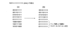
図5はスケール長を8ビットとした場合のクリップ処理の説明図であり、図5(a),(b)は入力信号が処理される前と後のレジスタ内の符号の例であり、(a)はクリップ処理前のレジスタ内の符号の例を示し、(b)はクリップ処理後のレジスタ内の符号の例を示す。図5(a)でレジスタ内の符号「00101111」〜「01111111」は8ビットでは「0101111」〜「1111111」であり規定されたスケール長(8ビット)を越えていないのでクリップ処理後のレジスタ内の符号は図5(b)に示すように「00101111」〜「01111111」となり、クリップ処理の前後でレジスタ内の符号は変換されないが、図5(a)でレジスタ内の符号「10111100」〜「101011000」については規定されたスケール長(8ビット)を越え9ビットで示されているので、クリップ処理によりレジスタ内の符号を8ビットについてフルスケール「1111111」に変換する。従ってレジスタ内は図5(b)に示されるように「01111111」〜「01111111」となる。 FIG. 5 is an explanatory diagram of clip processing when the scale length is 8 bits, and FIGS. 5A and 5B are examples of codes in the register before and after the input signal is processed. a) shows an example of the code in the register before the clip process, and (b) shows an example of the code in the register after the clip process. In FIG. 5A, the codes “00101111” to “01111111” in the register are “01011111” to “1111111” in 8 bits and do not exceed the specified scale length (8 bits). As shown in FIG. 5B, the codes are “00101111” to “01111111”, and the codes in the register are not converted before and after the clipping process. However, in FIG. 5A, the codes “10111100” to “10111100” Since “101011000” exceeds the specified scale length (8 bits) and is indicated by 9 bits, the code in the register is converted to full scale “1111111” for 8 bits by clip processing. Therefore, the registers are “01111111” to “01111111” as shown in FIG.
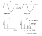
しかしながら、前記(1),(2)の場合、クリップ処理方式では図6(入出力信号波形とそのスペクトラム)に示すように入力信号のスペクトラムを基本波とする高調波が形成される(図6(b’)参照)。また、クリップする部分が多いほど高調波成分も大きく、広範囲(高域まで延びる)となり、その成分のうちサンプリング周波数の1/2より高い周波数成分はD/A変換により折り返し雑音となり、音質を劣化させるという問題点があった(図6で、(a)はクリップ処理前の入力信号波形、(b)はクリップ処理後の入力信号波形、(a’)はクリップ処理前の入力信号波形のスペクトラム、(b’)はクリップ処理後の入力信号波形のスペクトラムである)。なお、前記(2)の場合で上述の問題点の回避策として、図7に示すようにイコライザのゲインに応じて単純に出力信号の信号レベルを減衰させる方法もあったが、イコライザを作動させることにより音量が下がってしまうという問題点があった。 However, in the case of (1) and (2), in the clip processing method, as shown in FIG. 6 (input / output signal waveform and its spectrum), harmonics having the spectrum of the input signal as a fundamental wave are formed (FIG. 6). (See (b ')). In addition, as the clipped portion increases, the harmonic component becomes larger and becomes a wide range (extends to a high frequency range). Among the components, the frequency component higher than 1/2 of the sampling frequency becomes aliasing noise by D / A conversion, and the sound quality is deteriorated. (In FIG. 6, (a) is the input signal waveform before clip processing, (b) is the input signal waveform after clip processing, and (a ') is the spectrum of the input signal waveform before clip processing.) (B ′) is the spectrum of the input signal waveform after the clip processing). In the case of (2), there is a method of simply attenuating the signal level of the output signal according to the gain of the equalizer as shown in FIG. As a result, there was a problem that the volume was lowered.
本発明は、(イ)符号化された音楽信号をDSPなどのプロセッサーで処理を行う場合にクリップ処理を抑制し、折り返し雑音による影響を軽減する、デジタル信号処理方式の提供、及び、(ロ)符号化された信号がフィルタ処理によって規定されたスケールを越えても、クリップ処理することなく、且つ、音量感の変化を極力抑制し得るデジタル信号処理方式の提供を目的とする。 The present invention provides (a) a digital signal processing method that suppresses clip processing when an encoded music signal is processed by a processor such as a DSP and reduces the influence of aliasing noise, and (b) An object of the present invention is to provide a digital signal processing method that can suppress a change in volume feeling as much as possible without performing a clipping process even if an encoded signal exceeds a scale defined by a filter process.
上記の課題を解決するため、本発明のデジタル信号処理方式は、規定されたスケールを越えたデジタル信号を前記規定されたスケール内の信号として変換するデジタル信号処理方式であって、下記(1)、(2)、(3)及び(4)のステップを含むことを特徴とする。
(1)予め複数組の信号変換係数をメモリに格納する。
(2)可変的に設定された信号利得と、設定された音量レベル設定値との和を求める。
(3)ステップ(2)で求めた前記信号利得と前記音量レベル設定値との和に基づいて、ステップ(1)でメモリに格納した複数組の信号変換係数の中から、一組の信号変換係数を読み出す。
(4)ステップ(3)で読み出した一組の信号変換係数によって規定される所定の変換式により入力信号を変換して、出力信号Yを得る。
In order to solve the above problems, a digital signal processing system according to the present invention is a digital signal processing system for converting a digital signal exceeding a specified scale as a signal within the specified scale. , (2), (3) and (4).
(1) A plurality of sets of signal conversion coefficients are stored in the memory in advance.
(2) The sum of the variably set signal gain and the set volume level setting value is obtained.
(3) Based on the sum of the signal gain and the volume level setting value obtained in step (2), a set of signal conversions from among a plurality of sets of signal conversion coefficients stored in the memory in step (1) Read the coefficient.
(4) The input signal is converted by a predetermined conversion formula defined by the set of signal conversion coefficients read in step (3), and the output signal Y is obtained.
また、本発明のデジタル信号処理方式において、ステップ(4)が、読み出した信号変換係数a,bと入力信号Xを基に下記変換式(A)により出力信号Yを得る段階であるようにしてもよい。
Y=X・(a−b・|X|)…(A)
In the digital signal processing system of the present invention, step (4) is a step of obtaining an output signal Y by the following conversion equation (A) based on the read signal conversion coefficients a and b and the input signal X. Also good.
Y = X · (ab− | X |) (A)
本発明のデジタル信号処理方式によれば、クリップ処理を行うことなく、可変的に設定された信号利得と音量レベル設定値に基づいて、信号変換係数を得て、該信号変換係数と入力信号を基に所定の変換式により出力信号Yを得る。 According to the digital signal processing system of the present invention, without performing clipping processing, a signal conversion coefficient is obtained based on a variably set signal gain and volume level setting value, and the signal conversion coefficient and the input signal are obtained. Based on this, an output signal Y is obtained by a predetermined conversion formula.
これにより、フィルタでのブースト量が出力レベルを規定するボリュームレベル設定値で相殺される場合には、出力信号=入力信号となるので出力信号の歪みやレベルの低下が生ぜず、フィルタでのブースト量が相殺されない場合でもクリップ処理していないので、出力信号が著しく歪むこともなく、また、イコライザのゲインに応じて出力信号を単純に減衰させる場合に比べて音量が大きく劣化することもない。 As a result, when the amount of boost in the filter is canceled by the volume level setting value that regulates the output level, the output signal is equal to the input signal, so there is no distortion of the output signal or lowering of the level. Even if the amount is not canceled, the clipping process is not performed, so that the output signal is not significantly distorted, and the volume is not greatly deteriorated as compared with the case where the output signal is simply attenuated according to the gain of the equalizer.
以下、図面を参照しつつ本発明の実施の形態について説明する。 Hereinafter, embodiments of the present invention will be described with reference to the drawings.
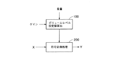
図1は本発明のデジタル信号処理方式の概要を示すブロック図であり、信号処理は大別して音量レベルを算出し、符号(信号)処理用係数を読み出す音量レベル設定値算出処理100と読み出された符号処理用係数に基づいて入力符号(信号)Xの符号変換を行い、出力符号Yを得る符号(信号)変換処理200とからなる。
FIG. 1 is a block diagram showing an outline of a digital signal processing system according to the present invention. Signal processing is roughly divided into a volume level set
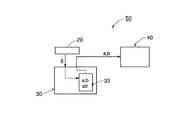
図2は本発明のデジタル信号処理方式を適用した装置50の一実施例の構成を示すブロック図であり、装置50はパラメータ(中心周波数f0,Q(先鋭度),ゲイン)を入力するためのパラメータ入力装置20,マイクロコンピュータ30,及びDSP40を備え、マイクロコンピュータ30で音量レベル設定値算出処理100を、DSP40で符号変換処理200を分担している。
FIG. 2 is a block diagram showing the configuration of an embodiment of the
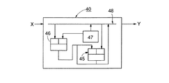
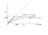
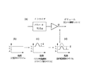
また、図3はDSP40による処理を説明するためのブロック図であり、図4は本発明のデジタル信号処理方式における入出力符号変換特性の例を示す図である。
まず、マイクロコンピュータ30による処理について図1,図2により説明する。まず、メモリ33には予め符号処理用係数a,bの組を格納しておく。パラメータ入力装置20を介して設定されたゲインgと現在設定されているボリュームレベル設定値attを加算してg+attを求め、その演算結果を基に、メモリ33に格納されている係数a,bを読み出してDSP40に転送する。ここで、係数a及びbは後述のDSP40での符号変換の基となる式(2)における係数と対応するものであり、(g+att)<0の場合には、a=1.0,b=0で、逆に、(g+att)>0の場合には、図4に示すように最大(g+att)だけ圧縮するようなカーブをもつ曲線となる係数を設定しておく。なお、現在設定されているパラメータ(中心周波数f0,先鋭度Q,ゲイン)は変更される都度、マイクロコンピュータ30のメモリ33上で新しい値に書き換えられる。
FIG. 3 is a block diagram for explaining processing by the
First, processing by the
次に、DSP40での処理について図3により説明する。なお、DSP40で行う符号変換処理の基となる変換式(A)を下記に示す。
Y=X・(a−b・|X|)…(A)
ここで、Xは入力符号、Yは出力符号、a,bはパラメータである。
マイクロコンピュータ30から転送された係数a,bは係数メモリ33に格納され、以下の処理に用いられる。
Next, processing in the
Y = X · (ab− | X |) (A)
Here, X is an input code, Y is an output code, and a and b are parameters.
The coefficients a and b transferred from the
まず、入力符号Xを演算器45に転送し、絶対値|X|を求める。次に、係数メモリ47から係数bを読み出して乗算器46に転送しb・|X|を求め演算器45に転送する。更に、係数メモリ47から係数aを読み出して演算器45に転送しa−b・|X|を求める。最後にa−b・|X|の結果と入力符号Xを乗算器46へ転送し、求めた値X・(a−b・|X|)を出力符号として出力する。
First, the input code X is transferred to the
これにより、フィルタでのブースト量gが出力レベルを規定するボリュームレベル設定値attで相殺される場合には、出力信号=入力信号となるので出力信号の歪みやレベルの低下が生じない。一方、フィルタでのブースト量gが相殺されない場合((g+att)>0)でもクリップ処理していないので、出力信号が著しく歪むこともなく、また、イコライザのゲインに応じて出力信号を単純に減衰させる場合に比べて音量が大きく劣化することもない。 As a result, when the boost amount g in the filter is canceled by the volume level set value att that defines the output level, the output signal is equal to the input signal, so that the output signal is not distorted or the level is not lowered. On the other hand, even when the boost amount g in the filter is not canceled ((g + att)> 0), since the clipping process is not performed, the output signal is not significantly distorted, and the output signal is simply attenuated according to the gain of the equalizer. Compared with the case of making it, a sound volume does not deteriorate greatly.
20 パラメータ入力装置
30 マイクロコンピュータ
33 メモリ
40 DSP
45 演算器
46 乗算器
47 係数メモリ
50 装置
20
45
Claims (2)
(1)予め複数組の信号変換係数をメモリに格納する。
(2)可変的に設定された信号利得と、設定された音量レベル設定値との和を求める。
(3)ステップ(2)で求めた前記信号利得と前記音量レベル設定値との和に基づいて、ステップ(1)でメモリに格納した複数組の信号変換係数の中から、一組の信号変換係数を読み出す。
(4)ステップ(3)で読み出した一組の信号変換係数によって規定される所定の変換式により入力信号を変換して、出力信号Yを得る。 A digital signal processing system for converting a digital signal exceeding a specified scale by signal processing as a signal within the specified scale, wherein the following (1), (2), (3) and (4) A digital signal processing system comprising steps.
(1) A plurality of sets of signal conversion coefficients are stored in the memory in advance.
(2) The sum of the variably set signal gain and the set volume level setting value is obtained.
(3) Based on the sum of the signal gain and the volume level setting value obtained in step (2), a set of signal conversions from among a plurality of sets of signal conversion coefficients stored in the memory in step (1) Read the coefficient.
(4) The input signal is converted by a predetermined conversion formula defined by the set of signal conversion coefficients read in step (3), and the output signal Y is obtained.
ステップ(4)が、読み出した信号変換係数a,bと入力信号Xを基に下記変換式(A)により出力信号Yを得る段階であることを特徴とするデジタル信号処理方式。
Y=X・(a−b・|X|)…(A)
The digital signal processing system according to claim 1,
A digital signal processing method, wherein step (4) is a step of obtaining an output signal Y by the following conversion equation (A) based on the read signal conversion coefficients a and b and the input signal X.
Y = X · (ab− | X |) (A)
Priority Applications (1)
| Application Number | Priority Date | Filing Date | Title |
|---|---|---|---|
| JP2004371507A JP4021438B2 (en) | 2004-12-22 | 2004-12-22 | Digital signal processing method |
Applications Claiming Priority (1)
| Application Number | Priority Date | Filing Date | Title |
|---|---|---|---|
| JP2004371507A JP4021438B2 (en) | 2004-12-22 | 2004-12-22 | Digital signal processing method |
Related Parent Applications (1)
| Application Number | Title | Priority Date | Filing Date |
|---|---|---|---|
| JP18039894A Division JP3713289B2 (en) | 1994-07-11 | 1994-07-11 | Digital signal processing method |
Publications (2)
| Publication Number | Publication Date |
|---|---|
| JP2005198280A true JP2005198280A (en) | 2005-07-21 |
| JP4021438B2 JP4021438B2 (en) | 2007-12-12 |
Family
ID=34824680
Family Applications (1)
| Application Number | Title | Priority Date | Filing Date |
|---|---|---|---|
| JP2004371507A Expired - Fee Related JP4021438B2 (en) | 2004-12-22 | 2004-12-22 | Digital signal processing method |
Country Status (1)
| Country | Link |
|---|---|
| JP (1) | JP4021438B2 (en) |
Cited By (1)
| Publication number | Priority date | Publication date | Assignee | Title |
|---|---|---|---|---|
| JP2016171447A (en) * | 2015-03-12 | 2016-09-23 | キヤノン株式会社 | Audio processing apparatus and audio processing method |
Families Citing this family (1)
| Publication number | Priority date | Publication date | Assignee | Title |
|---|---|---|---|---|
| JP6803842B2 (en) | 2015-04-13 | 2020-12-23 | ハネウェル・インターナショナル・インコーポレーテッドHoneywell International Inc. | Polysiloxane formulations and coatings for optoelectronic applications |
-
2004
- 2004-12-22 JP JP2004371507A patent/JP4021438B2/en not_active Expired - Fee Related
Cited By (1)
| Publication number | Priority date | Publication date | Assignee | Title |
|---|---|---|---|---|
| JP2016171447A (en) * | 2015-03-12 | 2016-09-23 | キヤノン株式会社 | Audio processing apparatus and audio processing method |
Also Published As
| Publication number | Publication date |
|---|---|
| JP4021438B2 (en) | 2007-12-12 |
Similar Documents
| Publication | Publication Date | Title |
|---|---|---|
| JP4376489B2 (en) | Frequency domain post-filtering method, apparatus and recording medium for improving the quality of coded speech | |
| JP2015050685A (en) | Audio signal processing apparatus and method, and program | |
| US20020173865A1 (en) | Digital audio signal processing | |
| US8498429B2 (en) | Acoustic correction apparatus, audio output apparatus, and acoustic correction method | |
| JP2006500809A5 (en) | ||
| US10291994B2 (en) | Determination method and apparatus for preset of audio equalizer (AEQ) | |
| JPWO2010041381A1 (en) | Signal processing circuit | |
| JP4787316B2 (en) | Digital signal processing apparatus and overtone generation method | |
| JP4021438B2 (en) | Digital signal processing method | |
| JP2007537630A (en) | Digital filter design system and method | |
| US9871497B2 (en) | Processing audio signal to produce enhanced audio signal | |
| JP2015075345A (en) | Sound field measurement device, sound field measurement method and sound field measurement program | |
| JP5103606B2 (en) | Signal processing device | |
| US7346639B2 (en) | Method and apparatus for suppressing limit cycles in noise shaping filters | |
| JPH0822452A (en) | Digital signal processing system | |
| CN114974196B (en) | Noise reduction method and device capable of dynamically controlling noise reduction range, computer equipment and storage medium | |
| JP4223441B2 (en) | Noise reduction method, apparatus for implementing the method, program, and recording medium therefor | |
| JP4963955B2 (en) | Signal processing method, signal processing apparatus, and program | |
| JP2006114998A (en) | Digital signal processing system | |
| CN101479790B (en) | Noise synthesis | |
| JP4892899B2 (en) | Digital signal processing system | |
| JP2006162774A (en) | Signal processing device | |
| CN107077862A (en) | Digital speech processing device, digital speech processing method, digital speech processing program | |
| JP6511988B2 (en) | Digital voice processing apparatus, digital voice processing method, digital voice processing program | |
| Klein et al. | Externally linear time invariant digital signal processors |
Legal Events
| Date | Code | Title | Description |
|---|---|---|---|
| A131 | Notification of reasons for refusal |
Free format text: JAPANESE INTERMEDIATE CODE: A131 Effective date: 20061031 |
|
| A521 | Written amendment |
Free format text: JAPANESE INTERMEDIATE CODE: A523 Effective date: 20061215 |
|
| A131 | Notification of reasons for refusal |
Free format text: JAPANESE INTERMEDIATE CODE: A131 Effective date: 20070327 |
|
| A521 | Written amendment |
Free format text: JAPANESE INTERMEDIATE CODE: A523 Effective date: 20070523 |
|
| A131 | Notification of reasons for refusal |
Free format text: JAPANESE INTERMEDIATE CODE: A131 Effective date: 20070703 |
|
| A521 | Written amendment |
Free format text: JAPANESE INTERMEDIATE CODE: A523 Effective date: 20070827 |
|
| TRDD | Decision of grant or rejection written | ||
| A01 | Written decision to grant a patent or to grant a registration (utility model) |
Free format text: JAPANESE INTERMEDIATE CODE: A01 Effective date: 20070918 |
|
| A61 | First payment of annual fees (during grant procedure) |
Free format text: JAPANESE INTERMEDIATE CODE: A61 Effective date: 20070926 |
|
| FPAY | Renewal fee payment (event date is renewal date of database) |
Free format text: PAYMENT UNTIL: 20101005 Year of fee payment: 3 |
|
| R150 | Certificate of patent or registration of utility model |
Free format text: JAPANESE INTERMEDIATE CODE: R150 |
|
| FPAY | Renewal fee payment (event date is renewal date of database) |
Free format text: PAYMENT UNTIL: 20111005 Year of fee payment: 4 |
|
| FPAY | Renewal fee payment (event date is renewal date of database) |
Free format text: PAYMENT UNTIL: 20121005 Year of fee payment: 5 |
|
| FPAY | Renewal fee payment (event date is renewal date of database) |
Free format text: PAYMENT UNTIL: 20121005 Year of fee payment: 5 |
|
| FPAY | Renewal fee payment (event date is renewal date of database) |
Free format text: PAYMENT UNTIL: 20131005 Year of fee payment: 6 |
|
| LAPS | Cancellation because of no payment of annual fees |