JP2005197823A - Illegitimate access control apparatus between firewall and router - Google Patents
Illegitimate access control apparatus between firewall and router Download PDFInfo
- Publication number
- JP2005197823A JP2005197823A JP2003435587A JP2003435587A JP2005197823A JP 2005197823 A JP2005197823 A JP 2005197823A JP 2003435587 A JP2003435587 A JP 2003435587A JP 2003435587 A JP2003435587 A JP 2003435587A JP 2005197823 A JP2005197823 A JP 2005197823A
- Authority
- JP
- Japan
- Prior art keywords
- router
- unauthorized access
- firewall
- address
- access control
- Prior art date
- Legal status (The legal status is an assumption and is not a legal conclusion. Google has not performed a legal analysis and makes no representation as to the accuracy of the status listed.)
- Withdrawn
Links
Images


Classifications
-
- H—ELECTRICITY
- H04—ELECTRIC COMMUNICATION TECHNIQUE
- H04L—TRANSMISSION OF DIGITAL INFORMATION, e.g. TELEGRAPHIC COMMUNICATION
- H04L63/00—Network architectures or network communication protocols for network security
- H04L63/02—Network architectures or network communication protocols for network security for separating internal from external traffic, e.g. firewalls
- H04L63/0227—Filtering policies
-
- H—ELECTRICITY
- H04—ELECTRIC COMMUNICATION TECHNIQUE
- H04L—TRANSMISSION OF DIGITAL INFORMATION, e.g. TELEGRAPHIC COMMUNICATION
- H04L63/00—Network architectures or network communication protocols for network security
- H04L63/10—Network architectures or network communication protocols for network security for controlling access to devices or network resources
- H04L63/104—Grouping of entities
-
- H—ELECTRICITY
- H04—ELECTRIC COMMUNICATION TECHNIQUE
- H04L—TRANSMISSION OF DIGITAL INFORMATION, e.g. TELEGRAPHIC COMMUNICATION
- H04L63/00—Network architectures or network communication protocols for network security
- H04L63/14—Network architectures or network communication protocols for network security for detecting or protecting against malicious traffic
- H04L63/1441—Countermeasures against malicious traffic
- H04L63/1458—Denial of Service
Abstract
Description
本発明は、ファイアウォール及びルータでの不正アクセス制御装置に関する。 The present invention relates to an unauthorized access control device in a firewall and a router.
近年の通信技術の発達により、インターネットなどのネットワークに多くの情報処理端末が接続されている。しかし、ネットワークに接続されている情報処理端末のユーザは良心的とは限らず、ハッカーと呼ばれる人たちがいる。ハッカーは、他人の情報処理端末に不正にアクセスし、秘匿性の高い情報を勝手に取得したり、侵入した情報処理端末をハッカーが勝手に操作するなどを行い、侵入された側の安全を脅かす。 With the recent development of communication technology, many information processing terminals are connected to a network such as the Internet. However, users of information processing terminals connected to the network are not always conscientious, and there are people called hackers. Hackers illegally access information processing terminals of other people, acquire highly confidential information without permission, and hackers operate the information processing terminals that have intruded, threatening the security of the compromised side. .
このような、不正なアクセスに対処するため、今日、情報処理端末が接続されているネットワークの情報処理端末への入り口にファイアウォールとルータを設けることによって対処することが多く行われている。ファイアウォールは不正アクセスを検出して、不正アクセスを遮断し、ルータの場合は、ユーザがアクセス拒否のアドレスを設定して、当該アドレスからの不正アクセスを拒否するなどが行われる。 In order to deal with such unauthorized access, many countermeasures have been taken today by providing a firewall and a router at the entrance to the information processing terminal of the network to which the information processing terminal is connected. The firewall detects unauthorized access and blocks unauthorized access. In the case of a router, the user sets an address for which access is denied and refuses unauthorized access from the address.
しかし、従来は、ファイアウォールは、レイヤ2〜レイヤ7までの各レイヤでのアクセス制御ポリシーに基づき、アクセス制御を行うため、高度な制御を実現可能であるが、ネットワークを流れるパケットのデータの内部まで識別するために、高速な制御が困難であった。
Conventionally, however, the firewall performs access control based on the access control policy in each layer from
ルータは、ハードレベルでのアクセス制御機能を実装し、高速な制御が可能であるが、レイヤ4〜レイヤ7のレイヤでのアクセス制御が困難であった。
このため運用管理者が、ファイアウォールでのアクセス制御ログ情報を参照し、不正なアクセスを検知した場合に、ルータに該当トラフィックを拒否するフィルタリングポリシーを手動で設定する運用としていた。
The router implements an access control function at a hardware level and can perform high-speed control, but access control in layers 4 to 7 is difficult.
For this reason, the operation administrator refers to the access control log information in the firewall, and when an unauthorized access is detected, the operation administrator manually sets a filtering policy for denying the traffic.
特許文献1には、外部ネットワークから企業内情報ネットワークへの不正アクセスを検出し、不正パケットの送信元端値を可能とするネットワーク監視システムが開示されている。
特許文献2では、ルータ、スイッチ、ファイアウォール等の各機器の保有するフィルタリングポリシーレベルでフィルタリングを行っている。しかし、他の機器の異なるレイヤでのフィルタリングポリシーへの変換適用までは実施しておらず、フィルタリングポリシーの設定はセキュリティ運用管理者が入力する方式をとっている。
In
特許文献3では、複数のファイアウォール装置のフィルタリングヒット状況を外部の管理装置に自動転送し、各ファイアウォールからの情報を基に最適なフィルタリング情報を自動的に再更新し、各ファイアウォール装置に自動転送・反映する方式が開示されている。
従来技術の場合、ファイアウォールとルータは別のノードであり、ファイアウォールでの異常検出をルータのフィルタリングポリシー設定に自動的に反映することができず、運用管理者による監視及び手動操作が必要であった。また、一時的にファイアウォールが過負荷状態となる問題があった。 In the case of the conventional technology, the firewall and the router are separate nodes, and the abnormality detection in the firewall cannot be automatically reflected in the filtering policy setting of the router, and monitoring and manual operation by the operation administrator are necessary. . There was also a problem that the firewall was temporarily overloaded.
また、ファイアウォールでの異常検出を、ルータでのフィルタリングポリシー設定による不当pkt(pktはパケットの省略)の高速な破棄に連動することができない。
ルータでのフィルタリング動作によるパケット破棄状況と、ファイアウォールでのフィルタリング動作によるパケット破棄状況の双方を確認しないと不正アクセスの継続状況を確認できないという問題もある。
In addition, anomaly detection at the firewall cannot be linked to high-speed discard of illegal pkt (pkt is an abbreviation of packet) due to a filtering policy setting at the router.
There is also a problem that the continuation status of unauthorized access cannot be confirmed unless both the packet discard status due to the filtering operation at the router and the packet discard status due to the filtering operation at the firewall are confirmed.
更に、ファイアウォールで検出した異常状態に対し、ルータにフィルタリングポリシーを追加した場合、その解除可否の確認、および解除指示を運用管理者が、ルータにアクセスして行う必要がある。 Furthermore, when a filtering policy is added to a router for an abnormal state detected by a firewall, it is necessary for the operation administrator to access the router to confirm whether or not to cancel the filtering policy.
ファイアウォールがDOS/DDOS攻撃を検知している状態において、ルータでのフィルタリングポリシー設定を行う際、ルータとファイアウォール間の通信路を使用すると、トラフィックが多くなってしまうため、操作ができない場合が発生し得る。 When the firewall detects a DOS / DDOS attack, when setting the filtering policy in the router, if the communication path between the router and the firewall is used, the traffic will increase and the operation may not be possible. obtain.
複数のルータを経由してファイアウォールと接続されている場合において、DOS/DDOS攻撃の送信元トラフィックの入り口となっているルータを特定し、ルータのフィルタリングポリシーを適用するまでに時間がかかり、その間の業務が停止してしまう。 When connecting to a firewall via multiple routers, it takes time to identify the router that is the source of the DOS / DDOS attack source traffic and apply the router's filtering policy. Business stops.
特許文献1では、ファイアウォールとルータの連携により不正アクセスを検知しているが、その不正アクセスを偽装サーバに到達させているため、大量の不正パケットが送られてくる場合、ファイアウォールとルータ間のネットワークがいっぱいになり、正しいパケットを受け付けられなくなる可能性が高い。特に、特許文献1の技術では、DOS/DDOS攻撃時に、ファイアウォールや偽装サーバ、探知装置が動作不能となったり、トラフィック監視装置からファイアウォール、ルータへのフィルタリングルールの適用が、DOS/DDOS攻撃での負荷によりファイアウォールからルータへ指示できない可能性が高い。
In
本発明の課題は、ファイアウォールとルータの連携により、高速、且つ、正常なアクセスを常に正常に処理できる不正アクセス制御装置を提供することである。 An object of the present invention is to provide an unauthorized access control apparatus that can always process normal access normally at high speed by cooperation of a firewall and a router.
本発明の不正アクセス制御装置は、外部のネットワークに接続されたルータとルータに接続されたファイアウォールとが連携して不正アクセスを制御する不正アクセス制御装置において、アクセス元のアドレスを指定して、ハードウェアのレベルで、当該アドレスから送られてくるパケットを破棄するルータと、設定されたアクセス制御ポリシーに基づいて、不正アクセスを検出し、検出した不正アクセスの発信元のアドレスを特定し、不正アクセスの発信元のアドレスを遮断するための該ルータへのコマンドを該ルータ手段に送信し、フィルタリングのポリシー設定をすることによって、該ルータが不正アクセスのアドレスからのパケットを破棄するよう自動的に設定するファイアウォールとを備えることを特徴とする。 An unauthorized access control apparatus according to the present invention is an unauthorized access control apparatus in which a router connected to an external network and a firewall connected to a router cooperate to control unauthorized access. At the hardware level, a router that discards packets sent from the address, and an unauthorized access is detected based on the set access control policy, and the address of the detected unauthorized access is identified, and the unauthorized access The router is automatically set to discard packets from unauthorized access addresses by sending a command to the router to block the originator address and setting a filtering policy. And a firewall.
本発明によれば、ファイアウォールが不正アクセスを検出すると、ファイアウォールは、ルータが不正アクセス元のアドレスからのパケットを破棄するように自動的に設定する。ファイアウォールが自動的にルータの設定を行うことにより、ルータでのハードウェアによる高速なパケット破棄が実現できる。また、ルータとファイアウォールとの間の回線には不正アクセスのパケットが入り込まなくなるので、正規のアクセスを正常に受け付け続けることができる。 According to the present invention, when the firewall detects unauthorized access, the firewall automatically sets the router to discard packets from the unauthorized access source address. Since the firewall automatically configures the router, high-speed packet discard by hardware in the router can be realized. In addition, since unauthorized access packets do not enter the line between the router and the firewall, regular access can be normally accepted.
本発明によれば、ファイアウォールとルータを連携させた不正アクセス制御を行うので、高速且つ高度な不正アクセス拒否制御を行うことができる。 According to the present invention, since unauthorized access control in which a firewall and a router are linked is performed, high-speed and advanced unauthorized access rejection control can be performed.
本発明の実施形態では、以下の構成を採用する。
(1)ファイアウォールでの異常検出時、その送信元IPアドレスを特定し、LAN上に存在するルータに対し、そのルータの使用するフィルタリングコマンドでルータにフィルタリングポリシーを自動設定する機能を、ファイアウォールに実装する。
(2)ファイアウォールでのパケット破棄状況に関する統計情報として、LAN上に存在するルータでのフィルタリング動作によるパケット破棄状況をコマンドにより入手し、上記統計情報に結合して、運用管理者に通知することで、ファイアウォールだけを監視することで、不当アクセス状況を確認する手段を設ける。
(3)(1)でルータに設定したフィルタリングポリシーに対し、(2)の動作により、異常状態の継続有無を定期的に確認し、事前に設定した異常状態脱出の閾値を下回った場合に、自動的に(1)で設定したフィルタリングポリシーを解除するコマンドを投入し、通常状態に復帰する機構を設ける。
(4)ルータとファイアウォール間で帯域を確保した専用の通信路(VLAN等)を確保し、(1)、(2)、(3)の動作を保証する。
(5)複数のルータを経由してファイアウォールと接続されている場合において、ファイアウォールに上記ルータを全て事前登録しておき、DOS/DDOS(Denial Of Service/Distributed Denial Of Service)攻撃検出時に、登録された全てのルータに対して、(1)、(2)、(3)の動作を行う。
In the embodiment of the present invention, the following configuration is adopted.
(1) When an abnormality is detected in the firewall, a function that automatically identifies the source IP address and automatically sets the filtering policy for the router using the filtering command used by the router is implemented in the firewall. To do.
(2) As statistical information on the packet discard status at the firewall, obtain the packet discard status due to the filtering operation at the router on the LAN by using a command, and combine it with the above statistical information to notify the operation manager. By monitoring only the firewall, a means for checking the unauthorized access status is provided.
(3) For the filtering policy set in the router in (1), the operation of (2) periodically checks whether the abnormal state continues or not and falls below the preset abnormal state exit threshold. A mechanism is provided that automatically inputs a command for canceling the filtering policy set in (1) and returns to the normal state.
(4) A dedicated communication path (such as VLAN) that secures a band between the router and the firewall is secured, and the operations of (1), (2), and (3) are guaranteed.
(5) When connected to a firewall via multiple routers, all of the above routers are pre-registered in the firewall and registered when a DOS / DDOS (Denial Of Service / Distributed Denial Of Service) attack is detected. The operations (1), (2), and (3) are performed for all the routers.
DOS/DDOS攻撃により送られてくる不正パケットを破棄することにより、ルータとファイアウォールとの間の回線の容量が大きく消費されてしまうことを防ぎ、正当なアクセスを常に正常に受け付けることを可能としている。 By discarding illegal packets sent by DOS / DDOS attacks, it is possible to prevent a large amount of line capacity between the router and the firewall from being consumed, and to always properly accept legitimate access. .
以下、図面を用いて説明する。
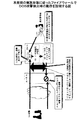
図1は、本発明の実施形態に従ったファイアウォールでDOS攻撃検出時の動作を説明する図である。
Hereinafter, it demonstrates using drawing.
FIG. 1 is a diagram illustrating an operation when a DOS attack is detected by a firewall according to an embodiment of the present invention.
ファイアウォール11(以下、FW)が、事前設定されたフィルタリングポリシーをもとにDOS/DDOS攻撃を検出した場合(1)、ログ出力を行うと同時に、その不正アクセスパケットの送信元IPアドレスを特定する(2)。
When the firewall 11 (hereinafter referred to as FW) detects a DOS / DDOS attack based on a preset filtering policy (1), the
このFW11には、事前にルータ10の外部接続ネットワークのインターフェース名、及びルータ10のフィルタリングコマンド形式を登録しておき、(2)で特定した送信元IPアドレスをキーとしたルータのフィルタリングコマンドを生成し、ルータにコマンド操作のためのリモート接続を行った後、当該コマンドをルータに設定する(3)。ルータ10では、(3)で設定されたフィルタリングポリシーを元に、以降のDOS/DDOS攻撃パケットを遮断・破棄する(4)。以降、(1)〜(4)までの動作を自動的に実施する。運用管理者がFW11のログを見て、不正アクセスを発見したときには、既に、FW11とルータ10が連携して、不正アクセスをフィルタリングしている状態になっている。
In this FW11, the interface name of the external connection network of the
なお、今後、本発明の実施形態の説明において、ルータは、以下の構成をもっているものとする。
1)ルータは、送信元IPアドレス指定によるパケット破棄をハードレベルで実現可能な環境を持ち、このパケット破棄指示を各ルータ固有のコマンド仕様で指定可能とする。また、各ルータは、外部ネットワークに対する接続インターフェースと、サーバ宛のパケットの中継点であるFW側への接続インターフェース、及びルータ装置の運用管理(フィルタリングポリシー設定、状態確認)を行うための専用インターフェースを保持する。また、ルータは、複数台で構成可能で、かつ、異なるルータ機種でも組み合わせて構成可能である。
2)ルータ及びFWの運用管理インターフェースは、ルータとFW間の、正当なユーザとサーバ間通信のために使用するインターフェースとは独立したインターフェースで、かつ、サーバ間通信用インターフェースのトラフィックとは帯域を共有しない、例えば、異なる物理回線を使うとか、同一ケーブル上でVLANを分け、かつ、帯域を運用管理専用に確保しているなどの方式を採用している。
In the following description of the embodiment of the present invention, it is assumed that the router has the following configuration.
1) The router has an environment in which packet discard by specifying the source IP address can be realized at the hardware level, and this packet discard instruction can be specified by a command specification unique to each router. Each router has a connection interface to the external network, a connection interface to the FW side that is a relay point for packets addressed to the server, and a dedicated interface for operation management (filtering policy setting, status check) of the router device. Hold. Also, a plurality of routers can be configured, and different router models can be combined.
2) The operation management interface of the router and FW is an interface that is independent of the interface used between the valid user and the server between the router and the FW, and the bandwidth of the traffic of the server-to-server communication interface For example, different physical lines are used, VLANs are divided on the same cable, and a band is reserved exclusively for operation management.
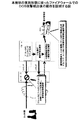
図2は、本発明の実施形態に従ったファイアウォールでのDOS攻撃検出後の動作を説明する図である。
(1)で、FW11からルータ10に設定したフィルタリングポリシーに基づき、ルータ10でDOS/DDOS攻撃パケットを遮断した後は、FW11から定期的にルータ10側のフィルタリング状態表示コマンドを投入することで、破棄パケット数の増加有無を確認し(3)、その状態表示コマンドで得た情報を、FW11のファイルリングポリシー(DOS/DDOS攻撃防御ポリシー)のルールに対応付けて蓄積しているため運用管理者が攻撃の継続を確認するために仮想ノードに対する確認コマンドを投入すると、破棄状態に関する統計情報として受け取る(4)ことができる。このため運用管理者は、FW11がフィルタリング制御をルータにオフロード(パケットの破棄処理をFW11からルータ10に移すこと)しているか否かを意識することなく、状態確認をFW11に対する操作だけで実施することが可能となる。
FIG. 2 is a diagram for explaining the operation after detecting the DOS attack in the firewall according to the embodiment of the present invention.
In (1), after blocking the DOS / DDOS attack packet in the
図3は、本発明の実施形態に従ったDOS攻撃停止時の動作を説明する図である。
(1)によりFW11からルータ10にフィルタリングポリシーを設定し、(2)で、ルータにて攻撃トラフィックに該当するパケットを破棄している状況において攻撃が止まった場合(3)、FW11に事前設定した攻撃状態の解除認識条件(攻撃パケットの時間あたりの数が閾値以下となって、指定した時間経過など)に適合した場合に、自動的に(1)で設定したポリシーを解除するコマンドをファイアウォール(FW11)が投入することで、不要なアクセス制御ルールの残存による、定常状態での余分な負荷の継続を自動的に防止する。
FIG. 3 is a diagram for explaining the operation when the DOS attack is stopped according to the embodiment of the present invention.
When the filtering policy is set from the
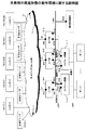
図4は、本発明の実施形態の動作環境に関する説明図である。
なお、同図において、ハッカー1〜5、外部ネットワーク、ルータ1〜3、FW現用装置、FW待機装置、運用管理端末などに付されている数字や記号は、IPアドレス等の装置を特定する識別子の例である。後の図において、これらのIPアドレス等を用いて説明を行う。
FIG. 4 is an explanatory diagram relating to the operating environment of the embodiment of the present invention.
In the figure, numbers and symbols attached to
正当な利用者からのアクセスと、不当なアクセス(悪意あるアクセス)を行うハッカーが混在し得るインターネット等の外部接続ネットワーク15と各ユーザからのアクセス先であるサーバまでの間に、本発明の実施形態で説明するルータ10−1〜10−3及びFW11−1、11−2が存在する。ルータ10−1〜10−3は、送信元IPアドレス指定によるパケット破棄をハード(チップ)のコマンド仕様で指定可能である。また、各ルータ10−1〜10−3は、外部ネットワーク15に対する接続インターフェース、及びルータ装置の運用管理(フィルタリングポリシー設定、状態確認)を行うための専用インターフェースを保持する。また、ルータ10−1〜10−3は、複数台で構成可能、かつ、異なるルータ機種でも実現可能である。FW11−1、11−2は、1台または2台(FWの信頼性を高める場合)で構成可能であり、ルータ10−1〜10−3と直接接続されたインターフェース、サーバへの接続インターフェース、及びFWの運用管理(DOS/DDOS攻撃防御ポリシー、ルータ連携環境設定、DOS/DDOS攻撃防御状況確認)を行うための専用インターフェースを保有する。ルータ10−1〜10−3及びFW11−1、11−2の運用管理インターフェースは、ルータ10−1〜10−3とFW11−1、11−2間の、正当なユーザとサーバ間通信(以降、業務通信と略す)のために使用するインターフェースとは独立したインターフェースで、かつ、業務インターフェースのトラフィックとは帯域を共有しない方式(異なる物理結線または、同一ケーブル上でVLANを分け、かつ帯域を運用管理専用に確保)を保有する。
Implementation of the present invention between an
FW11−1、11−2は、2台でホットスタンバイ動作により使用することが可能であり、この場合、業務通信用インターフェースに関し、ルータ側およびサーバ側で、各々各ネットワークに共通な2台のファイアウォール(以降FWと略す)に対し1つの共用IPを付与し、本IPを仮想IPとして現用FW装置11−1が通信に使用する機能を保持する。また、運用管理用インターフェースにおいても共用IPを付与し、運用管理者は、本IPを運用操作対象FWとして運用操作することで、運用管理者に2台のFWの意識及びFWの動作状態(現用・待機)の意識を不用とする機能を保有する。 Two FWs 11-1 and 11-2 can be used by hot standby operation. In this case, two firewalls that are common to each network on the router side and the server side for the business communication interface. One shared IP is assigned to (hereinafter abbreviated as FW), and this IP is used as a virtual IP and the function used by the active FW device 11-1 for communication is held. In addition, a shared IP is also assigned to the operation management interface, and the operation manager operates the IP as an operation target FW, thereby allowing the operation manager to recognize the two FWs and the FW operating status (currently used).・ Has a function that eliminates the need for standby).
図5は、ファイアウォールに環境定義情報として運用管理者が設定する情報をテーブルとして表した図である。図5におけるテーブルの内容は、例として図4の情報を基に設定したものである。 FIG. 5 is a table showing information set by the operation manager as environment definition information in the firewall. The contents of the table in FIG. 5 are set based on the information in FIG. 4 as an example.
連携対象ルータとは、外部ネットワークに接続されたルータであり、図4のルータ1〜ルータ3を示す。また、これらの各ルータ単位に図5に示す各情報を設定する。制御用IPアドレスとは、FWからルータに対するコマンド制御を行うためのルータ側IPであり、図4の運用管理用インターフェース上のルータ側IPを示す。制御用アカウント・パスワードは、FWから各ルータに対する運用管理操作を行うための接続を行う際、ルータ側の認証情報として、登録されているものを設定する。接続手順・接続ポート番号は、上記接続を行う際に使用するポート番号、及び、接続する場合telnetまたはsshのいずれの手順を使用するかを示し、接続手順は、ルータ側でサポートされているtelnet/sshのいずれかを設定する。
The cooperation target router is a router connected to an external network, and shows
ルータ種別とは、後に図6で示すようにルータのメーカ、機種によりフィルタリング等の機能で提供するルータのコマンド仕様が相違する場合に、適切なコマンド仕様を選択するためのルータ種別識別情報であり、FW内に実装されている図6のテーブルに登録されたルータが本実施形態での対象ルータとなる。 The router type is router type identification information for selecting an appropriate command specification when the command specification of the router provided by a function such as filtering differs depending on the manufacturer and model of the router as shown in FIG. The router registered in the table of FIG. 6 installed in the FW is the target router in this embodiment.
DOS防御インターフェースは、ルータにフィルタリングルールを適用する際、インターフェースの指定が可能であるかを示すものであり、指定可能な場合には、更に、外部ネットワーク接続インターフェース名を指定する。また、この指定はルータによっては、任意の指定が可能であることが考えられるが、この場合、ルータ側の処理能力により、特に問題が無ければ、外部ネットワークだけでなく、全インターフェースを対象とすることもできるものと想定する。 The DOS protection interface indicates whether an interface can be specified when a filtering rule is applied to the router. If the interface can be specified, an external network connection interface name is further specified. In addition, depending on the router, it may be possible to specify any designation, but in this case, if there is no particular problem due to the processing capacity of the router, not only the external network but also all interfaces are targeted. Assume that you can also.
フィルタリングルール番号は、ルータに対するフィルタリングルールをコマンドにより設定する際に、複数のルールを識別するための番号を、FW側で保持するものである。また、ルータへのフィルタリングルールは、本実施形態によるFWからの自動設定以外にも、運用管理者が事前設定するケースもあるため、本テーブルで設定した番号の範囲を、FWからの自動設定で使用すると共に、その他の番号の範囲をユーザの手動設定で使用することし、これにより、FWでの自動設定と、運用管理者の手動設定で、ルール番号の重複が発生することを回避する。 The filtering rule number is used to hold a number for identifying a plurality of rules on the FW side when a filtering rule for a router is set by a command. In addition to the automatic setting from the FW according to the present embodiment, there are cases where the operation administrator pre-sets the filtering rules for the router, so the range of numbers set in this table can be set by the automatic setting from the FW. In addition to using this, the range of other numbers is used by the user's manual setting, thereby avoiding duplication of rule numbers between the automatic setting at the FW and the manual setting by the operation manager.
図6は、本発明の実施形態に従った、FW装置のファームウェア、あるいは、ソフトウェアとして装置自身に登録されている情報の例を示す図である。
図6のテーブルは、運用管理者は操作しない内部テーブルである。
FIG. 6 is a diagram showing an example of information registered in the device itself as firmware or software of the FW device according to the embodiment of the present invention.
The table in FIG. 6 is an internal table that is not operated by the operation manager.
図6のテーブルは、FW装置が本実施形態で連携可能なルータ装置(機種)に対し、その識別情報をルータ種別という形で与える。FWは、本実施形態での連携ルータ機種を拡張する場合には、本テーブルにルータ種別を新規に追加し、他のテーブル内容に、追加したルータ仕様に基づいた情報を付加する。これにより、新たなルータに対しても本実施形態を適用することができるようになる。 The table of FIG. 6 gives the identification information in the form of router type to the router apparatus (model) that the FW apparatus can cooperate in this embodiment. When the FW expands the cooperative router model in this embodiment, the FW adds a new router type to this table, and adds information based on the added router specifications to other table contents. As a result, the present embodiment can be applied to a new router.
フィルタリングルールコマンド、ルール適用コマンド、状態参照コマンド、フィルタリングルール解除コマンド、ルール適用解除コマンド、インターフェース指定コマンドには、ルータ種別毎に、そのルータの仕様に沿ったコマンドsyntaxを設定する。 In the filtering rule command, the rule application command, the state reference command, the filtering rule cancellation command, the rule application cancellation command, and the interface designation command, a command syntax that conforms to the router specifications is set for each router type.
図7は、運用管理者が、FW装置に対して、FW装置が提供するDOS/DDOS防御機能の使用の有無をポリシーとして設定したFW内部のテーブルの例を示す図である。
検出DOS攻撃種別は、FW装置が提供するDOS防御機能の一覧であり、図7に不正IPパケット受信、不正TCPパケット受信、Ping of Death攻撃、Nimudaワーム、I LOVE YOU攻撃と列挙されているように、各種別単位で、詳細なDOS攻撃としての検出対象/内容が、検出DOS攻撃内容詳細として設定されている。ユーザは、不正IPバージョンなどの一意に識別可能な情報を指定する場合において、GUI(Graphic User Interface)、CLI(Command Line Interface)でユニークな識別子を選択するだけで指定可能な場合や、図7のNimudaワームの詳細検出内容のように複数の識別情報を同様にGUI、CLIで識別子選択・指定する場合、及び、ユーザ自身がこれらの詳細情報を、識別パターンとして個別に設定する場合のいずれでも指定可能である。
FIG. 7 is a diagram illustrating an example of a table inside the FW in which the operation manager sets, as a policy, whether or not the DOS / DDOS protection function provided by the FW device is used for the FW device.
The detected DOS attack type is a list of DOS protection functions provided by the FW device, and it is listed in FIG. 7 as illegal IP packet reception, illegal TCP packet reception, Ping of Death attack, Nimuda worm, and I LOVE YOU attack. In addition, a detection target / content as a detailed DOS attack is set as a detailed detection DOS attack content in various units. When the user designates uniquely identifiable information such as an unauthorized IP version, the user can designate only by selecting a unique identifier using GUI (Graphic User Interface) or CLI (Command Line Interface). As in the case of the detailed detection contents of the Nimuda worm, the identification information is similarly selected / designated by the GUI and CLI, and the detailed information is individually set as an identification pattern by the user. Can be specified.
異常検出閾値は、FW装置としてデフォルト値を保有し、運用管理者が特に指定しない場合は、この値を使用し、運用管理者が特別に、各ルールに対し指定した場合には、指定値が採用され、本テーブルに反映される。設定内容としては、秒あたりの該当pkt受信数を指定し、その数を上回った場合に検知する方法と、1pktでも受信した場合には即座に異常とみなす即時検出(実質的に1pkt/sと同等)の2つの方法がある。 The anomaly detection threshold value has a default value as the FW device, and this value is used when the operation manager does not specify otherwise. When the operation administrator designates each rule specifically, the specified value is Adopted and reflected in this table. As the setting contents, the number of received pkts per second is designated, and a detection method when the number exceeds that number, and immediate detection (substantially 1 pkt / s) that immediately considers an abnormality when even 1 pkt is received. There are two methods.
遮断可否の情報は、攻撃パターンを異常検出閾値以上のpkt数受信時に、異常と認識し遮断する(pkt破棄する)か否かを示す。この情報を遮断と指定した場合に、異常検出、閾値異常のpkt受信時に、異常発生のメッセージ出力と同時に、ルータに対する動的なフィルタリング指示を行う。 The blockability information indicates whether or not an attack pattern is recognized as abnormal when it receives a number of pkts that is equal to or greater than the abnormality detection threshold and is blocked (pkt discarded). When this information is designated as shut-off, upon receiving an abnormality detection and threshold abnormality pkt, a dynamic filtering instruction is given to the router simultaneously with the output of the abnormality occurrence message.
遮断解除時間とは、異常検出後、遮断状態を解除するまでの時間である。
なお、異常検出時時点から遮断解除時間経過時に、その間のルータでのpkt廃棄状況を確認し、その破棄数が異常検出閾値以上であった場合には、遮断時間解除時間経過後であってもルータに対するフィルタリングの解除指示は行わず、この時点から再度、遮断時間解除時間が経過するまで、ルータでのフィルタリング状態を継続する。
The interruption release time is the time until the interruption state is released after an abnormality is detected.
When the shutdown release time has elapsed from the time of abnormality detection, the pkt discard status at the router during that time is confirmed. If the number of discards is equal to or greater than the abnormality detection threshold, even after the shutdown time release time has elapsed The router is not instructed to cancel the filtering, and the filtering state at the router is continued from this point in time until the cutoff time cancellation time elapses again.
図8は、DOS/DDOS攻撃をFWで検出している状態、及び、ルータに対する指示状態を管理するためにFW内部に保持するテーブルの例を示す図である。
図7で示すFWのポリシーテーブルを基に、DOS/DDOS攻撃を検出した場合に、その検出時間、及び検出時の該当pktの送信元IPアドレスと、そのIPアドレスでルータにフィルタリング指示を行った場合の各ルータに対して発行したフィルタリング適用指示コマンドのルール番号をルータ毎に保持している。
FIG. 8 is a diagram illustrating an example of a table held in the FW in order to manage the state in which the DOS / DDOS attack is detected by the FW and the instruction state to the router.
Based on the FW policy table shown in FIG. 7, when a DOS / DDOS attack is detected, the detection time, the source IP address of the corresponding pkt at the time of detection, and a filtering instruction to the router with the IP address The rule number of the filtering application instruction command issued to each router is stored for each router.
本テーブル情報を基に、FWは、DOS/DDOS攻撃検出時に、ルータに対して発行したフィルタリング指示コマンドに対応付けて、攻撃解除時にフィルタリング適用解除指示コマンドを発行するための情報、及び、攻撃の継続状態の確認を行うための情報として使用する。 Based on this table information, the FW is associated with the filtering instruction command issued to the router when the DOS / DDOS attack is detected, and information for issuing the filtering application cancellation instruction command when the attack is released. Used as information for checking the continuation status.
本情報は、FWの現用装置で状態更新が行われるが、更新時には、その差分情報をFW待機装置に転送し、常にFW現用・待機装置間で状態の同期(一致性保証)が行われる。
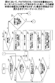
図9は、FWでのDOS/DDOS攻撃検出からルータへのフィルタリング指示までのFW側での動作の流れを示すフローチャートである。
This information is updated by the FW active device. At the time of update, the difference information is transferred to the FW standby device, and the state synchronization (guarantee of consistency) is always performed between the FW active device and the standby device.
FIG. 9 is a flowchart showing an operation flow on the FW side from the DOS / DDOS attack detection in the FW to the filtering instruction to the router.
各ルータは、FWから指示されたフィルタリング指示コマンドを、コマンド操作として動的に受け付け、その状態参照コマンドに対して、フィルタリング指示コマンドによるpkt破棄状態通知、および、フィルタリング適用解除指示コマンドの受け付けを行う。ルータでは、状態が、通常状態→フィルタリング適用中(状態確認コマンド受け付け)→通常状態(フィルタリング適用解除指示コマンド受け付け)の遷移を行う。 Each router dynamically accepts a filtering instruction command instructed by the FW as a command operation, and accepts a pkt discard state notification by a filtering instruction command and a filtering application release instruction command for the state reference command. . In the router, the state transitions from normal state to filtering being applied (status confirmation command received) to normal state (filtering application release instruction command received).
以下に、図9の流れについて説明する。
ステップS10において、FWはパケット(pkt)を受信すると、検出対象のDOS攻撃に一致したか否かの判定を行う。一致しなかった場合には、ステップS11において、全DOS攻撃対象のチェックが完了したか否かについて判断する。ステップS11の判断がNOの場合には、ステップS10に戻る。ステップS11の判断がYESの場合には、処理を終了する。
The flow of FIG. 9 will be described below.
In step S10, when the FW receives the packet (pkt), the FW determines whether or not it matches the detection target DOS attack. If they do not match, it is determined in step S11 whether or not all DOS attack targets have been checked. If the determination in step S11 is no, the process returns to step S10. If the determination in step S11 is yes, the process ends.
すなわち、図7のテーブルを使用し、一致するものがあるか否かを図7の全行(以降エントリと呼ぶ)に対して行い、存在しなかった場合は、DOS/DDOS攻撃検出処理を終了し、通常のpkt受信処理を行う。 That is, the table in FIG. 7 is used to determine whether there is a match for all the rows in FIG. 7 (hereinafter referred to as entries), and when there is no match, the DOS / DDOS attack detection process is terminated. Then, normal pkt reception processing is performed.
ステップS10で、一致するものがあった場合には、そのpkt受信数を+1し、図7のテーブルに保持する。この際、PKT受信数が図7の異常検出閾値以上となった場合には、図5を参照し、図5の連携対象ルータへのフィルタリング適用指示動作を開始する。 If there is a match in step S10, the pkt reception number is incremented by 1 and held in the table of FIG. At this time, if the number of received PKTs is equal to or greater than the abnormality detection threshold in FIG. 7, the filtering application instruction operation to the cooperation target router in FIG. 5 is started with reference to FIG.
異常検出を行った場合には、この異常PKTを以降ルータ側で破棄する必要があるか否かを図5のテーブルを用いて判断する。図5にエントリが1つでも存在した場合には、各エントリに指定されたルータに対するフィルタリング適用指示を開始する(ステップS12)。 When abnormality detection is performed, it is determined using the table of FIG. 5 whether or not the abnormality PKT needs to be discarded on the router side thereafter. If there is even one entry in FIG. 5, a filtering application instruction for the router designated in each entry is started (step S12).
ステップS12の処理において、各ルータにフィルタリング適用指示をコマンドとして指示するための準備処理として、図5のテーブルを用いて、各ルータへのtelnetまたはsshによる接続を行う。このときの、ルータに対する接続手順、ポート番号、制御用IPアドレス、アカウント・パスワード情報は、全て図5の情報を使用する(ステップS13及びS14)。 In the process of step S12, as a preparatory process for instructing each router as a filtering application instruction as a command, connection to each router by telnet or ssh is performed using the table of FIG. At this time, the connection procedure for the router, the port number, the control IP address, and the account / password information all use the information shown in FIG. 5 (steps S13 and S14).
上記処理で、図5の現在処理中のエントリに対応するルータとの接続が完了した場合には、そのルータの種別を図5より抽出し、その種別情報をキーとして図6のエントリを検索し、該当ルータ種別エントリのフィルタリングルールコマンドsyntaxを図5より求める(ステップS15)。 When the connection with the router corresponding to the entry currently being processed in FIG. 5 is completed in the above processing, the type of the router is extracted from FIG. 5, and the entry of FIG. 6 is searched using the type information as a key. Then, the filtering rule command syntax of the corresponding router type entry is obtained from FIG. 5 (step S15).
図5のルータフィルタリング番号より、図8で現在当該ルータに使用しているルール番号以外の番号を抽出し、ステップS15で求めたコマンドsyntaxに本番号と、ステップS10で異常検出した受信PKTの送信元IPアドレスをフィルタリング対象として適用し、そのルータが解釈可能なフィルタリングルールコマンドとして発行を行い、当該ルータへのルール設定を完了する(ステップS16)。 The number other than the rule number currently used for the router in FIG. 8 is extracted from the router filtering number in FIG. 5, and the real number is transmitted to the command syntax obtained in step S15, and the received PKT in which the abnormality is detected in step S10 is transmitted. The original IP address is applied as a filtering target, issued as a filtering rule command that can be interpreted by the router, and rule setting for the router is completed (step S16).
更に、このフィルタリングルールコマンドを、当該ルールで破棄動作の適用として登録するために、フィルタリング適用コマンドを発行する必要があるが、この際ルータによっては、図5のDOS防御対象インターフェースの説明で記述したように、特定のインターフェースに適用する必要がある場合と、ルータの全インターフェースに適用可能な場合があるため、その設定がどうなっているかを図5の当該情報を参照し判断する(ステップS17)。ステップS17の判断がNOの場合には、ステップS20に進み、ステップS17の判断がYESの場合には、ステップS18に進む。 Furthermore, in order to register this filtering rule command as the application of the discard operation in the rule, it is necessary to issue the filtering application command. At this time, depending on the router, it is described in the description of the DOS protection target interface in FIG. Thus, there are cases where it is necessary to apply to a specific interface and cases where it can be applied to all the interfaces of the router, so it is determined with reference to the information in FIG. 5 how the settings are made (step S17). . If the determination in step S17 is NO, the process proceeds to step S20. If the determination in step S17 is YES, the process proceeds to step S18.
図5のDOS防御対象インターフェースでインターフェース指定となっていた場合には、本フィールドからインターフェース名を抽出し、かつ、図6のインターフェースコマンド指定形式を当該ルータのルータ種別の一致するエントリから抽出し、当該ルータに対し、インターフェース指定コマンドを発行する(ステップS18及びS19)。 If the interface is specified in the DOS protection target interface of FIG. 5, the interface name is extracted from this field, and the interface command specification format of FIG. 6 is extracted from the entry corresponding to the router type of the router, An interface designation command is issued to the router (steps S18 and S19).
当該ルータに対し、そのルータのフィルタリング適用コマンドsyntaxを図6のルータ種別の一致するエントリから抽出し、ステップS16で設定したフィルタリングルールコマンドのルール番号と合わせて、ルータに適用指示を行う(ステップS20及びS21)。 The filtering application command syntax of the router is extracted from the entry having the matching router type in FIG. 6 and is applied to the router together with the rule number of the filtering rule command set in step S16 (step S20). And S21).
ステップS21の処理を完了した場合、更に図5のエントリで未実施のルータがあれば、ステップS12の処理から処理を繰り返し実施し、図5の全エントリに対する処理が完了した場合に、本処理を完了する。 When the processing in step S21 is completed, if there is an unimplemented router in the entry in FIG. 5, the processing is repeated from the processing in step S12, and this processing is performed when processing for all entries in FIG. 5 is completed. Complete.
図10及び図11は、図9において、FWでのDOS/DDOS攻撃検出からルータへのフィルタリング指示を行った後に、その継続状態の確認及び攻撃がおさまった場合の解除までの流れを示すフローチャートである。 FIGS. 10 and 11 are flowcharts showing the flow from the detection of the DOS / DDOS attack in the FW to the filtering instruction to the router in FIG. 9 until the confirmation of the continuation state and the cancellation when the attack is stopped. is there.
FWは予め決められた監視時間間隔(運用管理者による設定変更可能)で、DOS/DDOS攻撃の継続の有無を確認する(ステップS25)ステップS25において、監視時間間隔が経過していない場合には、処理を終了する。ステップS25において、監視時間間隔が経過したと判断された場合には、ステップS26に進む。 The FW confirms whether or not the DOS / DDOS attack continues at a predetermined monitoring time interval (settings can be changed by the operation manager) (step S25). If the monitoring time interval has not elapsed in step S25 The process is terminated. If it is determined in step S25 that the monitoring time interval has elapsed, the process proceeds to step S26.
FW装置内の図8のテーブルにおいて、検出時刻の設定されたエントリが存在するか否かを判断する(ステップS26)。ステップS26の判断がNOの場合には処理を終了する。ステップS26の判断がYESの場合には、ステップS27に進む。 In the table of FIG. 8 in the FW device, it is determined whether or not there is an entry for which a detection time is set (step S26). If the determination in step S26 is no, the process ends. If the determination in step S26 is yes, the process proceeds to step S27.
FW装置内の図8のテーブルにおいて、検出時刻の設定されたエントリが存在する場合、その検出ルールとして該当する図7のエントリを参照し、遮断解除時間を確認し、手動となっていないエントリであるかを確認する(ステップS27)
ステップS27で自動解除となっていた場合には、図8の該当エントリの検出時間に図7の該当エントリの遮断解除時間を加えたものが、現時刻以上となっているかを確認する(ステップS28)。ステップS27で自動解除となっていなかった場合には、ステップS26に戻って、次のエントリの処理を行う。
In the table of FIG. 8 in the FW device, if there is an entry with a detection time, refer to the entry of FIG. Check whether there is (step S27)
If it has been automatically canceled in step S27, it is confirmed whether the detection time of the corresponding entry in FIG. 8 plus the blocking release time of the corresponding entry in FIG. 7 is equal to or greater than the current time (step S28). ). If the automatic release has not been canceled in step S27, the process returns to step S26 to process the next entry.
ステップS28で指定時間経過していた場合は、図5に保持する連携対象ルータで、現在、図8で確認中のエントリに対する攻撃が継続しているかを確認するための処理を開始する(ステップS29)。ステップS28において、指定時間経過していない場合には、ステップS26に進み、次エントリの処理に進む。 If the specified time has elapsed in step S28, processing for confirming whether or not the attack on the entry currently being confirmed in FIG. 8 continues in the cooperation target router held in FIG. 5 is started (step S29). ). If the specified time has not elapsed in step S28, the process proceeds to step S26, and the process proceeds to the next entry.
ステップS29における判断がNOの場合には、ステップS35に進む。
ステップS30〜S31で、図5の各ルータに対しても接続を図9のステップS13〜S14と同様に行い、図6の該当ルータエントリの状態参照コマンドのsyntaxを抽出し、コマンドを発行する(ステップS32及びS33)。
If the determination in step S29 is no, the process proceeds to step S35.
In steps S30 to S31, connection to each router in FIG. 5 is performed in the same manner as in steps S13 to S14 in FIG. 9, and the syntax of the status reference command of the corresponding router entry in FIG. 6 is extracted and the command is issued ( Steps S32 and S33).
上記で発行した状態参照コマンドの内容から、図8の当該エントリに対する図5での当該ルータからのpkt削除数を取り出し、図8で前回当該ルータから取り出したpkt削除数と比較し、その増加分を図8の当該エントリに書き込む(ステップS34)。 The number of pkt deletions from the router in FIG. 5 for the entry in FIG. 8 is extracted from the contents of the state reference command issued above, and compared with the number of pkt deletions extracted from the router in FIG. Is written in the entry of FIG. 8 (step S34).
上記処理を図5の全ルータに対し実施した後、ステップS33で求めた図8の当該エントリでの各ルータのpkt破棄数の総和が、図7の当該エントリの異常検出閾値未満であるかを確認し、閾値未満である場合には、破棄解除状態への遷移を行うため、以下の処理を行う。また、閾値以上であった場合には、破棄状態を継続する必要があるため、何もせず、図8の次のエントリに対する確認処理を継続するため、ステップS26に戻る。 After the above processing is performed for all the routers in FIG. 5, whether the total number of pkt discards of each router in the entry in FIG. 8 obtained in step S33 is less than the abnormality detection threshold of the entry in FIG. If it is confirmed that it is less than the threshold value, the following processing is performed to make a transition to the discard cancellation state. If it is equal to or greater than the threshold value, the discard state needs to be continued, so nothing is done and the process returns to step S26 to continue the confirmation process for the next entry in FIG.
ステップS35において、破棄状態解除が必要となった場合には、図5内の各ルータに対し、接続・フィルタリング適用解除コマンド投入・フィルタリングルール解除コマンドの投入を行う。 If it is necessary to cancel the discarding state in step S35, connection / filtering application cancellation command input / filtering rule cancellation command is input to each router in FIG.
すなわち、図11のステップS36において、連携対象ルータがあるか否かを判断する。ステップS36の判断がNOの場合には、図10のステップS26に戻る。ステップS36の判断がYESの場合、ステップS37において、連携対象のルータでアカウント、パスワード、接続手順、接続ポート番号を抽出し、対象ルータに接続する。ステップS38において、連携対象のルータでDOS防御インターフェースの指示があるか否かを判断する。ステップS38の判断がNOの場合には、ステップS40に進み、YESの場合には、ステップS39に進む。 That is, in step S36 of FIG. 11, it is determined whether there is a cooperation target router. If the determination in step S36 is no, the process returns to step S26 in FIG. If the determination in step S36 is YES, in step S37, the account, password, connection procedure, and connection port number are extracted from the cooperation target router and connected to the target router. In step S38, it is determined whether or not there is an instruction for the DOS protection interface in the router to be linked. If the determination in step S38 is no, the process proceeds to step S40. If the determination is yes, the process proceeds to step S39.
ステップS39においては、対象ルータのインターフェースをコマンド指示する。ステップS40においては、対象ルータのフィルタリング適用解除指示コマンドを生成及び投入する。ステップS41において、ルータでのフィルタリングルール解除コマンドを生成及び投入し、ステップS36に戻る。 本発明の実施形態によれば、以下のような効果がある。 In step S39, a command is given for the interface of the target router. In step S40, a filtering application cancellation instruction command for the target router is generated and input. In step S41, a filtering rule cancellation command in the router is generated and input, and the process returns to step S36. According to the embodiment of the present invention, there are the following effects.
ファイアウォールでの異常検出時、自動的にルータに当該トラフィックの廃棄を指示するため、DOS攻撃が長時間継続しても、ファイアウォールの性能が劣化することなく、通信を継続することが可能となる。 When an abnormality is detected in the firewall, the router is automatically instructed to discard the traffic. Therefore, even if the DOS attack continues for a long time, it is possible to continue communication without deteriorating the performance of the firewall.
本発明の実施形態によれば、以下の効果が得られる。
運用管理者は、ファイアウォールのパケット破棄状態を確認するだけで、不当アクセスの継続可否を判断でき、複数の装置を確認した結果から判断を下す必要が無くなり、確認に要する時間の短縮及び、判断誤りを減少することが可能となる。
According to the embodiment of the present invention, the following effects can be obtained.
The operation administrator can determine whether or not to continue unauthorized access simply by checking the packet discard status of the firewall, eliminating the need to make a decision based on the results of checking multiple devices, reducing the time required for checking, and making a determination error. Can be reduced.
運用管理者が、事前に設定した不当アクセス状態解除条件(時間、閾値)を設定するだけで、ファイアウォールの判断により、ファイアウォール自身及びルータでのパケット廃棄状態から、自動的に正常状態に復帰するため、運用管理者の管理コストを削減できる。 The operation administrator automatically sets the unauthorized access state cancellation conditions (time and threshold) set in advance, and automatically returns from the packet discard state at the firewall itself and the router to the normal state by the judgment of the firewall. , Management costs for operation managers can be reduced.
ファイアウォールがDOS/DDOS攻撃を検知し、通信路上でトラフィックが多発している状態においても、ルータに対するフィルタリングポリシーの設定を保証でき、運用停止となる時間を防止することが可能となる。 Even when the firewall detects a DOS / DDOS attack and traffic is frequently generated on the communication path, it is possible to guarantee the setting of the filtering policy for the router and to prevent the operation stop time.
複数のルータを経由してファイアウォールと接続されている場合において、DOS/DDOS攻撃をファイアウォールで検出時に全ルータにフィルタリングポリシーを適用することにより、運用停止となる時間を防止することが可能になる。
(付記1)外部のネットワークに接続されたルータとルータに接続されたファイアウォールとが連携して不正アクセスを制御する不正アクセス制御装置において、
アクセス元のアドレスを指定して、ハードウェアのレベルで、当該アドレスから送られてくるパケットを破棄するルータと、
設定されたアクセス制御ポリシーに基づいて、不正アクセスを検出し、検出した不正アクセスの発信元のアドレスを特定し、不正アクセスの発信元のアドレスを遮断するための該ルータへのコマンドを該ルータ手段に送信し、フィルタリングのポリシー設定をすることによって、該ルータが不正アクセスのアドレスからのパケットを破棄するよう自動的に設定するファイアウォールと、
を備えることを特徴とする不正アクセス制御装置。
When a firewall is connected via a plurality of routers, it is possible to prevent a time during which operation is stopped by applying a filtering policy to all routers when a DOS / DDOS attack is detected by the firewall.
(Supplementary note 1) In an unauthorized access control device in which a router connected to an external network and a firewall connected to the router cooperate to control unauthorized access,
Specify the access source address, and at the hardware level, a router that discards packets sent from the address,
Based on the set access control policy, the router means detects the unauthorized access, identifies the address of the detected unauthorized access source, and sends a command to the router to block the unauthorized access source address. A firewall that automatically configures the router to discard packets from unauthorized access addresses by sending to and configuring filtering policies;
An unauthorized access control device comprising:
(付記2)前記ルータに設定したフィルタリングのポリシーに基づき、該ルータ手段でのパケットの破棄状況について、前記ファイアウォールから定期的に情報収集することを特徴とする付記1に記載の不正アクセス制御装置。
(Supplementary note 2) The unauthorized access control apparatus according to
(付記3)前記ルータから収集した破棄情報を基に、破棄パケット数が所定の閾値を下回るか否かを判断し、下回った場合には、該ルータに対してパケット破棄を中止させることを特徴とする付記2に記載の不正アクセス制御装置。
(Supplementary Note 3) Based on the discard information collected from the router, it is determined whether or not the number of discarded packets falls below a predetermined threshold value. If the number is smaller, the router discards the packet. The unauthorized access control device according to
(付記4)前記ルータとファイアウォール間で該ファイアウォールから該ルータへのパケット破棄の自動設定をするための専用通信を設けることを特徴とする付記1に記載の不正アクセス制御装置。
(Supplementary note 4) The unauthorized access control apparatus according to
(付記5)1つの前記ファイアウォールが、複数の前記ルータのパケット破棄設定を行うことを特徴とする付記1または4に記載の不正アクセス制御装置。
(付記6)前記ファイアウォールは、現用装置と待機装置からなり、現用装置がダウンした場合には、待機装置が現用装置に代わって現用装置の機能を果たすことを特徴とする付記1に記載の不正アクセス制御装置。
(Supplementary note 5) The unauthorized access control device according to
(Additional remark 6) The said firewall consists of an active device and a standby device, and when the active device goes down, the standby device performs the function of the active device instead of the active device. Access control device.
(付記7)前記ファイアウォールは、パケットを受信し、前記不正なアクセスの攻撃があったか否かを判断し、該ファイアウォールと連携したルータがあるか否かを判断し、連携対象のルータにおいて、防御すべきインターフェースが指定されているかを判断し、該ルータにパケットの破棄処理を設定することを特徴とする付記1に記載の不正アクセス制御装置。
(Appendix 7) The firewall receives the packet, determines whether there has been an unauthorized access attack, determines whether there is a router linked to the firewall, and protects at the router to be linked. The unauthorized access control apparatus according to
(付記8)前記ファイアウォールは、前記ルータへのフィルタリング指示後に、攻撃の継続状態及び攻撃が収まったか否かを監視することを特徴とする付記1に記載の不正アクセス制御装置。
(Supplementary note 8) The unauthorized access control apparatus according to
(付記9)外部のネットワークに接続されたルータとルータに接続されたファイアウォールとが連携して不正アクセスを制御する不正アクセス制御方法において、
アクセス元のアドレスを指定して、ルータのハードウェアのレベルで、当該アドレスから送られてくるパケットを破棄するルータステップと、
設定されたアクセス制御ポリシーに基づいて、不正アクセスを検出し、検出した不正アクセスの発信元のアドレスを特定し、不正アクセスの発信元のアドレスを遮断するための該ルータへのコマンドを該ルータに送信し、該ルータにフィルタリングのポリシー設定をすることによって、該ルータが不正アクセスのアドレスからのパケットを破棄するよう自動的に設定するファイアウォールステップと、
を備えることを特徴とする不正アクセス制御方法。
(Supplementary note 9) In an unauthorized access control method in which a router connected to an external network and a firewall connected to the router cooperate to control unauthorized access,
A router step for designating an access source address and discarding a packet sent from the address at the router hardware level;
Based on the set access control policy, unauthorized access is detected, the address of the detected unauthorized access source is identified, and a command to the router to block the unauthorized access source address is sent to the router. A firewall step that automatically configures the router to discard packets from unauthorized addresses by sending and setting a filtering policy on the router;
An unauthorized access control method comprising:
(付記10)外部のネットワークに接続されたルータとルータに接続されたファイアウォールとが連携して不正アクセスを制御する不正アクセス制御方法において、
アクセス元のアドレスを指定して、ルータのハードウェアのレベルで、当該アドレスから送られてくるパケットを破棄するルータステップと、
設定されたアクセス制御ポリシーに基づいて、不正アクセスを検出し、検出した不正アクセスの発信元のアドレスを特定し、不正アクセスの発信元のアドレスを遮断するための該ルータへのコマンドを該ルータに送信し、該ルータにフィルタリングのポリシー設定をすることによって、該ルータが不正アクセスのアドレスからのパケットを破棄するよう自動的に設定するファイアウォールステップと、
を備えることを特徴とする不正アクセス制御方法をコンピュータに実現させるプログラム。
(Appendix 10) In an unauthorized access control method in which a router connected to an external network and a firewall connected to the router cooperate to control unauthorized access,
A router step for designating an access source address and discarding a packet sent from the address at the router hardware level;
Based on the set access control policy, unauthorized access is detected, the address of the detected unauthorized access source is identified, and a command to the router to block the unauthorized access source address is sent to the router. A firewall step that automatically configures the router to discard packets from unauthorized addresses by sending and setting a filtering policy on the router;
A program for causing a computer to implement an unauthorized access control method characterized by comprising:
10 ルータ
10−1 ルータ1
10−2 ルータ2
10−3 ルータ3
11 ファイアウォール(FW)
11−1 ファイアウォール現用
11−2 ファイアウォール待機
15 外部ネットワーク
10 router 10-1
10-2
10-3 Router 3
11 Firewall (FW)
11-1 Firewall working 11-2
Claims (5)
アクセス元のアドレスを指定して、ハードウェアのレベルで、当該アドレスから送られてくるパケットを破棄するルータと、
設定されたアクセス制御ポリシーに基づいて、不正アクセスを検出し、検出した不正アクセスの発信元のアドレスを特定し、不正アクセスの発信元のアドレスを遮断するための該ルータへのコマンドを該ルータ手段に送信し、フィルタリングのポリシー設定をすることによって、該ルータが不正アクセスのアドレスからのパケットを破棄するよう自動的に設定するファイアウォールと、
を備えることを特徴とする不正アクセス制御装置。 In an unauthorized access control device that controls unauthorized access in cooperation with a router connected to an external network and a firewall connected to the router,
Specify the access source address, and at the hardware level, a router that discards packets sent from the address,
Based on the set access control policy, the router means detects the unauthorized access, identifies the address of the detected unauthorized access source, and sends a command to the router to block the unauthorized access source address. A firewall that automatically configures the router to discard packets from unauthorized access addresses by sending to and configuring filtering policies;
An unauthorized access control device comprising:
アクセス元のアドレスを指定して、ルータのハードウェアのレベルで、当該アドレスから送られてくるパケットを破棄するルータステップと、
設定されたアクセス制御ポリシーに基づいて、不正アクセスを検出し、検出した不正アクセスの発信元のアドレスを特定し、不正アクセスの発信元のアドレスを遮断するための該ルータへのコマンドを該ルータに送信し、該ルータにフィルタリングのポリシー設定をすることによって、該ルータが不正アクセスのアドレスからのパケットを破棄するよう自動的に設定するファイアウォールステップと、
を備えることを特徴とする不正アクセス制御方法。 In an unauthorized access control method in which a router connected to an external network and a firewall connected to a router cooperate to control unauthorized access,
A router step for designating an access source address and discarding a packet sent from the address at the router hardware level;
Based on the set access control policy, unauthorized access is detected, the address of the detected unauthorized access source is identified, and a command to the router to block the unauthorized access source address is sent to the router. A firewall step that automatically configures the router to discard packets from unauthorized addresses by sending and setting a filtering policy on the router;
An unauthorized access control method comprising:
アクセス元のアドレスを指定して、ルータのハードウェアのレベルで、当該アドレスから送られてくるパケットを破棄するルータステップと、
設定されたアクセス制御ポリシーに基づいて、不正アクセスを検出し、検出した不正アクセスの発信元のアドレスを特定し、不正アクセスの発信元のアドレスを遮断するための該ルータへのコマンドを該ルータに送信し、該ルータにフィルタリングのポリシー設定をすることによって、該ルータが不正アクセスのアドレスからのパケットを破棄するよう自動的に設定するファイアウォールステップと、
を備えることを特徴とする不正アクセス制御方法をコンピュータに実現させるプログラム。 In an unauthorized access control method in which a router connected to an external network and a firewall connected to a router cooperate to control unauthorized access,
A router step for designating an access source address and discarding a packet sent from the address at the router hardware level;
Based on the set access control policy, unauthorized access is detected, the address of the detected unauthorized access source is identified, and a command to the router to block the unauthorized access source address is sent to the router. A firewall step that automatically configures the router to discard packets from unauthorized addresses by sending and setting a filtering policy on the router;
A program for causing a computer to implement an unauthorized access control method characterized by comprising:
Priority Applications (2)
| Application Number | Priority Date | Filing Date | Title |
|---|---|---|---|
| JP2003435587A JP2005197823A (en) | 2003-12-26 | 2003-12-26 | Illegitimate access control apparatus between firewall and router |
| US10/858,854 US20050144467A1 (en) | 2003-12-26 | 2004-06-02 | Unauthorized access control apparatus between firewall and router |
Applications Claiming Priority (1)
| Application Number | Priority Date | Filing Date | Title |
|---|---|---|---|
| JP2003435587A JP2005197823A (en) | 2003-12-26 | 2003-12-26 | Illegitimate access control apparatus between firewall and router |
Publications (1)
| Publication Number | Publication Date |
|---|---|
| JP2005197823A true JP2005197823A (en) | 2005-07-21 |
Family
ID=34697811
Family Applications (1)
| Application Number | Title | Priority Date | Filing Date |
|---|---|---|---|
| JP2003435587A Withdrawn JP2005197823A (en) | 2003-12-26 | 2003-12-26 | Illegitimate access control apparatus between firewall and router |
Country Status (2)
| Country | Link |
|---|---|
| US (1) | US20050144467A1 (en) |
| JP (1) | JP2005197823A (en) |
Cited By (8)
| Publication number | Priority date | Publication date | Assignee | Title |
|---|---|---|---|---|
| JP2007135143A (en) * | 2005-11-14 | 2007-05-31 | Nec Corp | Service system for providing intra-network communication status |
| JP2008278272A (en) * | 2007-04-27 | 2008-11-13 | Kddi Corp | Electronic system, electronic equipment, central apparatus, program, and recording medium |
| JP2011507453A (en) * | 2007-12-18 | 2011-03-03 | ソーラーウィンズ ワールドワイド、エルエルシー | ACL configuration method of network device based on flow information |
| JP2011139152A (en) * | 2009-12-25 | 2011-07-14 | Toshiba Corp | Method for coping with packet error distribution, server apparatus, and terminal apparatus |
| JP4777363B2 (en) * | 2006-01-04 | 2011-09-21 | 株式会社日立製作所 | Network system and data transfer device |
| JP2012114917A (en) * | 2010-11-25 | 2012-06-14 | Nhn Business Platform Corp | Dos attack interruption method and system utilizing content filtering system and packet level interruption system, and computer readable storage medium |
| JP2015029356A (en) * | 2009-09-10 | 2015-02-12 | 日本電気株式会社 | Control device, communication system, control method and program |
| JP2017069614A (en) * | 2015-09-28 | 2017-04-06 | 富士通株式会社 | Firewall controller, firewall device, and firewall control method |
Families Citing this family (29)
| Publication number | Priority date | Publication date | Assignee | Title |
|---|---|---|---|---|
| US8756682B2 (en) | 2004-12-20 | 2014-06-17 | Hewlett-Packard Development Company, L.P. | Method and system for network intrusion prevention |
| US8266696B2 (en) | 2005-11-14 | 2012-09-11 | Cisco Technology, Inc. | Techniques for network protection based on subscriber-aware application proxies |
| US8225399B1 (en) * | 2005-12-14 | 2012-07-17 | At&T Intellectual Property Ii, Lp | System and method for avoiding and mitigating a DDoS attack |
| US20080294767A1 (en) * | 2007-05-22 | 2008-11-27 | Sung-Il Hwang | Ubiquitous Wireless Network System, Node Module, and Operation Method of the Node Module |
| US7864687B2 (en) * | 2007-12-19 | 2011-01-04 | At&T Intellectual Property Ii, L.P. | Methods and apparatus for fault identification in border gateway protocol networks |
| CN101252592B (en) * | 2008-04-14 | 2012-12-05 | 工业和信息化部电信传输研究所 | Method and system for tracing network source of IP network |
| US20100186091A1 (en) * | 2008-05-13 | 2010-07-22 | James Luke Turner | Methods to dynamically establish overall national security or sensitivity classification for information contained in electronic documents; to provide control for electronic document/information access and cross domain document movement; to establish virtual security perimeters within or among computer networks for electronic documents/information; to enforce physical security perimeters for electronic documents between or among networks by means of a perimeter breach alert system |
| FR2932937B1 (en) * | 2008-06-24 | 2011-02-11 | Alcatel Lucent | ROUTER ASSOCIATED WITH A SECURE DEVICE. |
| US8255994B2 (en) * | 2008-08-20 | 2012-08-28 | Sprint Communications Company L.P. | Detection and suppression of short message service denial of service attacks |
| JP5011234B2 (en) * | 2008-08-25 | 2012-08-29 | 株式会社日立情報システムズ | Attack node group determination device and method, information processing device, attack countermeasure method, and program |
| CN102111394B (en) * | 2009-12-28 | 2015-03-11 | 华为数字技术(成都)有限公司 | Network attack protection method, equipment and system |
| EP3085044B1 (en) | 2013-12-20 | 2017-03-01 | Telefonaktiebolaget LM Ericsson (publ) | A method for providing a connection between a communications service provider and an internet protocol, ip, server, providing a service, as well as a perimeter network, comprising the ip server, and an ip server providing the service. |
| EP3108614B1 (en) * | 2015-03-18 | 2022-08-24 | Certis Cisco Security Pte Ltd | System and method for information security threat disruption via a border gateway |
| CN106302318A (en) * | 2015-05-15 | 2017-01-04 | 阿里巴巴集团控股有限公司 | A kind of website attack defense method and device |
| GB2550220B (en) * | 2016-05-12 | 2022-02-16 | Tridonic Gmbh & Co Kg | Building technology network device and method for forwarding multi-cast messages in a network comprising lighting devices |
| CN106411878B (en) * | 2016-09-23 | 2020-02-14 | 杭州华为数字技术有限公司 | Method, device and system for making access control strategy |
| US11240207B2 (en) | 2017-08-11 | 2022-02-01 | L3 Technologies, Inc. | Network isolation |
| US11601467B2 (en) | 2017-08-24 | 2023-03-07 | L3 Technologies, Inc. | Service provider advanced threat protection |
| US11178104B2 (en) | 2017-09-26 | 2021-11-16 | L3 Technologies, Inc. | Network isolation with cloud networks |
| US11223601B2 (en) | 2017-09-28 | 2022-01-11 | L3 Technologies, Inc. | Network isolation for collaboration software |
| US11552987B2 (en) | 2017-09-28 | 2023-01-10 | L3 Technologies, Inc. | Systems and methods for command and control protection |
| US11336619B2 (en) * | 2017-09-28 | 2022-05-17 | L3 Technologies, Inc. | Host process and memory separation |
| US11374906B2 (en) | 2017-09-28 | 2022-06-28 | L3 Technologies, Inc. | Data exfiltration system and methods |
| US11184323B2 (en) | 2017-09-28 | 2021-11-23 | L3 Technologies, Inc | Threat isolation using a plurality of containers |
| US11120125B2 (en) | 2017-10-23 | 2021-09-14 | L3 Technologies, Inc. | Configurable internet isolation and security for laptops and similar devices |
| US11550898B2 (en) | 2017-10-23 | 2023-01-10 | L3 Technologies, Inc. | Browser application implementing sandbox based internet isolation |
| US11170096B2 (en) | 2017-10-23 | 2021-11-09 | L3 Technologies, Inc. | Configurable internet isolation and security for mobile devices |
| US20230007018A1 (en) * | 2021-07-01 | 2023-01-05 | At&T Intellectual Property I, L.P. | Dynamic multi-network security controls |
| CN114978942A (en) * | 2022-05-13 | 2022-08-30 | 深信服科技股份有限公司 | Router detection method and device, electronic equipment and storage medium |
Family Cites Families (5)
| Publication number | Priority date | Publication date | Assignee | Title |
|---|---|---|---|---|
| US7055173B1 (en) * | 1997-12-19 | 2006-05-30 | Avaya Technology Corp. | Firewall pooling in a network flowswitch |
| US7188366B2 (en) * | 2000-09-12 | 2007-03-06 | Nippon Telegraph And Telephone Corporation | Distributed denial of service attack defense method and device |
| US7054930B1 (en) * | 2000-10-26 | 2006-05-30 | Cisco Technology, Inc. | System and method for propagating filters |
| US20040054925A1 (en) * | 2002-09-13 | 2004-03-18 | Cyber Operations, Llc | System and method for detecting and countering a network attack |
| US7308716B2 (en) * | 2003-05-20 | 2007-12-11 | International Business Machines Corporation | Applying blocking measures progressively to malicious network traffic |
-
2003
- 2003-12-26 JP JP2003435587A patent/JP2005197823A/en not_active Withdrawn
-
2004
- 2004-06-02 US US10/858,854 patent/US20050144467A1/en not_active Abandoned
Cited By (10)
| Publication number | Priority date | Publication date | Assignee | Title |
|---|---|---|---|---|
| JP2007135143A (en) * | 2005-11-14 | 2007-05-31 | Nec Corp | Service system for providing intra-network communication status |
| JP4777363B2 (en) * | 2006-01-04 | 2011-09-21 | 株式会社日立製作所 | Network system and data transfer device |
| US8305907B2 (en) | 2006-01-04 | 2012-11-06 | Hitachi, Ltd. | Network system and data transfer device |
| JP2008278272A (en) * | 2007-04-27 | 2008-11-13 | Kddi Corp | Electronic system, electronic equipment, central apparatus, program, and recording medium |
| JP2011507453A (en) * | 2007-12-18 | 2011-03-03 | ソーラーウィンズ ワールドワイド、エルエルシー | ACL configuration method of network device based on flow information |
| JP2015029356A (en) * | 2009-09-10 | 2015-02-12 | 日本電気株式会社 | Control device, communication system, control method and program |
| US10075338B2 (en) | 2009-09-10 | 2018-09-11 | Nec Corporation | Relay control unit, relay control system, relay control method, and relay control program |
| JP2011139152A (en) * | 2009-12-25 | 2011-07-14 | Toshiba Corp | Method for coping with packet error distribution, server apparatus, and terminal apparatus |
| JP2012114917A (en) * | 2010-11-25 | 2012-06-14 | Nhn Business Platform Corp | Dos attack interruption method and system utilizing content filtering system and packet level interruption system, and computer readable storage medium |
| JP2017069614A (en) * | 2015-09-28 | 2017-04-06 | 富士通株式会社 | Firewall controller, firewall device, and firewall control method |
Also Published As
| Publication number | Publication date |
|---|---|
| US20050144467A1 (en) | 2005-06-30 |
Similar Documents
| Publication | Publication Date | Title |
|---|---|---|
| JP2005197823A (en) | Illegitimate access control apparatus between firewall and router | |
| US7379423B1 (en) | Filtering subscriber traffic to prevent denial-of-service attacks | |
| US8893256B2 (en) | System and method for protecting CPU against remote access attacks | |
| EP1668511B1 (en) | Apparatus and method for dynamic distribution of intrusion signatures | |
| US8055800B1 (en) | Enforcing host routing settings on a network device | |
| US7490351B1 (en) | Controlling ARP traffic to enhance network security and scalability in TCP/IP networks | |
| US7474655B2 (en) | Restricting communication service | |
| US20040162992A1 (en) | Internet privacy protection device | |
| JP2006339933A (en) | Network access control method and system thereof | |
| JP2006518963A (en) | Internal network data traffic control system and method | |
| CA2511997A1 (en) | Mitigating denial of service attacks | |
| WO2011129809A2 (en) | Method for applying a host security service to a network | |
| US20090094691A1 (en) | Intranet client protection service | |
| KR20160036201A (en) | Abnormal communication interception apparatus and method | |
| JP2001057554A (en) | Cracker monitor system | |
| US20110023088A1 (en) | Flow-based dynamic access control system and method | |
| JP2005193590A (en) | Printing device | |
| KR101881061B1 (en) | 2-way communication apparatus capable of changing communication mode and method thereof | |
| JP2006033140A (en) | Network management apparatus, network management method, and program | |
| US20050076236A1 (en) | Method and system for responding to network intrusions | |
| US9779222B2 (en) | Secure management of host connections | |
| JP2006067078A (en) | Network system and attack defense method | |
| EP2014018B1 (en) | Configurable resolution policy for data switch feature failures | |
| US20090222904A1 (en) | Network access node computer for a communication network, communication system and method for operating a communication system | |
| Nikolchev et al. | Development of Recommendations for the Implementation of Integrated Security in the Corporate Network at the OSI Data Link Layer |
Legal Events
| Date | Code | Title | Description |
|---|---|---|---|
| A621 | Written request for application examination |
Free format text: JAPANESE INTERMEDIATE CODE: A621 Effective date: 20060721 |
|
| A761 | Written withdrawal of application |
Free format text: JAPANESE INTERMEDIATE CODE: A761 Effective date: 20080207 |