EP2014018B1 - Configurable resolution policy for data switch feature failures - Google Patents
Configurable resolution policy for data switch feature failures Download PDFInfo
- Publication number
- EP2014018B1 EP2014018B1 EP06832231A EP06832231A EP2014018B1 EP 2014018 B1 EP2014018 B1 EP 2014018B1 EP 06832231 A EP06832231 A EP 06832231A EP 06832231 A EP06832231 A EP 06832231A EP 2014018 B1 EP2014018 B1 EP 2014018B1
- Authority
- EP
- European Patent Office
- Prior art keywords
- feature
- features
- failure
- policy
- interfaces
- Prior art date
- Legal status (The legal status is an assumption and is not a legal conclusion. Google has not performed a legal analysis and makes no representation as to the accuracy of the status listed.)
- Active
Links
- 238000000034 method Methods 0.000 claims abstract description 16
- 238000004891 communication Methods 0.000 claims abstract description 9
- 230000008859 change Effects 0.000 claims description 8
- 238000013519 translation Methods 0.000 claims description 3
- 238000001914 filtration Methods 0.000 claims description 2
- 230000003213 activating effect Effects 0.000 claims 1
- 239000004744 fabric Substances 0.000 description 5
- 238000012545 processing Methods 0.000 description 4
- 230000004913 activation Effects 0.000 description 2
- 238000001514 detection method Methods 0.000 description 2
- 238000010586 diagram Methods 0.000 description 2
- 230000006870 function Effects 0.000 description 2
- 238000007726 management method Methods 0.000 description 2
- 238000013507 mapping Methods 0.000 description 2
- 238000011084 recovery Methods 0.000 description 2
- 230000005540 biological transmission Effects 0.000 description 1
- 239000003054 catalyst Substances 0.000 description 1
- 238000012986 modification Methods 0.000 description 1
- 230000004048 modification Effects 0.000 description 1
- 230000003287 optical effect Effects 0.000 description 1
- 238000012913 prioritisation Methods 0.000 description 1
- 230000008569 process Effects 0.000 description 1
- 238000007493 shaping process Methods 0.000 description 1
- 238000000638 solvent extraction Methods 0.000 description 1
- 230000005641 tunneling Effects 0.000 description 1
- 238000011144 upstream manufacturing Methods 0.000 description 1
Images

Classifications
-
- H—ELECTRICITY
- H04—ELECTRIC COMMUNICATION TECHNIQUE
- H04L—TRANSMISSION OF DIGITAL INFORMATION, e.g. TELEGRAPHIC COMMUNICATION
- H04L12/00—Data switching networks
- H04L12/66—Arrangements for connecting between networks having differing types of switching systems, e.g. gateways
Abstract
Description
- The present invention relates generally to communication systems, and specifically to configuration of service features provided on data switch platforms.
- Routers are data switches that handle connections between different networks. A router identifies the addresses on data packets passing through the switch, determines which route the transmission should take, and then forwards the packets to their destinations. Routers typically operate at the network layer (Layer 3 in the well-known Open Systems Interconnect [OSI] model), using Internet Protocol (IP) addressing and routing conventions.
- Advanced routers currently on the market not only route packets, but also offer a variety of additional service features. For example, Cisco Systems® Inc. (San Jose, California) offers the following features in its 12000 Series Routers and Catalyst 6500 Series Switches:
- Quality of Service (QoS) control, with tiered levels of service (including committed access rates, congestion avoidance, prioritization and low-latency queuing, rate-limiting and traffic shaping).
- Virtual private network (VPN) and tunneling services.
- Security services (such as access control lists [ACLs]/packet filtering, unicast reverse path forwarding [uRPF], firewalls, intrusion and traffic anomaly detection, protection against denial of service [DoS] attacks, IPSec encryption and decryption).
- Accounting, statistics and billing services.
-
US-A-2005/180429 describes a multi-service network switch capable of providing multiple network services from a single platform. The switch incorporates a distributed packet forwarding architecture where each of the various cards is capable of making independent forwarding decisions. The switch further allows for dynamic resource management for dynamically assigning modem and ISDN resources to an incoming call. The switch may also include fault management features to guard against points of failure within the switch. The switch further allows the partitioning of the switch into multiple virtual routers where each virtual router has its own set of resources and a routing table. Each virtual router is further partitioned into virtual private networks for further controlling access to the network. The switch supports policy based routing where specific routing paths are selected based on a domain name, a telephone number or the like. The switch also provides tiered access of the Internet by defining the quality of access levels to each incoming connection request. -
US 5260945 describes a distributed computer system having components which may fail intermittently. A fault monitor, coupled to one component, detects whether that component is working. Whenever the fault monitor detects that the component has failed, a status filter transmits a broken signal and whenever the fault monitor detects that the component has changed from a broken to working status, the status filter transmits a working signal after a recovery time interval. -
US-A-2004/146062 discloses a system that has an IP network card that has a redundancy configuration register, an interface and redundancy mapping logic. The redundancy configuration register stores card configuration data. The interface receives slot active signals from other cards. The redundancy mapping logic is coupled to the register and interface and maps a packet to a slot having an active card based on the data in the register, an address in the packet and received slot active signals. -
US-A-2002/145981 discloses a method and system for maintaining a traffic service level for data communicated by a computer network having a source. The computer network is connected to at least one of many networks, where each of the many networks includes a number of paths for transporting the data communicated to a destination. The traffic service level associated with one of the paths between the source and the destination is monitored. It is then determined whether the traffic service level associated with the path meets one or more performance metrics. If the flow of data communicated over the monitored path fails to meet at least one of the performance metrics, then a service level violation is indicated and an alternative path is selected to resolve the violation. - The present invention, as set out in the appended claims, aims to provide alternative communication methods and communication apparatus having fault tolerant features.
- The present invention will be more fully understood from the following detailed description of the embodiments thereof, taken together with the drawings in which:
-
-
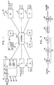
Fig. 1 is a block diagram that schematically illustrates a service-enabled router, in accordance with an embodiment of the present invention; -
Fig. 2 is a flow chart that schematically illustrates feature chains applied to packets processed by a router, in accordance with an embodiment of the present invention; and -
Fig. 3 is a flow chart that schematically illustrates a method for defining and implementing feature failure policies, in accordance with an embodiment of the present invention. -
Fig. 1 , is a block diagram that schematically illustrates a service-enabledrouter 20, in accordance with an embodiment of the present invention. The router comprisesmultiple line cards 22, each having one ormore interfaces 24 for connecting to communication lines. The line cards are interconnected via a switching core, which typically has the form of aswitch fabric 26. The router may also comprises one ormore service cards 28, also connected tofabric 26, for applying certain services to data packets processed by the router, as described hereinbelow. - Typically, packets are received in
line cards 22 by a Layer 1 (physical layer)processor 30 and are then processed by a Layer 2 (medium access control [MAC])processor 32 and a Layer 3 (network layer)processor 34, as are known in the art. Optionally, a giveninterface 24 may serve multiple virtual sub-interfaces 36, such as Virtual Local Area Networks (VLANs). As another option, the interface may be a virtual interface, such as a tunnel interface, which is not related to a particular physical interface. Layer 3processor 34 may serve as a service processor, to apply additional service features to each packet. (Alternatively,line card 22 may comprise a separate service processor, not shown in the figure, for this purpose.) Exemplary features shown inFig 1 include an ACL (Access Control List) filter 40 and aQoS controller 42. After applying the appropriate services to the packet, the ingress line card passes the packet tofabric 26. - In some cases, packets may be subject to additional processing features that are performed on
service cards 28, rather thanline cards 22. For example, in the configuration shown inFig. 1 , some (or all) packets are passed byfabric 26 to afirewall 46 onservice card 28. This firewall is implemented by aservice processor 44 on the service card. -
Fabric 26 then passes the packets to the appropriate egress line card, which may apply additional processing features to the packets before transmitting them onward via one ofinterfaces 24. - The structure of
router 20 inFig. 1 and the order of processing operations in the figure are shown here solely by way of example, to illustrate one possible implementation of the principles of the present invention. Alternative router and service feature configurations will be apparent to those skilled in the art and are considered to be within the scope of the present invention. The functional blocks identified within the router are presented for the sake of conceptual clarity and do not necessarily reflect the actual hardware or software structure of the router. Rather, the functions of an individual block that is shown in the figure may be divided among multiple physical blocks in an actual implementation of the router or, conversely, a number of different blocks may be combined into the functions of a single processor. The elements ofrouter 20 may be implemented using dedicated or programmable hardware elements or, alternatively, in software running on an embedded microprocessor or computing platform. This software may be downloaded to the router in electronic form, over a network, for example, or it may alternatively be provided on tangible media, such as optical, magnetic, or electronic memory media. -
Fig. 2 is a flow chart that schematically illustrates processing features applied to packets transferred throughrouter 20, in accordance with an embodiment of the present invention. The features are arranged in aningress feature chain 50 and anegress feature chain 52. Both the ingress and egress feature chains may be defined individually for each ingress interface (or sub-interface) and egress interface (or sub-interface) in the router. Thus, the operator ofrouter 20 may provide different sets of features to different users, who are connected to different, respective interfaces of the router. The order of features may also be varied from one interface to another. Furthermore, for a given interface, different feature chains may be defined for different traffic directions (ingress or egress). - In the example shown in
Fig. 2 ,ingress feature chain 50 comprises aningress ACL filter 54, aQoS controller 56, and afirewall 58. (The ACL filter is a collection of permit and deny conditions that apply to IP addresses of incoming packets.) Packets that successfully pass through the ingress feature chain are forwarded by arouting process 60 to the egress path. In this case,egress chain 52 comprises only a single feature: anegress ACL filter 62. The features in the ingress and egress feature chains may be implemented either inline cards 22 or inservice cards 28, depending on the configuration and capabilities of the router. - Alternatively, different features and larger or smaller numbers of features may be defined in each of the ingress and egress feature chains. Representative features include those listed in the Background of the Invention above, as well as the following:
- o Aggregated or sampled netflow accounting
- o Policy-based routing (PBR)
- o BGP Policy Accounting (BGP-PA)
- oQoS Policy Propagation via BGP (QPPB)
- o Traffic redirection, such as Web cache redirect (WCCP)
- o Lawful Interception (LI)
- o Network address translation (NAT/PAT)
- o Network-based application recognition (NBAR)
- o Voice Session Border Control (S/BC)
- oServer load balancing.
- Other applicable features will be apparent to those skilled in the art and are considered to be within the scope of the present invention.
- In many cases,
router 20 is configured with redundant components, so that service features can be maintained even if the component running a particular feature fails. In some cases, however, there may be no backup available. For example, multiple failures may occur concurrently, or the service provider operating the router may have chosen to reduce cost by reducing (or eliminating) redundancy. In such events,router 20 applies a predetermined failure policy in deciding how to respond to the failure. Embodiments of the present invention permit the failure policy to be configured and applied individually for eachinterface 24 or sub-interface 36 of the router and each feature on this interface, as described hereinbelow. -
Fig. 3 is a flow chart that schematically illustrates a method for defining and implementing failure policies inrouter 20, in accordance with an embodiment of the present invention. Feature chains are initially defined for each interface 24 (and possibly for some or all sub-interfaces 36) in the router, at afeature definition step 70. Additionally or alternatively, feature chains may be defined for certain traffic classes and/or specific protocols. These class- or protocol-specific feature chains may extend acrossmultiple interfaces 24 or across all the interfaces. - A failure policy is then defined for each feature (or feature type) in each feature chain, at a
failure definition step 72. In other words, the same feature appearing in feature chains of different interfaces or sub-interfaces may have a different associated failure policy in each chain. The failure policy may act on the whole feature chain, for example, by changing the interface state, altering the behavior of other service features in the chain, or adding and/or removing service features. - Exemplary failure policies include the following:
- A traffic dropping policy 73 - Traffic received on or destined for the interface in question is simply discarded in the event that the feature in question fails. This policy is equivalent to routing the traffic to a non-existent egress interface (which, for example, can lead to loss of unicast IPv4 traffic, without necessarily affecting IPv6, multicast, and other traffic types).
- A service bypass policy 74 - The failed feature is temporarily eliminated from the feature chain, so that packets are passed to the next feature along the chain.
- An interface shutdown policy 76 - Typically, Layer 1
processor 30 is shut down when the feature in question fails. In this case (in contrast to drop traffic policy 72), the router upstream of the interface in question will detect that the interface is down and will attempt to reroute packets through other interfaces or routers. This policy may not be desirable, for example, when different feature chains are assigned to different sub-interfaces of the same interface, since it will force all of the sub-interfaces to shut down. - A protocol shutdown policy 78 - Either Layer 2
processor 32 or Layer 3processor 34 is shut down. This policy can be applied per sub-interface. It can also be applied per protocol, so that a given Layer 3 protocol, such as IPv4, is blocked, while other Layer 3 protocols are permitted to pass, for example. - A feature chain change policy 80 - Typically, another feature is substituted for the failed feature. For example, upon failure of a firewall or other security measure implemented by one of service cards.28, a stringent ACL may be applied on the
line card 22 serving the interface in question. As another example, a failure of a voice-related service could cause activation of an ACL that blocks voice traffic. - A route cost change policy 82 - Layer 3
processor 34 may advertise a different (typically higher) cost for routing of packets through the interface in question, using routing protocols known in the art. As a result, other routers will seek to route traffic away from this interface. - The above policies are listed solely by way of example, and other policies may similarly be used.
- Once the feature chains and failure policies have been defined,
router 20 is operational and proceeds to route packets throughinterfaces 24, subject to the applicable services specified by the feature chains, at arouting step 84. Normal routing continues in this manner unless and until a failure event is detected in one of the service features, at afailure detection step 86. The appropriate processor in the router then determines whether there is a redundant backup component available to take the place of the failed feature, at a backupavailability checking step 88. If so, the backup component is activated, at abackup activation step 90. The interface (or interfaces) affected by the failure may then continue operation without change to the feature chain. - Alternatively, when it is determined at
step 88 that there is no available backup, the router implements the predefined failure policy, at apolicy invocation step 92. As a result, the failed service may be bypassed, the affected interface may be shut down, packets on the interface may be dropped, or other actions may be taken, such as those listed above. Upon recovery of the failed feature, operation of the affected interface typically returns to normal. - Although the embodiments above are described with reference to a router, i.e., a Layer 3 data switch, the principles of the present invention may similarly be applied in providing service features in data switches of other types, such as Layer 2 data switches. It will thus be appreciated that the embodiments described above are cited by way of example, and that the present invention is not limited to what has been particularly shown and described hereinabove. Rather, the scope of the present invention includes both combinations and subcombinations of the various features described hereinabove, as well as variations and modifications thereof which would occur to persons skilled in the art upon reading the foregoing description and which are not disclosed in the prior art.
Claims (19)
- A method for communication, comprising:associating respective feature chains with a plurality of interfaces (24) of a data switch (20), the feature chains comprising service features;defining (72) a respective failure policy for each of one or more of the service features in each of the feature chains;detecting (86) a failure in a service feature in a feature chain associated with one of the interfaces (24); androuting data packets through the data switch while applying (92), responsively to the failure, the respective failure policy to the one of the interfaces (24).
- The method according to claim 1, wherein the plurality of the interfaces (24) comprises at least first and second interfaces, and wherein associating the respective feature chains comprises respectively associating different first and second feature chains with the first and second interfaces (24).
- The method according to claim 1, wherein the plurality of the interfaces (24)comprises at least first and second interfaces, and wherein defining (72) the respective failure policy comprises defining different first and second failure policies for the service features in the feature chains associated with the first and second interfaces (24).
- The method according to claim 3, wherein the feature chains associated with the first and second interfaces (24) respectively comprise first and second feature chains, both comprising a common service feature, and
wherein defining (72) different first and second failure policies comprises assigning the first failure policy to the common service feature in the first feature chain and assigning the second failure policy to the common service feature in the second feature chain. - The method according to claim 1, wherein the service features are selected from a list comprising Quality of Service (QoS) features, virtual private network (VPN) features, security features, accounting features, statistics and billing features, netflow features, routing features, traffic redirection features, interception features, network address translation (NAT) features, application recognition features and load balancing features.
- The method according to any of claims 1-5, wherein defining (72) the respective failure policy comprises defining a traffic dropping policy or defining a service bypass policy or defining an interface shutdown policy or defining a protocol shutdown policy or defining a feature chain change policy, preferably wherein the feature chain comprises a firewall, and wherein the feature chain change policy comprises activating access control list (ACL) filtering responsively when the firewall fails or wherein defining the respective failure policy comprises defining a route cost change policy.
- The method according to any of claims 1-5, wherein applying (92) the respective failure policy comprises invoking a redundant component as a backup for the service failure when the redundant component is available, and applying the respective failure policy when there is no redundant component available.
- The method according to any of claims 1-5, wherein associating the respective feature chains comprises associating different respective feature chains with different sub-interfaces of a given interface, and wherein defining the respective failure policy comprises defining different respective failure policies for the service features in the feature chains associated with the different sub-interfaces.
- The method according to any of claims 1-5, wherein associating the respective feature chains comprises defining a class feature chain for application to a class of traffic across at least a subset of the plurality of interfaces (24).
- Apparatus for communication, comprising:means for associating respective feature chains with a plurality of interfaces (24) of a data switch (20), the feature chains comprising service features;means for defining a respective failure policy for each of one or more of the service features in each of the feature chains;means for detecting a failure in a service feature in a feature chain associated with one of the interfaces (24); andmeans for routing data packets through the data switch (20) while applying, responsively to the failure, the respective failure policy to the one of the interfaces (24).
- The apparatus according to claim 10, wherein the plurality of the interfaces (24) comprises at least first and second interfaces, and wherein the feature chains comprise different first and second feature chains that are respectively associated with the first and second interfaces (24).
- The apparatus according to claim 10, wherein the plurality of the interfaces (24) comprises at least first and second interfaces, and wherein said means for defining is arranged to define different first and second failure policies for the service features in the feature chains associated with the first and second interfaces (24), preferably wherein the feature chains associated with the first and second interfaces (24) respectively comprise first and second feature chains, both comprising a common service feature, and
wherein the first failure policy is assigned to the common service feature in the first feature chain and the second failure policy, different from the first failure policy, is assigned to the common service feature in the second feature chain. - The apparatus according to claim 10, wherein the service features are selected from a list comprising Quality of Service (QoS) features, virtual private network (VPN) features, security features, accounting features, statistics and billing features, netflow features, routing features, traffic redirection features, interception features, network address translation (NAT) features, application recognition features and load balancing features.
- The apparatus according to any of claims 10-13, wherein the failure policy comprises a traffic dropping policy or wherein the failure policy comprises a service bypass policy or wherein the failure policy comprises an interface shutdown policy or wherein the failure policy comprises a protocol shutdown policy or wherein the failure policy comprises a feature chain change policy or wherein the failure policy comprises a route cost change policy.
- The apparatus according to any of claims 10-14, comprising at least one service processor that is arranged to invoke a redundant component as a backup for the service failure when the redundant component is available, and to apply the respective failure policy when there is no redundant component available.
- The apparatus according to any of claims 10-15, wherein one or more of the interfaces (24) is configured to support multiple sub-interfaces, and wherein the means for associating is arranged to associate different respective feature chains with different, sub-interfaces of a given interface (24), and to accept a definition of different respective failure policies for the service features in the feature chains associated with the different sub-interfaces.
- The apparatus according to any of claims 10-16, comprising means for applying a class feature chain to a class of traffic across at least a subset of the plurality of interfaces (24).
- A method for communication, comprising:associating respective feature chains with a plurality of classes of traffic processed by a data switch (20), the feature chains comprising service features;defining a respective failure policy for each of one or more of the service features in each of the feature chains;detecting a failure in a service feature in a feature chain associated with one of the classes of traffic; androuting data packets through the data switch (20) while applying, responsively to the failure, the respective failure policy to the one of the classes of traffic.
- An apparatus for communication, comprising:means for associating respective feature chains with a plurality of classes of traffic processed by a data switch (20), the feature chains comprising service features;means for defining a respective failure policy for each of one or more of the service features in each of the feature chains;means for detecting a failure in a service feature in a feature chain associated with one of the classes of traffic; andmeans for routing data packets through the data switch (20) while applying, responsively to the failure, the respective failure policy to the one of the classes of traffic.
Applications Claiming Priority (2)
| Application Number | Priority Date | Filing Date | Title |
|---|---|---|---|
| US11/409,475 US7877505B1 (en) | 2006-04-21 | 2006-04-21 | Configurable resolution policy for data switch feature failures |
| PCT/IL2006/001429 WO2007122603A2 (en) | 2006-04-21 | 2006-12-12 | Configurable resolution policy for data switch feature failures |
Publications (3)
| Publication Number | Publication Date |
|---|---|
| EP2014018A2 EP2014018A2 (en) | 2009-01-14 |
| EP2014018A4 EP2014018A4 (en) | 2010-06-09 |
| EP2014018B1 true EP2014018B1 (en) | 2011-08-03 |
Family
ID=38625406
Family Applications (1)
| Application Number | Title | Priority Date | Filing Date |
|---|---|---|---|
| EP06832231A Active EP2014018B1 (en) | 2006-04-21 | 2006-12-12 | Configurable resolution policy for data switch feature failures |
Country Status (5)
| Country | Link |
|---|---|
| US (1) | US7877505B1 (en) |
| EP (1) | EP2014018B1 (en) |
| CN (1) | CN101496365B (en) |
| AT (1) | ATE519299T1 (en) |
| WO (1) | WO2007122603A2 (en) |
Families Citing this family (4)
| Publication number | Priority date | Publication date | Assignee | Title |
|---|---|---|---|---|
| US8630287B2 (en) * | 2010-08-20 | 2014-01-14 | Marvell Israel (M.I.S.L) Ltd. | Multiple core network device with core redundancy |
| US20130332596A1 (en) * | 2012-06-11 | 2013-12-12 | James O. Jones | Network traffic tracking |
| EP2808846A1 (en) * | 2013-05-31 | 2014-12-03 | Cabeco AB | Device and method for detecting faults in electronic systems |
| CN104735047B (en) * | 2014-12-02 | 2018-04-27 | 重庆晴彩科技有限公司 | A kind of hybrid-mode network physical link is met an urgent need intelligent switching system |
Family Cites Families (18)
| Publication number | Priority date | Publication date | Assignee | Title |
|---|---|---|---|---|
| US5260945A (en) | 1989-06-22 | 1993-11-09 | Digital Equipment Corporation | Intermittent component failure manager and method for minimizing disruption of distributed computer system |
| US6029197A (en) | 1997-02-14 | 2000-02-22 | Advanced Micro Devices, Inc. | Management information base (MIB) report interface for abbreviated MIB data |
| US6078953A (en) * | 1997-12-29 | 2000-06-20 | Ukiah Software, Inc. | System and method for monitoring quality of service over network |
| CN1328885C (en) | 1999-02-23 | 2007-07-25 | 阿尔卡塔尔互联网运行公司 | Multibusiness network exchanger having cut-in quality |
| US7222147B1 (en) * | 2000-05-20 | 2007-05-22 | Ciena Corporation | Processing network management data in accordance with metadata files |
| US7349960B1 (en) * | 2000-05-20 | 2008-03-25 | Ciena Corporation | Throttling distributed statistical data retrieval in a network device |
| US6973229B1 (en) * | 2001-02-28 | 2005-12-06 | Lambda Opticalsystems Corporation | Node architecture for modularized and reconfigurable optical networks, and methods and apparatus therefor |
| US20020184487A1 (en) * | 2001-03-23 | 2002-12-05 | Badamo Michael J. | System and method for distributing security processing functions for network applications |
| US7269157B2 (en) | 2001-04-10 | 2007-09-11 | Internap Network Services Corporation | System and method to assure network service levels with intelligent routing |
| WO2003003210A2 (en) | 2001-06-27 | 2003-01-09 | Arbor Networks | Method and system for monitoring control signal traffic over a computer network |
| CN1414757A (en) * | 2002-05-08 | 2003-04-30 | 华为技术有限公司 | Method of automatic sequential arranging access control list rule and its application |
| US6947375B2 (en) | 2003-01-27 | 2005-09-20 | Nokia Inc. | System and method for network card switchovers in an IP network |
| CN1319326C (en) * | 2003-04-01 | 2007-05-30 | 华为技术有限公司 | Band width statistical multiplex method based on acknowledged cut in speed |
| CN1728679A (en) * | 2004-07-31 | 2006-02-01 | 华为技术有限公司 | Method for configuring routers |
| US7606147B2 (en) * | 2005-04-13 | 2009-10-20 | Zeugma Systems Inc. | Application aware traffic shaping service node positioned between the access and core networks |
| US8151339B2 (en) * | 2005-12-23 | 2012-04-03 | Avaya, Inc. | Method and apparatus for implementing filter rules in a network element |
| US8340088B2 (en) * | 2008-09-11 | 2012-12-25 | Juniper Networks, Inc. | Methods and apparatus related to a low cost data center architecture |
| US8730954B2 (en) * | 2008-09-11 | 2014-05-20 | Juniper Networks, Inc. | Methods and apparatus related to any-to-any connectivity within a data center |
-
2006
- 2006-04-21 US US11/409,475 patent/US7877505B1/en not_active Expired - Fee Related
- 2006-12-12 WO PCT/IL2006/001429 patent/WO2007122603A2/en active Application Filing
- 2006-12-12 AT AT06832231T patent/ATE519299T1/en not_active IP Right Cessation
- 2006-12-12 EP EP06832231A patent/EP2014018B1/en active Active
- 2006-12-12 CN CN2006800542988A patent/CN101496365B/en active Active
Also Published As
| Publication number | Publication date |
|---|---|
| EP2014018A4 (en) | 2010-06-09 |
| WO2007122603A2 (en) | 2007-11-01 |
| WO2007122603A3 (en) | 2009-04-16 |
| CN101496365A (en) | 2009-07-29 |
| ATE519299T1 (en) | 2011-08-15 |
| US7877505B1 (en) | 2011-01-25 |
| EP2014018A2 (en) | 2009-01-14 |
| CN101496365B (en) | 2013-08-28 |
Similar Documents
| Publication | Publication Date | Title |
|---|---|---|
| EP1690403B1 (en) | Dual mode firewall | |
| US10084751B2 (en) | Load balancing among a cluster of firewall security devices | |
| US7224668B1 (en) | Control plane security and traffic flow management | |
| US9270639B2 (en) | Load balancing among a cluster of firewall security devices | |
| JP4886788B2 (en) | Virtual network, data network system, computer program, and method of operating computer program | |
| US7941837B1 (en) | Layer two firewall with active-active high availability support | |
| EP3605968B1 (en) | N:1 stateful application gateway redundancy model | |
| US20040131059A1 (en) | Single-pass packet scan | |
| US20040148520A1 (en) | Mitigating denial of service attacks | |
| US8479275B1 (en) | Secure high-throughput data-center network employing routed firewalls | |
| WO2003015374A1 (en) | Controlled information flow between communities via a firewall | |
| EP2014018B1 (en) | Configurable resolution policy for data switch feature failures | |
| CN110071905B (en) | Method for providing a connection, border network and IP server | |
| Cisco | Configuring Unicast Reverse Path Forwarding | |
| Cisco | Configuring IP Services | |
| Cisco | Release Notes for the Cisco 3600 Series for Cisco IOS Release 11.2 P | |
| Cisco | Release Notes for the Cisco 3600 Series for Cisco IOS Release 11.2 P | |
| Vadivelu et al. | Design and performance analysis of complex switching networks through VLAN, HSRP and link aggregation | |
| CN116170389B (en) | Service container drainage method, system and computer cluster | |
| US20050086524A1 (en) | Systems and methods for providing network security with zero network footprint | |
| Abrar et al. | Reliability and Load Handling Problem in Internet Service Provider’s Network | |
| Works | Unicast Reverse Path Forwarding |
Legal Events
| Date | Code | Title | Description |
|---|---|---|---|
| PUAI | Public reference made under article 153(3) epc to a published international application that has entered the european phase |
Free format text: ORIGINAL CODE: 0009012 |
|
| 17P | Request for examination filed |
Effective date: 20081118 |
|
| AK | Designated contracting states |
Kind code of ref document: A2 Designated state(s): AT BE BG CH CY CZ DE DK EE ES FI FR GB GR HU IE IS IT LI LT LU LV MC NL PL PT RO SE SI SK TR |
|
| AX | Request for extension of the european patent |
Extension state: AL BA HR MK RS |
|
| RIN1 | Information on inventor provided before grant (corrected) |
Inventor name: CHATTERJEE, SIMON Inventor name: OZ, DORON Inventor name: ALTSHULER, SAREL |
|
| R17D | Deferred search report published (corrected) |
Effective date: 20090416 |
|
| RIC1 | Information provided on ipc code assigned before grant |
Ipc: H04L 12/66 20060101AFI20090422BHEP |
|
| A4 | Supplementary search report drawn up and despatched |
Effective date: 20100511 |
|
| RIC1 | Information provided on ipc code assigned before grant |
Ipc: H04L 12/56 20060101AFI20100505BHEP |
|
| GRAP | Despatch of communication of intention to grant a patent |
Free format text: ORIGINAL CODE: EPIDOSNIGR1 |
|
| RIC1 | Information provided on ipc code assigned before grant |
Ipc: H04L 12/56 20060101AFI20110117BHEP |
|
| GRAS | Grant fee paid |
Free format text: ORIGINAL CODE: EPIDOSNIGR3 |
|
| GRAA | (expected) grant |
Free format text: ORIGINAL CODE: 0009210 |
|
| AK | Designated contracting states |
Kind code of ref document: B1 Designated state(s): AT BE BG CH CY CZ DE DK EE ES FI FR GB GR HU IE IS IT LI LT LU LV MC NL PL PT RO SE SI SK TR |
|
| REG | Reference to a national code |
Ref country code: GB Ref legal event code: FG4D |
|
| REG | Reference to a national code |
Ref country code: CH Ref legal event code: EP |
|
| REG | Reference to a national code |
Ref country code: IE Ref legal event code: FG4D |
|
| REG | Reference to a national code |
Ref country code: DE Ref legal event code: R096 Ref document number: 602006023566 Country of ref document: DE Effective date: 20111006 |
|
| REG | Reference to a national code |
Ref country code: NL Ref legal event code: VDEP Effective date: 20110803 |
|
| LTIE | Lt: invalidation of european patent or patent extension |
Effective date: 20110803 |
|
| PG25 | Lapsed in a contracting state [announced via postgrant information from national office to epo] |
Ref country code: SE Free format text: LAPSE BECAUSE OF FAILURE TO SUBMIT A TRANSLATION OF THE DESCRIPTION OR TO PAY THE FEE WITHIN THE PRESCRIBED TIME-LIMIT Effective date: 20110803 Ref country code: IS Free format text: LAPSE BECAUSE OF FAILURE TO SUBMIT A TRANSLATION OF THE DESCRIPTION OR TO PAY THE FEE WITHIN THE PRESCRIBED TIME-LIMIT Effective date: 20111203 Ref country code: FI Free format text: LAPSE BECAUSE OF FAILURE TO SUBMIT A TRANSLATION OF THE DESCRIPTION OR TO PAY THE FEE WITHIN THE PRESCRIBED TIME-LIMIT Effective date: 20110803 Ref country code: LT Free format text: LAPSE BECAUSE OF FAILURE TO SUBMIT A TRANSLATION OF THE DESCRIPTION OR TO PAY THE FEE WITHIN THE PRESCRIBED TIME-LIMIT Effective date: 20110803 Ref country code: PT Free format text: LAPSE BECAUSE OF FAILURE TO SUBMIT A TRANSLATION OF THE DESCRIPTION OR TO PAY THE FEE WITHIN THE PRESCRIBED TIME-LIMIT Effective date: 20111205 Ref country code: NL Free format text: LAPSE BECAUSE OF FAILURE TO SUBMIT A TRANSLATION OF THE DESCRIPTION OR TO PAY THE FEE WITHIN THE PRESCRIBED TIME-LIMIT Effective date: 20110803 |
|
| REG | Reference to a national code |
Ref country code: AT Ref legal event code: MK05 Ref document number: 519299 Country of ref document: AT Kind code of ref document: T Effective date: 20110803 |
|
| PG25 | Lapsed in a contracting state [announced via postgrant information from national office to epo] |
Ref country code: PL Free format text: LAPSE BECAUSE OF FAILURE TO SUBMIT A TRANSLATION OF THE DESCRIPTION OR TO PAY THE FEE WITHIN THE PRESCRIBED TIME-LIMIT Effective date: 20110803 Ref country code: LV Free format text: LAPSE BECAUSE OF FAILURE TO SUBMIT A TRANSLATION OF THE DESCRIPTION OR TO PAY THE FEE WITHIN THE PRESCRIBED TIME-LIMIT Effective date: 20110803 Ref country code: GR Free format text: LAPSE BECAUSE OF FAILURE TO SUBMIT A TRANSLATION OF THE DESCRIPTION OR TO PAY THE FEE WITHIN THE PRESCRIBED TIME-LIMIT Effective date: 20111104 Ref country code: AT Free format text: LAPSE BECAUSE OF FAILURE TO SUBMIT A TRANSLATION OF THE DESCRIPTION OR TO PAY THE FEE WITHIN THE PRESCRIBED TIME-LIMIT Effective date: 20110803 Ref country code: CY Free format text: LAPSE BECAUSE OF FAILURE TO SUBMIT A TRANSLATION OF THE DESCRIPTION OR TO PAY THE FEE WITHIN THE PRESCRIBED TIME-LIMIT Effective date: 20110803 Ref country code: SI Free format text: LAPSE BECAUSE OF FAILURE TO SUBMIT A TRANSLATION OF THE DESCRIPTION OR TO PAY THE FEE WITHIN THE PRESCRIBED TIME-LIMIT Effective date: 20110803 |
|
| PG25 | Lapsed in a contracting state [announced via postgrant information from national office to epo] |
Ref country code: BE Free format text: LAPSE BECAUSE OF FAILURE TO SUBMIT A TRANSLATION OF THE DESCRIPTION OR TO PAY THE FEE WITHIN THE PRESCRIBED TIME-LIMIT Effective date: 20110803 |
|
| PG25 | Lapsed in a contracting state [announced via postgrant information from national office to epo] |
Ref country code: CZ Free format text: LAPSE BECAUSE OF FAILURE TO SUBMIT A TRANSLATION OF THE DESCRIPTION OR TO PAY THE FEE WITHIN THE PRESCRIBED TIME-LIMIT Effective date: 20110803 Ref country code: SK Free format text: LAPSE BECAUSE OF FAILURE TO SUBMIT A TRANSLATION OF THE DESCRIPTION OR TO PAY THE FEE WITHIN THE PRESCRIBED TIME-LIMIT Effective date: 20110803 |
|
| PG25 | Lapsed in a contracting state [announced via postgrant information from national office to epo] |
Ref country code: EE Free format text: LAPSE BECAUSE OF FAILURE TO SUBMIT A TRANSLATION OF THE DESCRIPTION OR TO PAY THE FEE WITHIN THE PRESCRIBED TIME-LIMIT Effective date: 20110803 Ref country code: IT Free format text: LAPSE BECAUSE OF FAILURE TO SUBMIT A TRANSLATION OF THE DESCRIPTION OR TO PAY THE FEE WITHIN THE PRESCRIBED TIME-LIMIT Effective date: 20110803 Ref country code: RO Free format text: LAPSE BECAUSE OF FAILURE TO SUBMIT A TRANSLATION OF THE DESCRIPTION OR TO PAY THE FEE WITHIN THE PRESCRIBED TIME-LIMIT Effective date: 20110803 |
|
| PLBE | No opposition filed within time limit |
Free format text: ORIGINAL CODE: 0009261 |
|
| STAA | Information on the status of an ep patent application or granted ep patent |
Free format text: STATUS: NO OPPOSITION FILED WITHIN TIME LIMIT |
|
| PG25 | Lapsed in a contracting state [announced via postgrant information from national office to epo] |
Ref country code: DK Free format text: LAPSE BECAUSE OF FAILURE TO SUBMIT A TRANSLATION OF THE DESCRIPTION OR TO PAY THE FEE WITHIN THE PRESCRIBED TIME-LIMIT Effective date: 20110803 |
|
| 26N | No opposition filed |
Effective date: 20120504 |
|
| PG25 | Lapsed in a contracting state [announced via postgrant information from national office to epo] |
Ref country code: MC Free format text: LAPSE BECAUSE OF NON-PAYMENT OF DUE FEES Effective date: 20111231 |
|
| REG | Reference to a national code |
Ref country code: CH Ref legal event code: PL |
|
| REG | Reference to a national code |
Ref country code: DE Ref legal event code: R097 Ref document number: 602006023566 Country of ref document: DE Effective date: 20120504 |
|
| REG | Reference to a national code |
Ref country code: IE Ref legal event code: MM4A |
|
| PG25 | Lapsed in a contracting state [announced via postgrant information from national office to epo] |
Ref country code: LI Free format text: LAPSE BECAUSE OF NON-PAYMENT OF DUE FEES Effective date: 20111231 Ref country code: CH Free format text: LAPSE BECAUSE OF NON-PAYMENT OF DUE FEES Effective date: 20111231 Ref country code: IE Free format text: LAPSE BECAUSE OF NON-PAYMENT OF DUE FEES Effective date: 20111212 |
|
| PG25 | Lapsed in a contracting state [announced via postgrant information from national office to epo] |
Ref country code: ES Free format text: LAPSE BECAUSE OF FAILURE TO SUBMIT A TRANSLATION OF THE DESCRIPTION OR TO PAY THE FEE WITHIN THE PRESCRIBED TIME-LIMIT Effective date: 20111114 |
|
| PG25 | Lapsed in a contracting state [announced via postgrant information from national office to epo] |
Ref country code: LU Free format text: LAPSE BECAUSE OF NON-PAYMENT OF DUE FEES Effective date: 20111212 |
|
| PG25 | Lapsed in a contracting state [announced via postgrant information from national office to epo] |
Ref country code: BG Free format text: LAPSE BECAUSE OF FAILURE TO SUBMIT A TRANSLATION OF THE DESCRIPTION OR TO PAY THE FEE WITHIN THE PRESCRIBED TIME-LIMIT Effective date: 20111103 |
|
| PG25 | Lapsed in a contracting state [announced via postgrant information from national office to epo] |
Ref country code: TR Free format text: LAPSE BECAUSE OF FAILURE TO SUBMIT A TRANSLATION OF THE DESCRIPTION OR TO PAY THE FEE WITHIN THE PRESCRIBED TIME-LIMIT Effective date: 20110803 |
|
| PG25 | Lapsed in a contracting state [announced via postgrant information from national office to epo] |
Ref country code: HU Free format text: LAPSE BECAUSE OF FAILURE TO SUBMIT A TRANSLATION OF THE DESCRIPTION OR TO PAY THE FEE WITHIN THE PRESCRIBED TIME-LIMIT Effective date: 20110803 |
|
| REG | Reference to a national code |
Ref country code: FR Ref legal event code: PLFP Year of fee payment: 10 |
|
| REG | Reference to a national code |
Ref country code: FR Ref legal event code: PLFP Year of fee payment: 11 |
|
| REG | Reference to a national code |
Ref country code: FR Ref legal event code: PLFP Year of fee payment: 12 |
|
| P01 | Opt-out of the competence of the unified patent court (upc) registered |
Effective date: 20230525 |
|
| PGFP | Annual fee paid to national office [announced via postgrant information from national office to epo] |
Ref country code: GB Payment date: 20231222 Year of fee payment: 18 |
|
| PGFP | Annual fee paid to national office [announced via postgrant information from national office to epo] |
Ref country code: FR Payment date: 20231226 Year of fee payment: 18 Ref country code: DE Payment date: 20231212 Year of fee payment: 18 |