JP2005190834A - Luminaire with protective tube - Google Patents
Luminaire with protective tube Download PDFInfo
- Publication number
- JP2005190834A JP2005190834A JP2003430851A JP2003430851A JP2005190834A JP 2005190834 A JP2005190834 A JP 2005190834A JP 2003430851 A JP2003430851 A JP 2003430851A JP 2003430851 A JP2003430851 A JP 2003430851A JP 2005190834 A JP2005190834 A JP 2005190834A
- Authority
- JP
- Japan
- Prior art keywords
- tube
- protective tube
- flank
- inclination angle
- angle
- Prior art date
- Legal status (The legal status is an assumption and is not a legal conclusion. Google has not performed a legal analysis and makes no representation as to the accuracy of the status listed.)
- Pending
Links
Images

Landscapes
- Non-Portable Lighting Devices Or Systems Thereof (AREA)
Abstract
【課題】 ルーバーまたは光案内プレートを追加して用いなくても、十分な光を好ましい方向に案内するように、保護チューブ付き照明器具を得ること。
【解決手段】透明な材料製であって光を案内するフレネル構造のみぞを表面に備える円筒形チューブを備え、チューブ内部にランプを同軸に配置する上記の保護チューブつき照明器具において、複数のみぞが軸に平行に設けられ、これらのみぞはチューブの光を射出する側かつ軸方向に直径を切断する平面より下に配置され、その際これらのみぞの作用フランクと妨害フランクの向きは、ランプから生じた光線が事前指定かつ限定された射出角において方向変換されるような向きとすることを特徴とする。
【選択図】 図2
PROBLEM TO BE SOLVED: To obtain a lighting fixture with a protective tube so as to guide sufficient light in a preferable direction without using a louver or a light guide plate.
A lighting device with a protective tube comprising a cylindrical tube made of a transparent material and having a Fresnel structure groove for guiding light on a surface thereof, and a lamp arranged coaxially inside the tube. Are arranged parallel to the axis, and these grooves are arranged on the side of the tube where the light is emitted and below the plane that cuts the diameter in the axial direction. The direction of the light beam generated from is changed in direction at a pre-specified and limited exit angle.
[Selection] Figure 2
Description
本発明は請求項1の上位概念に記載する種類の保護チューブ付き照明器具に関する。
The invention relates to a luminaire with a protective tube of the kind described in the superordinate concept of
この種の保護チューブ付き照明器具は主として、透明な材料例えばプラスチックまたは天然素材ガラス製の円筒形チューブを備え、そのチューブの中に、照明手段としてランプ好ましくは蛍光ランプを同軸に配置する。
この保護チューブ付き照明器具は、好ましくは湿潤なあるいは水中の環境で用いられる。この照明装置は、簡単な手段によって水密な仕様とすることができるからである。
この保護チューブ付き照明器具は、例えば野外、湿潤な空間、あるいは水中における照明目的に適している。
しかしその構造が簡単かつコンパクトであるため、この保護チューブ付き照明器具にグレア防止または光の案内のための水密な手段を設ける場合、問題がないわけではない。
この種の保護チューブ付き照明器具内部に、この照明器具チューブの内側輪郭に適合されたグレア防止ルーバーを設けることが知られている(例えば、特許文献1)。この種の解決法は比較的手間がかかり、特に十分な断面積を持つ照明器具チューブを必要とする。
This luminaire with protective tube is preferably used in a wet or underwater environment. This is because the lighting device can be made watertight by simple means.
This luminaire with a protective tube is suitable, for example, for illumination purposes in the outdoors, in humid spaces or underwater.
However, since the structure is simple and compact, it is not without problems if this lighting fixture with a protective tube is provided with watertight means for glare prevention or light guidance.
It is known that an antiglare louver adapted to the inner contour of the luminaire tube is provided inside the luminaire with a protective tube of this type (for example, Patent Document 1). This type of solution is relatively laborious and requires a luminaire tube with a particularly sufficient cross-sectional area.
さらにこれと同等の種類のものとして、蛍光ランプを透明なプラスチック形材で包み、この形材に長手方向に複数のみぞをつけ、これにより長手方向にそってグレア防止を施すものが知られている。
しかしこれは防湿された保護チューブ付き照明器具ではない。そればかりかこのみぞ付き形材は、光の案内のために用いられるのではなく、長手方向にグレア防止を施すのに用いられるとしても、それは全反射の利用によるだけである。
また、円周方向に伸びるフレネル構造のみぞを外側表面に備える透明な円筒が知られている(例えば、特許文献2)。このフレネルみぞは希望された光の案内に用いられる。この場合光源として、大小の差はあれともかくポイント状の光源として放射する白熱ランプが備えられる。
But this is not a dampproof luminaire with a protective tube. Not only that, but this grooved profile is used not only for guiding light, but also for preventing glare in the longitudinal direction, it is only due to the use of total internal reflection.
Further, a transparent cylinder having a fresnel structure groove extending in the circumferential direction on its outer surface is known (for example, Patent Document 2). This Fresnel groove is used to guide the desired light. In this case, an incandescent lamp that radiates as a point-like light source is provided as a light source regardless of the size.
本発明の課題は、ルーバーまたは光案内プレートを追加して用いなくても、十分な光を好ましい方向に案内するように、保護チューブ自体が構成されているような、保護チューブ付き照明器具を得ることである。 The object of the present invention is to obtain a luminaire with a protective tube in which the protective tube itself is configured to guide sufficient light in a preferred direction without the use of additional louvers or light guide plates. That is.
本発明は上記の課題の解決法として、軸に平行に伸びるフレネル構造のみぞをその円筒形チューブに設け、チューブの光射出側に、かつチューブの軸にそってその直径を切った面より下に、そのみぞを配置することを提案する。求められる光の案内を達成するため、本発明のもう1つの特徴として、みぞの作用フランクと妨害フランクの向きは、ランプから生じた光線が、事前指定かつ限定された光射出角で方向変換されるような向きとする。
円筒形チューブの光学的に透明な断面構造は、一方では求められる光案内の作用を行い、他方では照明軸を横切って位置する平面において、最大の視角でグレア輝度を減少させる。
特に有利な光の集束が得られるのは、請求項2に記載する通り、作用フランク法線のそれに付随する中心光線に対する傾斜角度が、中心光線のグローバル角度に依存して、0〜90°の間で増加する場合である。このグローバル角度とは、軸にそって直径を切った面の法線に対する中心光線の角度と定義する。
The present invention provides a solution to the above problem by providing a groove in the cylindrical tube with a Fresnel structure extending parallel to the axis, on the light exit side of the tube, and below the diameter cut surface along the axis of the tube. Propose to arrange the groove. In order to achieve the required light guidance, another feature of the present invention is that the orientation of the groove working flank and jamming flank is such that the light rays originating from the lamp are redirected at a pre-specified and limited light exit angle. The direction is as follows.
The optically transparent cross-sectional structure of the cylindrical tube provides the required light guiding action on the one hand and reduces glare brightness at the maximum viewing angle on the other hand on the plane located across the illumination axis.
Particularly advantageous light focusing is obtained, as claimed in claim 2, in which the tilt angle of the working flank normal with respect to its associated central ray is between 0 and 90 °, depending on the global angle of the central ray. It is a case where it increases between. This global angle is defined as the angle of the central ray with respect to the normal of the surface cut along the axis.
請求項3に記載する通り、妨害フランクと中心光線がなす角度は、中心光線のグローバル角度に依存して増加するものとするのが合目的であろう。
みぞの構造は請求項4に記載する通り、円筒形チューブ被覆の内側表面に設けることができる。この場合、作用フランク法線の傾斜角度を計算するため、請求項10に挙げた法則が得られる。
チューブ中心の理想的な線光源の中心光線に対する妨害フランクの傾斜角度を計算するため、請求項12に挙げた法則が得られる。
同様に円筒形チューブ被覆の外側表面にもみぞ構造を設けることができる。これを請求項5が提案する。
この場合、作用フランク法線の中心光線に対する傾斜角度について請求項11に挙げた計算法則が適用される。中心光線に対する妨害フランクの傾斜角度については、この場合請求項13に挙げた法則が得られる。
As claimed in claim 3, it may be expedient for the angle between the disturbing flank and the central ray to increase depending on the global angle of the central ray.
The groove structure can be provided on the inner surface of the cylindrical tube covering as described in claim 4. In this case, in order to calculate the inclination angle of the acting flank normal, the law recited in
In order to calculate the inclination angle of the disturbing flank with respect to the central ray of the ideal line light source at the center of the tube, the law recited in claim 12 is obtained.
Similarly, a groove structure can be provided on the outer surface of the cylindrical tube covering. Claim 5 proposes this.
In this case, the calculation law recited in claim 11 is applied to the inclination angle of the action flank normal to the central ray. With respect to the inclination angle of the disturbing flank with respect to the central ray, in this case, the law recited in claim 13 is obtained.
この提案の技術的応用のためには、基本的に2つの方法がある。
請求項6に記載する通りこれらのみぞは、円筒形チューブの材料に直接に刻むことができる。すなわち円筒形チューブを製造するときに設けることができる。
しかし請求項7の提案に記載する通り、これらのみぞを透明なフィルムに刻んで、このフィルムを円筒形チューブに挿入、あるいは円筒形チューブ外側に取り付けることもできる。
There are basically two methods for the technical application of this proposal.
As described in claim 6, these grooves can be cut directly into the material of the cylindrical tube. That is, it can be provided when manufacturing a cylindrical tube.
However, as described in the proposal of claim 7, it is also possible to cut these grooves into a transparent film and insert this film into the cylindrical tube or attach it to the outside of the cylindrical tube.
請求項8に記載する通り、その円筒形チューブが天然材料のガラス、すなわち鉱物性ガラスからなる、あるいはプラスチック、すなわちアクリルガラスからなる保護チューブ付き照明器具によって、本発明を実現することができる。
請求項9に記載する通り、ランプとしては蛍光ランプが好ましい。しかし基本的には長い形の白熱ランプ、あるいはその他の例えば線形の照明手段を用いることができる。
As described in
As described in claim 9, the lamp is preferably a fluorescent lamp. Basically, however, a long incandescent lamp or other linear illumination means can be used.
下記に図面を用いて本発明の提案を具体的に説明する。
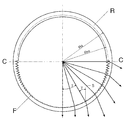
図1は、保護チューブ付き照明器具の光度分布を示す。この照明装置は、フレネル構造のみぞを持つ本発明の照明器具チューブを備える。
このチューブ付き照明装置は、理想的な形態として断面が円形の表面Lを持つものが示されている。
この光線の分布は、照明装置Lから生じた光が、照明装置長手軸に垂直な平面で、約45°の角度で主として下方に放射されることを明らかにする。
従ってこの照明装置は主方向Aにおいて最大光度を持つが、方向Bにおいては光度とそれとともにグレア輝度も著しく減少する。
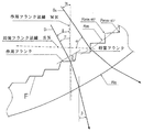
この効果は照明器具チューブRによって得られ、このチューブの断面を図2に示す。
チューブRの内面は、軸方向に直径を切った断面C‐Cの下に鋸歯状のみぞFを備えるが、これらのみぞの並び方を図3でさらに詳しく説明する。
これらのみぞは、図2に示すような射出された光の光路を生じる。
The proposal of the present invention will be specifically described below with reference to the drawings.
FIG. 1 shows the luminous intensity distribution of a luminaire with a protective tube. This illuminating device comprises the luminaire tube of the present invention having a fresnel structure groove.
This tube-equipped lighting device has an ideal form having a surface L with a circular cross section.
This distribution of rays reveals that the light originating from the illuminator L is emitted mainly downwards at an angle of about 45 ° in a plane perpendicular to the illuminator longitudinal axis.
Therefore, this illuminating device has the maximum luminous intensity in the main direction A, but in the direction B, the luminous intensity and the glare luminance are significantly reduced.
This effect is obtained by the luminaire tube R, the cross section of which is shown in FIG.
The inner surface of the tube R is provided with serrated grooves F under a cross section CC cut in diameter in the axial direction. The arrangement of these grooves will be described in more detail with reference to FIG.
These grooves produce an optical path of emitted light as shown in FIG.
図3に示すように、これらのみぞFは作用フランクと妨害フランクとを備える。
作用フランクは、点状または線状のものとして考えられた光源から射出される光を屈折する。この屈折は、光が図1および2の図示に対応して集束するように行われる。
妨害フランクは、屈折および全反射によって光線方向変換を行うが、その一部は望ましからざる空間角度領域にある。従ってこの妨害フランクの傾斜は、そのような効果が最小限となるように設計される。
As shown in FIG. 3, these grooves F comprise an action flank and an obstruction flank.
The working flank refracts light emitted from a light source that is considered to be dot-like or linear. This refraction takes place so that the light is focused corresponding to the illustration of FIGS.
Interfering flank redirects light by refraction and total reflection, some of which are in the unwanted spatial angular region. This disturbance flank slope is thus designed to minimize such effects.
図2および3に示すように、作用フランク法線WNのそれに付随する中心光線S1に対する傾斜角度δは、中心光線S1のグローバル角度γに依存して、0〜90°の間で変化するものとする。これにより、特に図2に記載するような変化の鋸歯構造が得られる。
みぞ構造が内側に位置する場合の作用フランクと妨害フランクの計算上の諸関係は、請求項10および12に記載の公式で定義される。
As shown in FIGS. 2 and 3, the inclination angle δ of the acting flank normal WN with respect to the central ray S1 accompanying it varies between 0 and 90 ° depending on the global angle γ of the central ray S1. To do. As a result, a saw blade structure having a change as shown in FIG. 2 is obtained.
The calculational relations of the working flank and the disturbing flank when the groove structure is located inside are defined by the formulas of
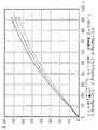
最後の図4に記載のグラフは、PMMA(ポリメタクリル酸メチル)製照明器具チューブのさまざまな壁厚の場合、角度γに対する角度δの依存性を示す。
この場合、パラメーター1、2および3によってチューブ半径のさまざまな状態を示すが、この場合Rmは平均チューブ半径、Raは照明器具チューブの外径であって、いずれも図3に示すものである。
より正確にいえばRmは、中心光線の角度γ=45°のとき、チューブ中心軸からプリズム頂点までの最大間隔と最小間隔の平均値である。従って、Rmは次のように計算される:
Rm=Rmin45°+Rmax45°/2。
The last graph in FIG. 4 shows the dependence of angle δ on angle γ for various wall thicknesses of PMMA (polymethyl methacrylate) luminaire tubes.
In this case, various states of the tube radius are indicated by
More precisely, Rm is the average value of the maximum and minimum intervals from the tube center axis to the prism apex when the angle γ of the central ray is 45 °. Therefore, Rm is calculated as follows:
Rm = Rmin 45 ° +
Claims (13)
複数のみぞが軸に平行に設けられ、これらのみぞはチューブの光を射出する側かつ軸方向に直径を切断する平面より下に配置され、その際これらのみぞの作用フランクと妨害フランクの向きは、ランプから生じた光線が事前指定かつ限定された射出角において方向変換されるような向きとすることを特徴とする、上記の保護チューブ。 In a luminaire with a protective tube, which is made of a transparent material and has a cylindrical tube with a Fresnel structure groove on the surface for guiding light, and a lamp is coaxially arranged inside the tube.
A plurality of grooves are provided parallel to the axis, and these grooves are arranged on the side of the tube where the light is emitted and below the plane whose diameter is cut in the axial direction, with the direction of the working flank and the blocking flank of these grooves The above-mentioned protective tube, characterized in that it is oriented so that the light rays generated from the lamp are redirected at a pre-specified and limited exit angle.
(法則1)

n':材料の屈折率
Rm:平均チューブ内側半径
Ra:チューブ外側半径
γ:中心光線のグローバル角度 An ideal line light source is provided at the center of the tube, and an inclination angle δ of the acting flank normal (WN) with respect to the central ray (S1) is approximately determined by the following law. 4. A lighting fixture with a protective tube according to 4.
(Law 1)
n ′: Refractive index of material Rm: Average tube inner radius Ra: Tube outer radius γ: Global angle of central ray
(法則2)
n':材料の屈折率
γ:中心光線のグローバル角度 6. An idealized line light source is provided at the center of the tube, and the inclination angle δ of the working flank normal (WN) with respect to the central ray is approximately determined by the following law. Lighting equipment with protective tube.
(Law 2)
n ′: Refractive index of material γ: Global angle of central ray
(法則3)
σ:中心光線に対する妨害フランク法線の傾斜角度
δ:中心光線に対する作用フランク法線の傾斜角度
n:チューブ内部および外部における媒質の屈折率
(ただし空気:n=1)
n':チューブ材料の屈折率 The lighting apparatus with a protective tube according to claim 3 or 4, characterized in that the inclination angle σ of the disturbing flank normal to the central ray of the line light source idealized at the tube center is obtained by the following law.
(Law 3)
σ: Inclination angle of disturbing flank normal to center ray δ: Inclination angle of action flank normal to center ray n: Refractive index of medium inside and outside of tube (air: n = 1)
n ′: Refractive index of the tube material
(法則4)
σ:中心光線に対する妨害フランク法線の傾斜角度
δ:中心光線に対する作用フランク法線の傾斜角度
n:チューブ内部および外部における媒質の屈折率
(ただし空気:n=1)
n':チューブ材料の屈折率 6. With the protection tube according to claim 3 and 5, wherein there is an ideal line light source at the center of the tube, and the inclination angle σ of the disturbing flank normal with respect to the center ray is obtained by the following law. lighting equipment.
(Rule 4)
σ: Inclination angle of disturbing flank normal to center ray δ: Inclination angle of action flank normal to center ray n: Refractive index of medium inside and outside of tube (air: n = 1)
n ′: Refractive index of the tube material
Priority Applications (1)
| Application Number | Priority Date | Filing Date | Title |
|---|---|---|---|
| JP2003430851A JP2005190834A (en) | 2003-12-25 | 2003-12-25 | Luminaire with protective tube |
Applications Claiming Priority (1)
| Application Number | Priority Date | Filing Date | Title |
|---|---|---|---|
| JP2003430851A JP2005190834A (en) | 2003-12-25 | 2003-12-25 | Luminaire with protective tube |
Publications (1)
| Publication Number | Publication Date |
|---|---|
| JP2005190834A true JP2005190834A (en) | 2005-07-14 |
Family
ID=34789104
Family Applications (1)
| Application Number | Title | Priority Date | Filing Date |
|---|---|---|---|
| JP2003430851A Pending JP2005190834A (en) | 2003-12-25 | 2003-12-25 | Luminaire with protective tube |
Country Status (1)
| Country | Link |
|---|---|
| JP (1) | JP2005190834A (en) |
-
2003
- 2003-12-25 JP JP2003430851A patent/JP2005190834A/en active Pending
Similar Documents
| Publication | Publication Date | Title |
|---|---|---|
| US11460623B2 (en) | LED lighting lamp | |
| EP3008377B1 (en) | Tubular lighting device | |
| TWI510738B (en) | Compact optical system and lenses for producing uniform collimated light | |
| US6289150B1 (en) | Side lighting optical conduit | |
| RU2552610C2 (en) | Illumination device and lens suitable for said illumination device | |
| US20170321865A1 (en) | Luminaire for emitting directional and non-directional light | |
| US20160131331A1 (en) | Luminaire for emitting directional and nondirectional light | |
| RU2004137463A (en) | PROJECTOR WITH FRENEL LENS WITH INTERCONNECTED CHANGE OF DISTANCE BETWEEN LIGHTING ELEMENTS | |
| WO1992022768A1 (en) | High aspect ratio light emitter having high uniformity and directionality | |
| JP5677443B2 (en) | Luminaire with light guide and Cartesian lens or Cartesian reflector | |
| US20160356940A1 (en) | Optical system and method for managing brightness contrasts between high brightness light sources and surrounding surfaces | |
| JP5620285B2 (en) | Luminous flux control member, light emitting device including the luminous flux control member, and illumination device including the luminous device | |
| WO2011024641A1 (en) | Optical element and light emitting device | |
| US20130176727A1 (en) | Segmented spotlight having narrow beam size and high lumen output | |
| EP2287641B1 (en) | Fresnel lens sheet and luminaire using the same | |
| RU2004137559A (en) | PROJECTOR WITH FRENEL LENS | |
| US11553566B2 (en) | Luminaire for emitting directional and non-directional light | |
| JP5931079B2 (en) | Lighting device, lighting fixture, and lighting system | |
| JP2009538499A (en) | Lighting system with color indicator | |
| JP2005190834A (en) | Luminaire with protective tube | |
| WO2014027917A1 (en) | Light-emitting diode lamp | |
| AU745328B2 (en) | A linear lighting device having co-extruded internally prismatically scored screens | |
| US12181145B2 (en) | Optical device | |
| JP4884980B2 (en) | Lighting device | |
| US11867365B2 (en) | Luminaire for emitting directional and non-directional light |
Legal Events
| Date | Code | Title | Description |
|---|---|---|---|
| A621 | Written request for application examination |
Free format text: JAPANESE INTERMEDIATE CODE: A621 Effective date: 20050930 |
|
| A977 | Report on retrieval |
Free format text: JAPANESE INTERMEDIATE CODE: A971007 Effective date: 20070601 |
|
| A131 | Notification of reasons for refusal |
Free format text: JAPANESE INTERMEDIATE CODE: A131 Effective date: 20070619 |
|
| A02 | Decision of refusal |
Free format text: JAPANESE INTERMEDIATE CODE: A02 Effective date: 20080325 |