JP2005183152A - Multi-direction switch - Google Patents
Multi-direction switch Download PDFInfo
- Publication number
- JP2005183152A JP2005183152A JP2003421686A JP2003421686A JP2005183152A JP 2005183152 A JP2005183152 A JP 2005183152A JP 2003421686 A JP2003421686 A JP 2003421686A JP 2003421686 A JP2003421686 A JP 2003421686A JP 2005183152 A JP2005183152 A JP 2005183152A
- Authority
- JP
- Japan
- Prior art keywords
- spring
- contact
- plunger
- contact spring
- tact
- Prior art date
- Legal status (The legal status is an assumption and is not a legal conclusion. Google has not performed a legal analysis and makes no representation as to the accuracy of the status listed.)
- Pending
Links
Images


Abstract
Description
本発明は、携帯電話、ポータブルステレオ、ビデオカメラ、デジタルカメラ、車載オーディオ等の操作用に組み込まれる多方向スイッチに関する。 The present invention relates to a multidirectional switch incorporated for operation of a mobile phone, a portable stereo, a video camera, a digital camera, an in-vehicle audio, and the like.
多方向スイッチは複数のスイッチ接点を備えていて、操作部に加えられる力の着力点や方向によって、それらのスイッチ接点のうちのあるものが選択されて動作するように構成されており、操作の違いに応じて何通りかの異なる信号を出力する。操作方法には、例えば直立に設けてある操作レバーあるいはステムを前後左右に傾けることにより、4通りまたはそれ以上の入力を行うものがある。さらに操作レバーの傾斜でなく、軸方向の動きに対応するスイッチ接点を設けて、入力の種類に軸方向に押す動きを加えたものもある。 The multi-directional switch has a plurality of switch contacts, and is configured such that a certain one of the switch contacts is selected and operated according to the force application point and direction of the force applied to the operation unit. Depending on the difference, several different signals are output. As an operation method, for example, there are methods in which four or more inputs are performed by tilting an operation lever or stem provided upright to the front, back, left and right. In addition, there is a switch contact corresponding to the movement in the axial direction instead of the inclination of the operation lever, and the movement of pushing in the axial direction is added to the type of input.
従来の多方向スイッチには、ケースの内部の基板の中央部およびその周辺の4方向の計5箇所に、浅いドーム状のタクトばねを1個ずつ、計5個配置し、タクトばね群の上に、プランジャを置いてカバーで覆った構成のものがあった。タクトばねはそれぞれ基板の環状固定接点に外周が乗っており、ドームの頂点の下方の基板上には円形固定接点が設けてある。プランジャの動作によってタクトばねの頂点が押されて湾曲が反転すると、ドームの頂点が下部の円形固定接点に接触して、円形固定接点とこれを囲む環状固定接点が導通する。 In a conventional multi-directional switch, five shallow dome-shaped tact springs are arranged at a total of five locations in the central part of the substrate inside the case and in the four directions around it. There was a configuration in which a plunger was placed and covered with a cover. The tact springs each have an outer periphery on the annular fixed contact of the substrate, and a circular fixed contact is provided on the substrate below the top of the dome. When the apex of the tact spring is pushed by the operation of the plunger and the curve is reversed, the apex of the dome comes into contact with the lower circular fixed contact, and the circular fixed contact and the annular fixed contact surrounding it are conducted.
この多方向スイッチは、静止状態でプランジャの下端が中央のタクトばねの頂点にほぼ接するが、プランジャの外周部は周辺のタクトばねの頂点との間に若干の隙間がある構成である。使用者がプランジャを垂直に押し下げると中央のタクトばねが押されて変形し、中央のスイッチ接点が導通して軸方向の動作を検出するが、周辺では前記の隙間によってプランジャの動きが吸収されるため、周辺のタクトばねはプランジャの下降によっては動作しない。 In this multidirectional switch, the lower end of the plunger is substantially in contact with the apex of the central tact spring in a stationary state, but the outer peripheral portion of the plunger has a slight gap between the apex of the peripheral tact spring. When the user depresses the plunger vertically, the central tact spring is pushed and deformed, and the central switch contact conducts to detect axial movement, but the movement of the plunger is absorbed by the gap in the periphery. Therefore, the surrounding tact springs do not operate when the plunger is lowered.
一方、使用者がプランジャを横に押すと、プランジャが傾斜して外周が前記の隙間以上に下がり、周辺のタクトばねを変形させてそのタクトバネが乗っている環状固定接点とその中心の円形固定接点が導通する。この時、中央のタクトばねは変形しないか、あるいは僅かしか変形せず、中央のスイッチはオンしない。このようなスイッチ構造と制御ソフトの併用により、4方向あるいは8方向などにプランジャを傾ける操作が検出される。 On the other hand, when the user pushes the plunger laterally, the plunger is inclined and the outer periphery is lowered to the gap or more, and the surrounding tact spring is deformed and the tact spring is on and the circular fixed contact at the center Is conducted. At this time, the center tact spring is not deformed or slightly deformed, and the center switch is not turned on. By using such a switch structure and control software in combination, an operation of tilting the plunger in four directions or eight directions is detected.
しかしこのような多方向スイッチは、各接点毎にタクトばねを用いるため、部品点数が多くなり、パッケージ寸法も大きくなって小型化に適しない。そこで本発明者らは先に特願2003−129634により、構造簡単な多方向スイッチを提案した。図5にその多方向スイッチを示す。 However, since such a multi-directional switch uses a tact spring for each contact, the number of parts increases and the package size increases, which is not suitable for miniaturization. Therefore, the present inventors previously proposed a multi-directional switch having a simple structure according to Japanese Patent Application No. 2003-129634. FIG. 5 shows the multidirectional switch.
図5の(A)は上面図、(B)は(A)のB−B断面図である。ガラス入りエポキシなどの基板1を底部とし、ポリイミドなどのスペーサ3、合成樹脂のカバー2を重ねて接合したケースにタクトばね4、接点ばね5それにプランジャ6を収容してある。タクトばね4は浅いドーム状であって基板1の中央に配置してあり、接点ばね5はステンレス鋼など導電材料の弾性薄板製で、図6に単体の形状を示す。図6(A)に見るように放射状に8本の腕を持ち、断面B−Bは同図(B)のごとくで、中央部に球面状の下向きの凹部を形成してあり、腕の先端部が下向きに反った形状である。
5A is a top view, and FIG. 5B is a cross-sectional view taken along the line BB in FIG. A
図5にて、プランジャ6は円板状のフランジ6aの上面にステム6bがついていて、カバー2の上面中央の穴から上に突き出しており、フランジ6aの下面中央に球面の突起6cがある。
In FIG. 5, the
カバー2とスペーサ3の間には薄い樹脂シートなどの可撓性の隔膜7を挟んで接合してあり、隔膜7はタクトばね4と接点ばね5を覆っている。隔膜7はプランジャ6のフランジ6aと接点ばね5の上面の間に完全に挟まれていてもよいが、図5では隔膜7の中央部に穴を開けてあって、プランジャ6の下面の突起6cがこの穴から下に出て、接点ばね5の中央部の球面状の凹部にはまり、接点ばね5の中心出しをしている。基板1の外周の複数箇所に円弧状の凹部1aが設けてあり、凹部1aの表面は導電被覆してあって、基板1の上下面の電極パターンを接続している。
A flexible diaphragm 7 such as a thin resin sheet is sandwiched between the
スペーサ3は中央部を打ち抜いて大きな穴にした形状で、この穴に接点ばね5を収容しているが、穴の外周から等間隔に8個のストッパー3aが内側に突き出していて、図5(A)に見るように、接点ばね5の8本の腕の先端がストッパー3a同士の間に挟まれて回り止めされている。
The
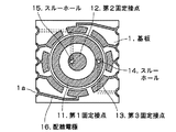
図7に示すのは基板1の上面に設けた電極のパターンで、中央の円形の第2固定接点12の周囲に環状の第1固定接点11があり、さらにその外側に扇形に分割した8個の第3固定接点13が設けてある。基板1の外周の複数の円弧状の凹部1aは導電被覆してあって、基板1の上下面の電極パターンを接続しており、扇形の第3固定接点13はそれぞれ配線電極16によって凹部1aの導電被覆に接続してある。環状の第1固定接点11と円形の第2固定接点12は、それぞれスルーホール14、15によって基板1の下面で凹部1aに接続している。
FIG. 7 shows a pattern of electrodes provided on the upper surface of the
図5と図7を見比べれば分かるように、ドーム状のタクトばね4は外周が環状の第1固定接点11に乗っているが、ドームの頂点は第2固定接点12から離れている。接点ばね5の8本の腕の先端は、それぞれ対応する扇形の第3固定接点3の上方にあって、第3固定接点3との間には隙間ができている。以上が先に出願した多方向スイッチの構造である。
As can be seen by comparing FIG. 5 and FIG. 7, the dome-
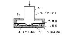
この多方向スイッチの動作を説明すると、まず、図8の矢印のようにプランジャ6のステム6bを下向きに押した時、フランジ6aの下面の突起6cが接点ばね5を介してタクトばね4の頂点を下に押し、荷重がある程度増したところでタクトばね4の湾曲が一気に反転して節度感を生じるとともに、タクトばね4の中央下面が図7の第2固定接点12に接する。これで、タクトばね4の外周が乗っている環状の第1固定接点11と第2固定接点12が導通する。この時、接点ばね5の各腕の先端は、図8に見るように基板1との間にまだ隙間があって、図7の扇形の第3固定接点13に接触せず、電気的導通は生じない。
The operation of this multi-directional switch will be described. First, when the
次に、プランジャ6のステム6bを、例えば図9の矢印のように右に押すと、プランジャ6が右下がりに傾き、フランジ6aの下面の突起6cが接点ばね5を介してタクトばね4を押して変形させ、節度感を生じる。同時に接点ばね5の右側の腕の先端が下がって、図7に示した基板1上の扇形の第3固定接点13に接触する。これにより第3固定接点13が接点ばね5とタクトばね4を介して第1固定接点11および第2固定接点12と導通する。接点ばね5の腕の先端は、第3固定接点13に接してからさらにプランジャ6が若干傾く余分の動きによって弾性変形し、接触圧を生じて電気的導通を確実にする。
Next, when the
このようにプランジャ6を傾斜させた時は、第1、第2、第3固定接点11、12、13の三つの固定接点が導通し、第1、第2固定接点11、12に関しては、図8のようにプランジャ6を下に押した時と同様の導通が生じるが、これについては機器の制御ソフトで第3固定接点13の状態も監視することにより、この動作がプランジャ6を下に押したのでなく、横に傾けたのであることを識別する。このような構造と作用によって、垂直に押し込む動作のほか、横向きに4方向あるいは8方向などに押す動作を検出する。
When the
しかしながら、このような従来の多方向スイッチには次の問題があった。すなわち図9のようにプランジャ6のステム6bを右に傾ければ接点ばね5の右側の腕の先端が下がって基板1上の固定接点(図7の第3固定接点13)に当たるが、この時、平面的に見て右側の腕の両隣りにある腕も、先端が下がってそれぞれの下にある固定接点に接触しがちなことである。図10にタクトばね4の右側部分を切り取ってその様子を示す。同図にてプランジャ6が右に傾くと、接点ばね5の右側の腕5a1の先端が下がって基板1上の固定接点に接触するが、このとき腕5a1の隣りの腕5a2の先端も下がって、対応する固定接点に接触してしまう。腕5a1によるスイッチ・オンだけを意図した操作の場合、これは誤動作である。
However, such a conventional multidirectional switch has the following problems. That is, if the
これを防ぐには、図5の構成において、同図(B)の接点ばね5の腕の先端と基板1の隙間を増して、腕の先端が基板1の固定接点に接触する時の傾斜角を大きくし、隣接する腕の先端と固定接点との距離に余裕を生じさせるのが一法であるが、それでは多方向スイッチ全体の寸法が大きくなって製品の小型化に逆行し、また、プランジャの傾斜角を増すことから操作性にも問題を生じる。本発明はこのような不利を避けながら前記の問題を解消するのを目的とする。
In order to prevent this, in the configuration of FIG. 5, the gap between the tip of the arm of the
上記の課題を解決するため、本発明では接点ばねの外周にリムを設け、ハブから延びる複数の腕の先端をこのリムで連結した形状にする。このような接点バネがどれかの腕の方向にプランジャと一体になって傾斜して、腕の先端のリム部分が基板上の固定接点に接触した場合、その両側の腕の先端部は従来の構造と違ってリムで拘束されているので、傾斜方向の腕の先端ほどには下がらず、基板上の固定接点との間に若干の隙間が確保される。これにより従来例におけるような誤動作、誤検出が大幅に低減する。 In order to solve the above problems, in the present invention, a rim is provided on the outer periphery of the contact spring, and the tips of a plurality of arms extending from the hub are connected to each other by the rim. When such a contact spring is tilted integrally with the plunger in the direction of one of the arms, and the rim portion at the tip of the arm comes into contact with the fixed contact on the board, Unlike the structure, it is constrained by a rim, so that it does not fall as much as the tip of the arm in the inclined direction, and a slight gap is secured between the fixed contact on the substrate. As a result, malfunctions and false detections as in the prior art are greatly reduced.
従来の多方向スイッチでは、プランジャを横に押す操作の際に、押す方向に隣接する接点がオンする誤動作が起こりがちで、これを防ぐには接点ばねの先端と基板上の固定接点の隙間を増すなどの処置が必要であり、このため製品の小型化が妨げられたりしていた。本発明では接点ばねの改良により、寸法の増加などを伴わずにこのような誤動作の発生を低減できる。接点ばねは各腕の先端をリムで連結した構造なので、従来のように枝分かれしたままで先端が自由な腕に比べて先端位置がばらつかず、製作が容易である。こうして小型で信頼性に富む横4方向、8方向等の多方向スイッチが廉価に実現される。 In the conventional multi-directional switch, when the plunger is pushed sideways, a malfunction that turns on the contact adjacent to the pushing direction tends to occur. To prevent this, the clearance between the tip of the contact spring and the fixed contact on the board is prevented. It is necessary to take measures such as increasing the size, and this has hindered downsizing of the product. In the present invention, the improvement of the contact spring can reduce the occurrence of such a malfunction without increasing the size. Since the contact spring has a structure in which the tip of each arm is connected by a rim, the tip position does not vary as compared to an arm that is branched and remains free as in the prior art, and is easy to manufacture. In this way, a small and reliable multi-directional switch such as four-way or eight-way is realized at low cost.
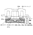
以下、図面に基づいて本発明の実施形態を説明する。図1は本発明の多方向スイッチの断面図で、図5の従来例とは部品形状が若干異なるものの、基本構成はほぼ同じである。すなわちガラス入りエポキシなどの基板21を底部とし、ポリイミドなどのスペーサ23、合成樹脂のカバー22を重ねて接合したケースにタクトばね24、接点ばね25、それにプランジャ26を収容してある。プランジャ26は円板状のフランジ26aと肩部26dとステム26bからなる形状で、カバー22の上面中央の穴から上に突き出しており、フランジ26aの下面中央になべ状の突起26cがある。この実施形態ではステム26bにキートップ28を取り付けてある。タクトばね24はここでも浅いドーム状である。
Hereinafter, embodiments of the present invention will be described with reference to the drawings. FIG. 1 is a cross-sectional view of a multidirectional switch according to the present invention. The basic configuration is substantially the same, although the part shape is slightly different from that of the conventional example of FIG. That is, a tact spring 24, a contact spring 25, and a plunger 26 are accommodated in a case in which a substrate 21 made of glass-containing epoxy or the like is used as a bottom and a spacer 23 made of polyimide or the like and a cover 22 made of synthetic resin are overlapped and joined. The plunger 26 has a disk-shaped
薄い樹脂シートなどの可撓性の隔膜27の外周をカバー22とスペーサ23の間に接合して挟持し、隔膜27はタクトばね24と接点ばね25を覆うとともに、中央部が接点ばね25とプランジャ26の間に挟まれているが、隔膜27の中心には丸穴が開けてあり、プランジャ26の下面の突起26cがこの穴から下に出て、接点ばね25の中央の下向きの凹部にはまり、接点ばね25の中心出しをしている。基板21の外周の複数箇所に円弧状の凹部21aが設けてあり、凹部21aの表面は導電被覆してあって、基板21の上下面の電極パターンを接続している。基板21の電極パターンは従来例の図7と同様のものである。
The outer periphery of a flexible diaphragm 27 such as a thin resin sheet is joined and sandwiched between the cover 22 and the spacer 23. The diaphragm 27 covers the tact spring 24 and the contact spring 25, and the central part is the contact spring 25 and the plunger. 26, a round hole is formed in the center of the diaphragm 27, and a protrusion 26c on the lower surface of the plunger 26 protrudes downward from this hole and fits into a downwardly recessed portion in the center of the contact spring 25. The contact spring 25 is centered. Arc-shaped
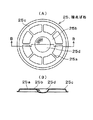
本発明に用いる接点ばね25を図2に示す。同図(A)は接点ばね25の平面図、(B)は(A)のB−B断面図である。中央のハブ25bにはプランジャ26の下面の突起26c(図1)がはまる凹部25dを形成してあり、ハブ25bから8本の腕25aが外向きに放射状に延びている。これらは図6の従来の接点ばね5と同様であるが、異なるのは外周に円環状のリム25cを設けたことで、腕25aの外端をリム25cにつないである。図2(B)に見るように、リム25cには絞り加工で段差を形成し、全体として皿を伏せたような形状にしてある。このような接点ばね25を用いるのが本発明の特徴である。
A contact spring 25 used in the present invention is shown in FIG. FIG. 4A is a plan view of the contact spring 25, and FIG. 4B is a sectional view taken along line BB in FIG. The
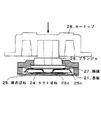
この実施形態の多方向スイッチの動作は基本的に従来例と同様である。まず、図3の矢印のようにキートップ28を下向きに押すと、プランジャ26の下面の突起26cが接点ばね25を介してタクトばね24の頂点を下に押して変形させ、頂点が基板21の固定接点に接触することにより中央のスイッチがオンする。この時、接点ばね25の外周のリム25cの下端は基板21との間にまだ隙間があって、基板上の固定接点に接触せず電気的導通は生じない。
The operation of the multidirectional switch of this embodiment is basically the same as that of the conventional example. First, when the key top 28 is pushed downward as shown by an arrow in FIG. 3, the protrusion 26 c on the lower surface of the plunger 26 is deformed by pushing down the apex of the tact spring 24 via the contact spring 25, and the apex is fixed to the substrate 21. The center switch is turned on by contacting the contact. At this time, there is still a gap between the lower end of the
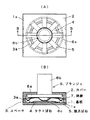
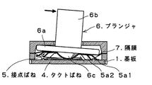
次に プランジャ26を横に押す場合を説明する。例えば図4(A)の矢印のようにキートップ28を右に押してプランジャ26を傾けると、下面の突起26cが接点ばね25を介してタクトばね24を押して変形させ、節度感を生じる。同時に接点ばね25のリム25cの右端が下がって基板21上の固定接点に接触することにより、その方向の外周スイッチ接点がオンする。リム25cは、固定接点に接してからさらにプランジャ16が若干傾く余分の動きによって弾性変形し、接触圧を生じて電気的導通を確実にする。
Next, the case where the plunger 26 is pushed sideways will be described. For example, when the key top 28 is pushed to the right as shown by the arrow in FIG. 4A and the plunger 26 is tilted, the projection 26 c on the lower surface pushes the tact spring 24 through the contact spring 25 to deform it, thereby generating a sense of moderation. At the same time, when the right end of the
プランジャ26を傾ける操作の時、従来の多方向スイッチでは、図10に見るように、接点ばね5が傾いた方向の腕5a1だけでなく、その隣りの腕5a2も先端が下がって基板1上の固定接点に接触し、誤動作となりやすかった。図4(A)では本発明の多方向スイッチについて、タクトばね24の右側部分を除去して描いてあるが、接点ばね25の右端近傍の丸で囲った部分を拡大して同図(B)に示す。図4(B)にて、リム25cの右端が図7に示す扇形の第3固定接点13の一つに接触して導通している。矢印を描いた箇所は、リム25cの右端が当たっている基板上の固定接点の隣の固定接点に、リム25cの下縁が面している部分である。
In the operation of tilting the plunger 26, in the conventional multi-directional switch, as shown in FIG. 10, not only the arm 5a1 in the direction in which the
図4(B)に示すように、矢印の箇所では、リム25cの下縁と基板21の上面の間に僅かながら隙間があって、接点ばね25と固定接点との導通が避けられる。これは図6の従来の多方向スイッチの接点ばね5では、各腕の先端が自由なため、ハブの傾斜に応じて各腕の先端が大きく下降するのに対し、図2の本発明の接点ばね25では、外周のリム25cが各腕25aの先端を連結して拘束しているため、接点ばね25を傾斜させた方向の腕に隣接する腕であっても、その先端の下降量は傾斜方向を向く腕の先端の下降量に達しないからである。
As shown in FIG. 4B, there is a slight gap between the lower edge of the
本発明の実施形態におけるその他の特徴について説明を補足する。まず、図1の実施形態は1枚のタクトばね24で構成しているが、タクトばね24を2枚重ねて配置する方法もある。スイッチを動作させる時の押し力や節度感はタクトばね24に依存するが、1枚のタクトばねでは特性のばらつきが大きくて微妙な動作特性を実現しにくいことがあり、2枚のタクトばね24を重ねて用いた方が所望の特性を得るのが容易な場合がある。 The description supplements other features in the embodiment of the present invention. First, although the embodiment of FIG. 1 is configured by one tact spring 24, there is a method in which two tact springs 24 are stacked. The pressing force and moderation feeling when the switch is operated depends on the tact spring 24, but there is a large variation in characteristics with one tact spring, and it may be difficult to realize subtle operating characteristics. In some cases, it is easier to obtain desired characteristics by using a plurality of layers.
また、隔膜27は周辺がカバー22とスペーサ23の間に挟まれて固着されてケースの内部を覆っており、前述のように隔膜27の中央には穴が開いていて、プランジャ26の下面の突起26cが穴から下に出ているが、接点ばね25のハブ25bとプランジャ26のフランジ26aに挟まれた穴周辺の隔膜27上下面を、接着剤あるいは接着シートによってハブ25bとフランジ26aに接合してある。すなわち接点ばね25と隔膜27とプランジャ26は一体化している。これにより接点ばね25は隔膜27で保持されて回転止めされ、向きが変わることがない。
Further, the periphery of the diaphragm 27 is sandwiched and fixed between the cover 22 and the spacer 23 to cover the inside of the case. As described above, a hole is formed in the center of the diaphragm 27 and the lower surface of the plunger 26 is formed. The protrusion 26c protrudes downward from the hole, but the upper and lower surfaces of the diaphragm 27 around the hole sandwiched between the
また、プランジャ26の肩部26dがカバー22の開口部にはまっていて、ステム26bが上に突き出しているが、肩部26dとこれがはまる開口部の平面形状、さらにはフランジ26aとこれを収めるカバー22の内壁形状を多角形、例えば8方向の傾斜を検出する多方向スイッチであれば8角形などにしてもよい。こうすればプランジャ26自体がカバー22の開口部によって形状的に回転止めされ、これと一体に接合された隔膜27や接点ばね25の回転止めが一層確実になる。
Further, the
また、図1では、基板21に設けた円環状の土手21bの中にタクトばね24を置いているが、隔膜27と同種の材料などで土手21bと外径が等しく中央に穴を開けたドーナツ状のカバーを作り、これを土手21bの上面に接合することにより、タクトばね24の外周を覆って土手21b内に保持する構造とすることもある。
In FIG. 1, the tact spring 24 is placed in an
1、21 基板
2、22 カバー
3、23 スペーサ
4、24 タクトばね
5、25 接点ばね
6、26 プランジャ
7、27 隔膜
11 第1固定接点
12 第2固定接点
13 第3固定接点
14、15 スルーホール
16 配線電極
28 キートップ
1, 21
Claims (6)
接点ばねは導電材料の弾性薄板製で、中央のハブと、ハブから放射状に延びる複数の腕と、各腕の先端を連結するリムからなり、リム下面が基板外周に環状に配置した接点群に隙間を隔てて面していることを特徴とする多方向スイッチ。 The case is configured with the base plate provided with a fixed contact as the bottom, a shallow dome-shaped tact spring is placed in the center of the base plate, and the contact spring and plunger are accommodated in the case in this order. A multi-directional switch protruding upward from the central hole,
The contact spring is made of an elastic thin plate of conductive material. It consists of a central hub, a plurality of arms extending radially from the hub, and a rim that connects the tips of the arms. A multidirectional switch characterized by facing a gap.
プランジャの傾斜時、前記タクトばねがプランジャに押されて湾曲が反転し、タクトばねの頂点が基板中央の固定接点に接触するとともに、接点ばねのリムの傾斜側が下がって基板外周の固定接点に接触することにより、基板中央の固定接点およびタクトばね外周の乗る環状の固定接点と基板外周の固定接点がタクトばねと接点ばねを介して導通することを特徴とする多方向スイッチ。 The multi-directional switch according to claim 1.
When the plunger is tilted, the tact spring is pushed by the plunger and the curve is reversed, and the apex of the tact spring contacts the fixed contact at the center of the board, and the inclined side of the rim of the contact spring falls and contacts the fixed contact on the outer periphery of the board By doing so, the fixed contact at the center of the substrate and the annular fixed contact on the outer periphery of the tact spring and the fixed contact on the outer periphery of the substrate are electrically connected via the tact spring and the contact spring.
プランジャの下面中央に突起を有し、接点ばねはハブに下向きの凹部を有するとともに外周が下に下がった形状であって、上記突起と凹部のはめ合いにより接点ばねを中心出しすることを特徴とする多方向スイッチ。 The multi-directional switch according to claim 1.
The plunger has a protrusion in the center of the lower surface, and the contact spring has a concave portion facing downward in the hub and the outer periphery is lowered downward, and the contact spring is centered by fitting the protrusion and the concave portion. Multi-directional switch to do.
外周をケースに固定した可撓性の隔膜をプランジャと接点ばねの間に設けて、タクトばねと接点ばねを覆ったことを特徴とする多方向スイッチ。 The multi-directional switch according to claim 1 or 3,
A multi-directional switch characterized in that a flexible diaphragm having an outer periphery fixed to a case is provided between a plunger and a contact spring to cover the tact spring and the contact spring.
外周をケースに固定し中央に穴を開けた可撓性の隔膜をプランジャと接点ばねの間に設けてタクトばねと接点ばねを覆い、前記プランジャ下面の突起が前記隔膜中央の穴から下に出て接点ばねのハブの凹部にはまることを特徴とする多方向スイッチ。 The multi-directional switch according to claim 3,
A flexible diaphragm with an outer periphery fixed to the case and a hole in the center is provided between the plunger and the contact spring to cover the tact spring and the contact spring, and the protrusion on the lower surface of the plunger protrudes downward from the hole in the middle of the diaphragm. A multidirectional switch that fits into the recess of the hub of the contact spring.
隔膜はプランジャと接点バネに挟まれた部分がプランジャおよび接点ばねの双方に接合してあって、これら3部品が一体化していることを特徴とする多方向スイッチ。
The multi-directional switch according to claim 4 or 5,
The multi-directional switch is characterized in that a portion of the diaphragm sandwiched between the plunger and the contact spring is joined to both the plunger and the contact spring, and these three parts are integrated.
Priority Applications (1)
| Application Number | Priority Date | Filing Date | Title |
|---|---|---|---|
| JP2003421686A JP2005183152A (en) | 2003-12-18 | 2003-12-18 | Multi-direction switch |
Applications Claiming Priority (1)
| Application Number | Priority Date | Filing Date | Title |
|---|---|---|---|
| JP2003421686A JP2005183152A (en) | 2003-12-18 | 2003-12-18 | Multi-direction switch |
Publications (1)
| Publication Number | Publication Date |
|---|---|
| JP2005183152A true JP2005183152A (en) | 2005-07-07 |
Family
ID=34782805
Family Applications (1)
| Application Number | Title | Priority Date | Filing Date |
|---|---|---|---|
| JP2003421686A Pending JP2005183152A (en) | 2003-12-18 | 2003-12-18 | Multi-direction switch |
Country Status (1)
| Country | Link |
|---|---|
| JP (1) | JP2005183152A (en) |
Cited By (2)
| Publication number | Priority date | Publication date | Assignee | Title |
|---|---|---|---|---|
| KR101369927B1 (en) | 2012-10-29 | 2014-03-25 | 태하메카트로닉스 (주) | Multi mode dial apparatus |
| KR20190103815A (en) * | 2018-02-28 | 2019-09-05 | 이씨에스프라임 주식회사 | Haptic control dial apparatus |
-
2003
- 2003-12-18 JP JP2003421686A patent/JP2005183152A/en active Pending
Cited By (3)
| Publication number | Priority date | Publication date | Assignee | Title |
|---|---|---|---|---|
| KR101369927B1 (en) | 2012-10-29 | 2014-03-25 | 태하메카트로닉스 (주) | Multi mode dial apparatus |
| KR20190103815A (en) * | 2018-02-28 | 2019-09-05 | 이씨에스프라임 주식회사 | Haptic control dial apparatus |
| KR102102847B1 (en) * | 2018-02-28 | 2020-04-22 | 이씨에스프라임 주식회사 | Haptic control dial apparatus |
Similar Documents
| Publication | Publication Date | Title |
|---|---|---|
| TWI405230B (en) | Multi-directional switch | |
| EP1069581B1 (en) | Multi-directional operating switch and multi-directional operating device using the same | |
| EP1814130B1 (en) | Slide switch | |
| JP3960132B2 (en) | Multidirectional operation switch and multidirectional input device using the same | |
| WO2009025529A2 (en) | Piezo-electric sensing unit and data input device using piezo-electric sensing | |
| US7652217B2 (en) | Rotary type pulse switch | |
| US20050224321A1 (en) | Multidirectional operation switch | |
| JP4330699B2 (en) | Multi-directional switch | |
| US8217282B2 (en) | Combination switch | |
| JP2005183152A (en) | Multi-direction switch | |
| JP3765723B2 (en) | Push-button switch | |
| JP2010021034A (en) | Push-switch | |
| JP2001350581A (en) | Input device | |
| JP3276302B2 (en) | Key switch and keyboard device using the same | |
| JP2005243320A (en) | Multidirectional switch | |
| JP2005032486A (en) | Multidirectional input device | |
| JP2878532B2 (en) | Control rod input device | |
| JP2004335264A (en) | Multidirectional switch | |
| JP4057500B2 (en) | Multi-directional input device | |
| JP5717430B2 (en) | Multi-directional input device | |
| JP4179909B2 (en) | pointing device | |
| JP2002313189A (en) | Multi directional switch | |
| JP2005019352A (en) | Multidirectional switch | |
| JP2002313188A (en) | Multi directional switch | |
| JP2006318860A (en) | Multidirectional input device |