JP2005181237A - Radar system - Google Patents
Radar system Download PDFInfo
- Publication number
- JP2005181237A JP2005181237A JP2003426104A JP2003426104A JP2005181237A JP 2005181237 A JP2005181237 A JP 2005181237A JP 2003426104 A JP2003426104 A JP 2003426104A JP 2003426104 A JP2003426104 A JP 2003426104A JP 2005181237 A JP2005181237 A JP 2005181237A
- Authority
- JP
- Japan
- Prior art keywords
- radar
- target
- angle
- monopulse
- distance
- Prior art date
- Legal status (The legal status is an assumption and is not a legal conclusion. Google has not performed a legal analysis and makes no representation as to the accuracy of the status listed.)
- Pending
Links
Images

Abstract
Description
本発明は、自車両と先行車もしくは障害物などの物標との距離,相対速度,角度を検出するミリ波レーダ装置に関する。 The present invention relates to a millimeter wave radar device that detects the distance, relative speed, and angle between a host vehicle and a preceding vehicle or an object such as an obstacle.
ミリ波等の電波を用いた電波レーダは、雨,霧等が存在する悪天候でも電波のビームの減衰量が小さく、遠距離まで到達するため、航空管制,気象観測分野で広く用いられてきた。最近では、自動車の予防安全の分野において、先行車との車間距離,相対速度,角度を計測するミリ波レーダが研究開発され、商品化されつつある。その電波レーダの方式にはいくつかあるが、代表的なものの一つとしてモノパルス方式のレーダがある。 Radio wave radars using millimeter waves and the like have been widely used in the field of air traffic control and weather observation because the attenuation of radio wave beams is small even in bad weather such as rain, fog, etc., and reach a long distance. Recently, in the field of preventive safety of automobiles, millimeter wave radars that measure the inter-vehicle distance, relative speed, and angle with the preceding vehicle are being researched and commercialized. There are several types of radio wave radar, but one of the typical ones is a monopulse radar.
モノパルス方式とは、ターゲット(検出対象物)で反射される電波を2つのアンテナで同時に受信し、2つの信号の位相差を検出することでターゲットの方位(角度)を検知する方式であり、機械的な可動部を有することなくターゲットの方位(角度)を検知することが出来るので、レーダの小型化,高信頼化に有効とされている(センサ・アクチュエータ/ウィーク‘99総合シンポジウム 自動車とセンサ技術、3.2方向検出方式、図4)。 The monopulse method is a method of detecting the azimuth (angle) of a target by simultaneously receiving radio waves reflected by the target (detection target) with two antennas and detecting the phase difference between the two signals. Can detect the azimuth (angle) of the target without having a moving part, so it is effective for miniaturization and high reliability of radar (Sensor / Actuator / Week '99 General Symposium Automotive and Sensor Technology 3.2 Direction detection method, Fig. 4).
モノパルス方式のレーダ装置では、2つの受信信号の和(以下、和信号と称する)及び2つの受信信号の差(以下、差信号と称する)を導出し、この和信号と差信号の電力の比率を、図8に示すような予め記憶した和信号/差信号の電力比率の特性と比較して先行車の角度を検知する。 In a monopulse radar device, a sum of two received signals (hereinafter referred to as a sum signal) and a difference between the two received signals (hereinafter referred to as a difference signal) are derived, and a ratio of the power of the sum signal and the difference signal. Is compared with the characteristic of the power ratio of the sum signal / difference signal stored in advance as shown in FIG. 8 to detect the angle of the preceding vehicle.
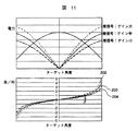
しかしながら、レーダ装置はアンテナやアンプを使用するため、温度特性や経時変化によりゲインが変化し、和信号,差信号の大きさが変化する。例えば、出荷時に記憶した角度テーブルが図11の203であったものが、温度変化によりアンプ118のゲインが変化すると、実際の角度テーブルが202もしくは204に変化する。 However, since the radar apparatus uses an antenna and an amplifier, the gain changes due to temperature characteristics and changes over time, and the magnitudes of the sum signal and difference signal change. For example, the angle table stored at the time of shipment is 203 in FIG. 11, but when the gain of the amplifier 118 changes due to a temperature change, the actual angle table changes to 202 or 204.
このため、実際の和信号と差信号の比率の特性と、記憶されている特性との間にずれが生じ、ターゲットの方位角度の検知制度が低下するという課題があった。 For this reason, there has been a problem that a deviation occurs between the actual characteristic of the ratio of the sum signal and the difference signal and the stored characteristic, and the detection system of the azimuth angle of the target is lowered.
本発明は、以上の事項を考慮してなされたものであり、ターゲット方位角度の検知精度低下を抑制することを目的とする。 The present invention has been made in consideration of the above matters, and an object thereof is to suppress a decrease in detection accuracy of a target azimuth angle.
モノパルスレーダに、少なくとも距離検知可能なレファレンスレーダを、モノパルスレーダの電波放射方向とレファレンスレーダの信号放射方向が所定の設定角を為すように組み合わせる。 A reference radar capable of detecting at least a distance is combined with the monopulse radar so that the radio wave radiation direction of the monopulse radar and the signal radiation direction of the reference radar make a predetermined set angle.
本発明によれば、モノパルスレーダの方位角度の検知精度低下を抑制することが出来る。 According to the present invention, it is possible to suppress a decrease in detection accuracy of the azimuth angle of the monopulse radar.
以下、添付図面を参照して本発明の実施形態について説明する。 Hereinafter, embodiments of the present invention will be described with reference to the accompanying drawings.
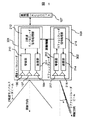
図1は本発明の一実施例を示すブロック図である。まず、本実施例のレーダ装置は大きくモノパルスレーダ部301とリファレンスレーダ部302から構成される。ここでは、モノパルスレーダ部301が2周波CW方式のレーダである場合について説明する。
FIG. 1 is a block diagram showing an embodiment of the present invention. First, the radar apparatus of the present embodiment is mainly composed of a
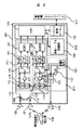
まず、2周波モノパルスレーダ部301の詳細について説明する。図2は2周波モノパルスレーダ部301のブロック図である。ミリ波発振器101は変調信号102を発生する変調器103により変調され、時分割でf1,f2(Δf:f2−f1)の二つの周波数の送信信号を送信アンテナ104から発射する。送信信号は先行車105で反射して受信信号となり、二つの受信アンテナ106,107で受信される。
First, details of the two-frequency
この時、先行車105と2周波モノパルスレーダ部301間に相対速度Vがある場合、ドップラ周波数fd1,fd2が発生し、受信信号の周波数はf1+fd1,f2+fd2となる。これらの受信信号は加算器109で加算され和(SUM)信号110に、また、減算器
111で減算され差(DIF)信号112に変換される。和信号110及び差信号112がミキサ113,114を通過すると、fd1,fd2のそれぞれの情報を含む、時分割した信号(中間周波数信号115,116(以下IF信号とする))となる。
At this time, when there is a relative speed V between the preceding
和信号と差信号のIF信号115,116はアンプ117,118により増幅された後、変調信号102に同期したスイッチ119,120により和信号,差信号毎に、それぞれ二つのLPF(ローパスフィルタ)121,122の方向に分配される。
After the IF signals 115 and 116 of the sum signal and the difference signal are amplified by the
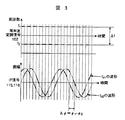
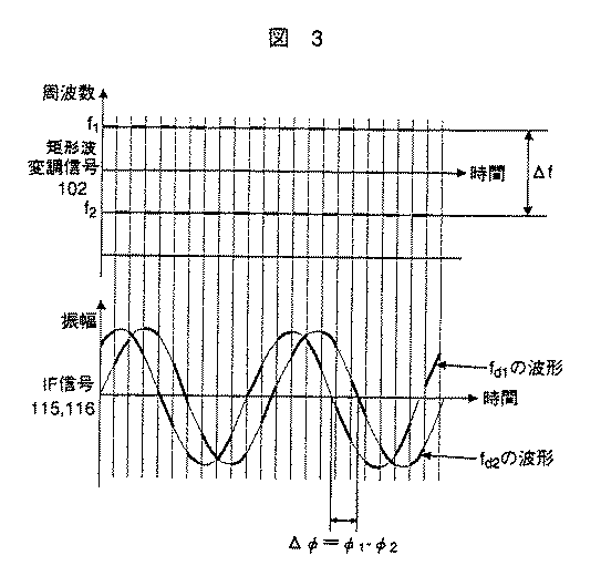
図3に変調信号102とIF信号115,116の関係を示す。LPF121,122を通過したIF信号は、通過する前の時分割したIF信号115,116の包絡線からなる二つの信号となる。この信号が変調周波数f1,f2に対するドップラ信号である。このドップラ信号をADC(A/D変換器)123,124によって離散値化し、DSP
(Digital Signal Processor)125でFFT(Fast Fourier Transform)解析処理すると、ドップラ周波数fd1,fd2と二つのアンテナによる受信信号の位相差φ1−φ2が求まる。
FIG. 3 shows the relationship between the
When FFT (Fast Fourier Transform) analysis processing is performed by the (Digital Signal Processor) 125, the Doppler frequencies f d1 and f d2 and the phase difference φ 1 -φ 2 of the received signals by the two antennas are obtained.
ここで、先行車105との相対速度Vは次式より求めることが出来る。
Here, the relative speed V with respect to the preceding
または Or
いま、fd1≪f1,fd2≪f2,Δf≪f1の場合、fd1≒fd2となるため、
Now, f d1 «f 1, f d2 «
また、車間距離Rは次式により表すことが出来る。 The inter-vehicle distance R can be expressed by the following equation.
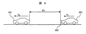
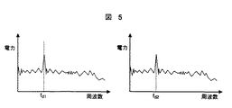
ここで、図4に示すように、自車両201とその前方に先行車105があり、それぞれの走行速度がV1,V2(V1≒V2)である時、相対速度は(V1−V2)となる。この時、相対速度に対するドップラ信号周波数をfd1,fd2とした場合に、その信号をFFT解析した結果を図5に示す。
Here, as shown in FIG. 4, there is a preceding
ここで、fd1≒fd2とすると、図5に示すようにドップラ周波数fd1に対応した周波数軸にスペクトルが現れる。この周波数情報と位相情報から、先行車両の相対速度(V1 −V2 )、及び距離Dを求めることが出来る。そして、求めた相対速度や距離はシステム制御マイコン126により、車両側上位システム127に出力される。
Here, when f d1 ≈f d2 , a spectrum appears on the frequency axis corresponding to the Doppler frequency f d1 as shown in FIG. From this frequency information and phase information, the relative speed (V 1 -V 2 ) and distance D of the preceding vehicle can be obtained. Then, the obtained relative speed and distance are output to the vehicle-
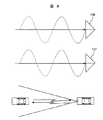
次に、角度検知方式について説明する。図6は二つの受信アンテナ106,107に正面方向から受信信号が入力する場合を示している。ターゲットがレーダの正面にある図6の場合、各受信アンテナに入力される信号は同位相であるため、加算することにより和信号は振幅が元の2倍になり、減算することにより差信号は振幅が0となることがわかる。
Next, the angle detection method will be described. FIG. 6 shows a case where a reception signal is input to the two
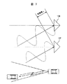
これに対し、図7は二つの受信アンテナにある角度から受信信号が入力する場合を示している。ターゲットがレーダに対してある角度を持つ図7の場合、各受信アンテナの信号は逆位相であるため、加算することにより和信号は振幅が0になり、減算することにより差信号は振幅が元の2倍になることがわかる。このように、二つの受信アンテナ106,107で受信する信号はターゲットから反射してくる信号の入力角度により位相差γが生じ、和信号と差信号の電力は、受信信号の入力する角度に対して図8に示すような特性を示す。この特性から、DSP125における和信号及び差信号のFFT解析結果からターゲットの方位角度を検知することができる。
On the other hand, FIG. 7 shows a case where the received signal is input from two angles at the two receiving antennas. In the case of FIG. 7 where the target has a certain angle with respect to the radar, the signals of the respective receiving antennas are in antiphase, so that the sum signal has an amplitude of 0 by addition and the difference signal has the original amplitude by subtraction. It turns out that it becomes twice. Thus, the signals received by the two receiving
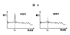
例えば、正面にあるターゲットからの受信信号により得られた和信号,差信号のFFT解析結果を図9に示す。図9では和信号は電力が大きく、差信号は電力が小さくなっている。これらの電力の比率が0であるとき、図8の差/和グラフから、そのターゲットの方位角度は0度と判断される。 For example, FIG. 9 shows the FFT analysis result of the sum signal and the difference signal obtained from the reception signal from the target in front. In FIG. 9, the sum signal has a large power and the difference signal has a small power. When the ratio of these electric powers is 0, the azimuth angle of the target is determined to be 0 degree from the difference / sum graph of FIG.
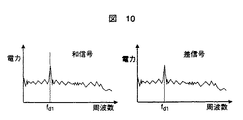
また、正面ではない、ある角度のターゲットからの受信信号により得られた和信号,差信号のFFT解析結果を図10に示す。図10では和信号と差信号は電力がほぼ等しくなっている。例えばこれらの電力の比率が1であるとき、図8の差/和グラフから、そのターゲットの方位角度はβ度と判断される。このように、モノパルス方式のレーダでは和信号と差信号の比率から角度を求めることができる。 Further, FIG. 10 shows the FFT analysis result of the sum signal and the difference signal obtained by the received signal from the target at a certain angle that is not the front. In FIG. 10, the sum signal and the difference signal have substantially the same power. For example, when the ratio of these powers is 1, the azimuth angle of the target is determined to be β degrees from the difference / sum graph of FIG. As described above, in the monopulse radar, the angle can be obtained from the ratio of the sum signal and the difference signal.
和信号と差信号の電力はターゲットの角度に対して、図8に示した特性をもつが、この特性はアンテナ,受信回路等のゲインによって異なる。 The power of the sum signal and the difference signal has the characteristic shown in FIG. 8 with respect to the target angle, but this characteristic varies depending on the gain of the antenna, the receiving circuit, and the like.
例えば203の特性を示すレーダを基準とすると、このレーダよりも差信号のゲインが大きいレーダの場合、その特性は図11の点線202のようになる。これに対し、このレーダよりも差信号のゲインが小さい場合、その特性は図11の破線204のようになる。
For example, when a radar having a characteristic of 203 is used as a reference, in the case of a radar having a gain of a difference signal larger than that of the radar, the characteristic is as indicated by a
このように和信号及び差信号の比率の特性は、アンテナ,受信回路等のゲインによって変化するので、個体差や製造ばらつきが生じる。これらの個体差,製造ばらつきを吸収するため、この特性は各個体毎に図2に示す角度テーブル記憶部128に記憶される。
As described above, the characteristics of the ratio of the sum signal and the difference signal vary depending on the gain of the antenna, the receiving circuit, etc., and therefore individual differences and manufacturing variations occur. In order to absorb these individual differences and manufacturing variations, this characteristic is stored in the angle
この2周波モノパルス方式の信号処理は、FFT解析の結果からスペクトルを検出し、1つの先行車両に対して、対応したスペクトルが存在し、その周波数から相対速度、また、位相情報から距離,電力強度から方位角度を同時に求めることが可能であるため、複雑な信号処理を用いることなく、安定した先行車両検知が可能となる利点がある。 In this signal processing of the two-frequency monopulse system, a spectrum is detected from the result of the FFT analysis, and a corresponding spectrum exists for one preceding vehicle, the relative speed is calculated from the frequency, the distance from the phase information, the power intensity. Since the azimuth angle can be obtained simultaneously from the above, there is an advantage that stable preceding vehicle detection can be performed without using complicated signal processing.
図1に戻って、リファレンスレーダ部302は送信部214,送信アンテナ216,受信アンテナ217,受信部213,リファレンスレーダ信号処理部215から構成される。リファレンスレーダ部302は、電波を送受信するものでも、レーザ光を送受信するものでもどちらでも良い。ただし、電波を用いた場合は電波信号に対する気象条件等の影響が2周波モノパルスレーダ部301と同じになるので、後述する角度検出値の補正の際に、それぞれのレーダ部301および302の検出結果が同一距離であるか否かの判定が容易である(図13,S506)。一方レーザを用いた場合は電波に比べて直進性が良いので、レファレンスレーダ部302のビーム幅を狭くすることが容易である。
Returning to FIG. 1, the
リファレンスレーダ部302は、少なくともターゲットの距離を検知できるものとし、角度に関しては検知することができる必要はなく、簡便で安価なレーダを使用することができる。
The
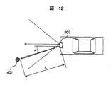
リファレンスレーダ部302は、その電波若しくはレーザの放射方向が2周波モノパルスレーダ部301の電波放射方向と所定の設定角αを為すように取り付けられており、リファレンスレーダ部302の送信する電波もしくはレーザ光は、送信アンテナ216により細く(例えば0.5度 に)絞られている。リファレンスレーダ部302の検知範囲の幅(ビーム幅)はより狭い方が、2周波モノパルスレーダ部の角度検知結果の補正制度が高くなる。ここでリファレンスレーダ部302の電波若しくはレーザの放射方向は、アンテナの向きを変えることで実現できる。
The
上記によりリファレンスレーダ部302は送信アンテナ216が向けられた規定の角度α方向にのみ電波等(電波,レーザなど)を放射するので、図12に示すように、2周波モノパルスレーダ部301の電波放射方向に対して角度αを為す方向に存在するターゲット401の距離Lを検知することが出来る。
As described above, the
リファレンスレーダ部302のリファレンスレーダ信号処理部215で算出したターゲット401の距離Lは2周波モノパルスレーダ信号処理部212に転送される。
The distance L of the
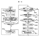
2周波モノパルスレーダ信号処理部212は、リファレンスレーダ信号処理部215からの距離情報に基づき、図13に示すフローに従って、本実施例の特徴である角度テーブル記憶部128の角度テーブルの補正処理を行う。図13に示す補正処理のフローについて以下に説明する。
Based on the distance information from the reference radar
まず、ステップS501において、ADCで離散値化した和信号と差信号のFFT処理を行う。次にステップS502において、FFT処理結果からターゲットのスペクトルを抽出する。続いてステップS503において距離,相対速度、及び角度を計算し、ステップS504でリファレンスレーダ部302からの距離検知情報があるかを判定する。
First, in step S501, FFT processing is performed on the sum signal and the difference signal that have been converted to discrete values by the ADC. Next, in step S502, a target spectrum is extracted from the FFT processing result. Subsequently, in step S503, the distance, relative speed, and angle are calculated, and in step S504, it is determined whether there is distance detection information from the
ステップS504で距離検知情報がない場合はそのままステップS505に進み、検知したターゲットの情報を上位システムに出力する。ステップS504でリファレンスレーダ部302からの距離検知情報がある場合はステップS506に進む。
If there is no distance detection information in step S504, the process proceeds to step S505 as it is, and the detected target information is output to the host system. If there is distance detection information from the
ステップS506では、2周波モノパルスレーダ部の信号処理結果にリファレンスレーダ部302の検知距離と同じ距離を示すターゲットが存在するか判定する。
In step S506, it is determined whether or not a target having the same distance as the detection distance of the
ここで、そのようなターゲットが存在しない場合はステップS505に進み、検知したターゲットの情報を上位システムに出力する。ここで上記のようなターゲットが存在する場合はステップS507に進む。 If there is no such target, the process proceeds to step S505, and the detected target information is output to the host system. If there is such a target, the process proceeds to step S507.
ステップ507においては、リファレンスレーダ部302と同距離のターゲット数が1個であるか判定する。ここでターゲットが2個以上である場合は、どのターゲットがリファレンスレーダ部302の検出物と同じターゲットであるか判断できないため、補正処理は行わずにステップS505に進む。ここでターゲット1個である場合は、そのターゲットはリファレンスレーダ部302で検出しているターゲットと同じであると判断し、ステップ508に進む。
In
ステップS508では、ステップ507で2周波モノパルスレーダ部301とリファレンスレーダ部302の双方で検出されていると判断されたターゲットに対し、2周波モノパルスレーダ部301において検出された角度と、リファレンスレーダ部302の設定角α(図12参照)との差(以下、角度差と称する)が、ある規定値(例えば0.5 度)より大きいか判定する。
In step S508, the angle detected by the two-frequency
ここで上記の角度差が規定値より小さい場合は、2周波モノパルスレーダ部301の角度検出結果は正しいものと判断し、補正処理を行うことなくステップS505に進む。ここで上記の角度差が規定値以上である場合は、角度検出値が真値に対してずれているものと判断し、ステップS509において角度テーブル記憶部128に記録された和信号及び差信号の比率特性を補正し、ステップS510で実際に角度テーブル記憶部のデータを更新し、ステップS511で、2周波モノパルスレーダ部301の角度検出結果に対し、再計算を行う。
If the angle difference is smaller than the specified value, it is determined that the angle detection result of the two-frequency
なお、次の計算ステップから補正,更新後の和信号及び差信号の比率特性を用いることしても良いが、本実施例のように、特性変化を検出したときの検知結果から補正値を用いるようにした方が、検出結果の信頼性が高くなる。 Although the ratio characteristics of the sum signal and difference signal after correction and update may be used from the next calculation step, the correction value is used from the detection result when the characteristic change is detected as in this embodiment. The detection result is more reliable.
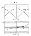
続いて、角度テーブルの補正方法について、図14を使用して説明する。図14の実線601は角度テーブル記憶部128に記憶されている角度テーブルである。今、2周波モノパルスレーダ信号処理部212で計算された差/和がBである時、その値から算出される方位角度値はβとなる。このβの真値がαである時、角度テーブルは実線601から破線602に補正される。そして、この補正した角度テーブル602をステップS510で角度テーブル記憶部128に記憶する。ステップS511では補正した角度テーブルに基づき、2周波モノパルス信号処理部は、ステップS503で算出したターゲットすべてに関して方位角度を再計算する。そして、ステップS505において、再計算した方位角度と距離,相対速度情報を上位システムに出力する。
Next, the angle table correction method will be described with reference to FIG. A
以上のように本実施例によれば、従来の信号処理の構成に簡易な変更を追加することでターゲットの角度検知の基準となる信号を検出することができるので、モノパルス方式の角度計測結果の誤差を求め補正することができる。よってモノパルス方式のレーダ装置の角度検知精度を向上することができる。 As described above, according to this embodiment, it is possible to detect a signal serving as a reference for target angle detection by adding a simple change to the conventional signal processing configuration. An error can be obtained and corrected. Therefore, the angle detection accuracy of the monopulse radar device can be improved.
最後に、本発明の好適な実施形態を列挙する。 Finally, preferred embodiments of the present invention are listed.
車両前方に設置され、前方車両もしくは障害物などの物標との距離,相対速度,角度を計測するミリ波レーダ装置において、角度検知方法の異なる2種類のレーダをそなえ、その一方のレーダの角度計測結果を基準として、他方の角度計測結果を補正することを特徴とするミリ波レーダ装置。 A millimeter-wave radar device that is installed in front of a vehicle and measures the distance, relative speed, and angle with a target vehicle such as a preceding vehicle or an obstacle, has two types of radars with different angle detection methods, and the angle of one of the radars A millimeter-wave radar device that corrects the other angle measurement result based on the measurement result.
車両前方に設置され、前方車両もしくは障害物などの物標との距離,相対速度,角度を計測するミリ波レーダ装置において、角度検知方法がモノパルス方式のレーダと、角度検知方式がモノパルス方式でないレーダをそなえ、角度検知方式がモノパルス方式でないレーダの角度計測結果を基準として、モノパルス方式の角度計測結果を補正することを特徴とするミリ波レーダ装置を提供する。 In a millimeter-wave radar device that is installed in front of a vehicle and measures the distance, relative speed, and angle with a target vehicle such as a preceding vehicle or an obstacle, the radar that uses the monopulse method for the angle detection method and the radar that does not use the monopulse method for the angle detection method Accordingly, a millimeter wave radar device is provided that corrects the angle measurement result of the monopulse method with reference to the angle measurement result of the radar whose angle detection method is not the monopulse method.
車両前方に設置され、前方車両もしくは障害物などの物標との距離,相対速度,角度を計測するミリ波レーダ装置において、角度検知方法がモノパルス方式のレーダと、設定した既知の角度方向に狭角のビームを送受信することで、該設定角度に存在する物標の距離を検知するレーダをそなえ、狭角ビームを送受信するレーダの該設定を基準として、モノパルス方式の角度計測結果を補正することを特徴とするミリ波レーダ装置。 In a millimeter wave radar device that is installed in front of a vehicle and measures the distance, relative speed, and angle with a target vehicle such as a preceding vehicle or an obstacle, the angle detection method is narrower than a monopulse radar and a set known angle direction. Provide a radar that detects the distance of a target that exists at the set angle by transmitting and receiving an angular beam, and correct the angle measurement result of the monopulse system based on the setting of the radar that transmits and receives a narrow angle beam Millimeter wave radar device.
上記のようなミリ波レーダ装置は、角度補正結果を記憶する記憶手段を備えることが望ましい。 The millimeter wave radar device as described above preferably includes storage means for storing the angle correction result.
101…ミリ波発振器、102…変調信号、103…変調器、104…送信アンテナ、105…先行車、106,107…受信アンテナ、110…和(SUM)信号、111…減算器、112…差(DIF)信号、113,114…ミキサ、115,116…中間周波数信号、117,118…アンプ、119,120…スイッチ、121,122…LPF(ローパスフィルタ)、123,124…A/D変換器、125…DSP(Digital
Signal Processor) 、126…システム制御マイコン、127…車両側上位システム、
210…2周波モノパルスレーダ受信部、211…2周波モノパルスレーダ送信部、212…2周波モノパルスレーダ信号処理部、213…リファレンスレーダ受信部、214…リファレンスレーダ送信部、215…リファレンスレーダ信号処理部、216…リファレンスレーダ送信アンテナ、217…リファレンスレーダ受信アンテナ、301…2周波モノパルスレーダ部、302…リファレンスレーダ部、401…ターゲット。
DESCRIPTION OF
Signal processor), 126 ... system control microcomputer, 127 ... vehicle side host system,
210: 2-frequency monopulse radar receiver 211: 2-frequency monopulse radar transmitter 212: 2-frequency monopulse radar signal processor 213: Reference radar receiver 214: Reference radar transmitter 215: Reference radar signal processor 216: Reference radar transmitting antenna, 217: Reference radar receiving antenna, 301: Dual frequency monopulse radar unit, 302: Reference radar unit, 401: Target.
Claims (9)
少なくともターゲットとの距離を検出するリファレンスレーダ部とを備え、
前記リファレンスレーダ部の信号放射方向が、前記モノパルスレーダ部の電波放射方向と所定の角度を為すことを特徴とするレーダ装置。 A monopulse radar unit that includes a transmitting unit that radiates radio waves in front and two or more receiving antennas that receive reflected waves from the target, and that detects at least a distance and an angle with the target;
A reference radar unit that detects at least the distance to the target,
A radar apparatus, wherein a signal radiation direction of the reference radar unit makes a predetermined angle with a radio wave radiation direction of the monopulse radar unit.
少なくともターゲットとの距離を検出するリファレンスレーダ部とを備え、
少なくともターゲットとの距離を検出するリファレンスレーダを、その電波放射方向が前記モノパルスレーダの電波放射方向と所定の設定角を為すように配置し、
前記モノパルスレーダが検知したターゲットの角度と前記設定角との差が所定以上である場合は、前記モノパルスレーダの角度検出結果を補正することを特徴とするレーダ装置。 A monopulse radar unit that includes a transmitting unit that radiates radio waves in front and two or more receiving antennas that receive reflected waves from the target, and that detects at least a distance and an angle with the target;
A reference radar unit that detects at least the distance to the target,
A reference radar that detects at least the distance to the target is disposed so that the radio wave radiation direction forms a predetermined set angle with the radio wave radiation direction of the monopulse radar,
A radar apparatus, wherein when the difference between the target angle detected by the monopulse radar and the set angle is greater than or equal to a predetermined value, the angle detection result of the monopulse radar is corrected.
少なくともターゲットとの距離を検出するリファレンスレーダを、その電波放射方向が前記モノパルスレーダの電波放射方向と所定の設定角を為すように配置し、
前記モノパルスレーダが検知したターゲットの角度と前記設定角との差が所定以上である場合は、前記モノパルスレーダの角度検出結果を補正することを特徴とするモノパルスレーダの角度検出結果補正方法。 A correction method of an angle detection result of a monopulse radar that includes a transmitter that radiates a radio wave forward and two or more receiving antennas that receive a reflected wave from a target, and detects at least a distance and an angle with the target,
A reference radar that detects at least the distance to the target is disposed so that the radio wave radiation direction forms a predetermined set angle with the radio wave radiation direction of the monopulse radar,
An angle detection result correction method for a monopulse radar, wherein the angle detection result of the monopulse radar is corrected when the difference between the target angle detected by the monopulse radar and the set angle is greater than or equal to a predetermined value.
前記モノパルスレーダによって検出されたターゲットの中から、前記レファレンスレーダにより検出されたターゲットと略同一の距離を示すターゲットを選出し、該ターゲットが一つの場合に補正を行うことを特徴とするモノパルスレーダの角度検出結果補正方法。 In claim 8,
A target of a monopulse radar, wherein a target having a distance substantially the same as the target detected by the reference radar is selected from the targets detected by the monopulse radar, and correction is performed when there is only one target. Angle detection result correction method.
Priority Applications (1)
| Application Number | Priority Date | Filing Date | Title |
|---|---|---|---|
| JP2003426104A JP2005181237A (en) | 2003-12-24 | 2003-12-24 | Radar system |
Applications Claiming Priority (1)
| Application Number | Priority Date | Filing Date | Title |
|---|---|---|---|
| JP2003426104A JP2005181237A (en) | 2003-12-24 | 2003-12-24 | Radar system |
Publications (1)
| Publication Number | Publication Date |
|---|---|
| JP2005181237A true JP2005181237A (en) | 2005-07-07 |
Family
ID=34785731
Family Applications (1)
| Application Number | Title | Priority Date | Filing Date |
|---|---|---|---|
| JP2003426104A Pending JP2005181237A (en) | 2003-12-24 | 2003-12-24 | Radar system |
Country Status (1)
| Country | Link |
|---|---|
| JP (1) | JP2005181237A (en) |
Cited By (6)
| Publication number | Priority date | Publication date | Assignee | Title |
|---|---|---|---|---|
| JP2007033156A (en) * | 2005-07-25 | 2007-02-08 | Secom Co Ltd | Radar device |
| CN100412567C (en) * | 2006-05-11 | 2008-08-20 | 哈尔滨工业大学(威海) | Automobile collision-proof one-dimensional scanning lidar system |
| JP2012205213A (en) * | 2011-03-28 | 2012-10-22 | Mitsubishi Electric Corp | Tracking antenna device adjustment method and tracking antenna device |
| RU2600109C1 (en) * | 2015-04-16 | 2016-10-20 | Акционерное общество "Уральское проектно-конструкторское бюро "Деталь" | Monopulse radar of millimetre range |
| CN112834995A (en) * | 2020-12-30 | 2021-05-25 | 纵目科技(上海)股份有限公司 | Vehicle-mounted millimeter wave radar angle calibration method and system and electronic equipment |
| CN112924976A (en) * | 2019-12-08 | 2021-06-08 | 钱仁贵 | Target detection method and device based on ultrasonic radar |
-
2003
- 2003-12-24 JP JP2003426104A patent/JP2005181237A/en active Pending
Cited By (7)
| Publication number | Priority date | Publication date | Assignee | Title |
|---|---|---|---|---|
| JP2007033156A (en) * | 2005-07-25 | 2007-02-08 | Secom Co Ltd | Radar device |
| CN100412567C (en) * | 2006-05-11 | 2008-08-20 | 哈尔滨工业大学(威海) | Automobile collision-proof one-dimensional scanning lidar system |
| JP2012205213A (en) * | 2011-03-28 | 2012-10-22 | Mitsubishi Electric Corp | Tracking antenna device adjustment method and tracking antenna device |
| RU2600109C1 (en) * | 2015-04-16 | 2016-10-20 | Акционерное общество "Уральское проектно-конструкторское бюро "Деталь" | Monopulse radar of millimetre range |
| CN112924976A (en) * | 2019-12-08 | 2021-06-08 | 钱仁贵 | Target detection method and device based on ultrasonic radar |
| CN112834995A (en) * | 2020-12-30 | 2021-05-25 | 纵目科技(上海)股份有限公司 | Vehicle-mounted millimeter wave radar angle calibration method and system and electronic equipment |
| CN112834995B (en) * | 2020-12-30 | 2024-03-22 | 纵目科技(上海)股份有限公司 | Vehicle millimeter wave radar angle calibration method and system and electronic equipment |
Similar Documents
| Publication | Publication Date | Title |
|---|---|---|
| JP4007498B2 (en) | Automotive radar equipment | |
| US6204803B1 (en) | Radar apparatus | |
| JPH09502017A (en) | Monopulse azimuth radar system for self-propelled vehicle tracking | |
| JP4396436B2 (en) | Target detection device | |
| US10823846B2 (en) | Object detection method and object detection device | |
| WO2020034243A1 (en) | Method for dynamically adjusting fmcw radar distance resolution and distance measurement range | |
| JPWO2007043479A1 (en) | Radar equipment | |
| JP4281632B2 (en) | Target detection device | |
| JP2014215087A (en) | Radar device and inspection system | |
| US6040795A (en) | Vehicle-mounted radar apparatus | |
| WO2002099456A1 (en) | Radar device | |
| JP2003167047A (en) | Miss-pairing determination and signal processing method for rm-cw radar | |
| JP4591507B2 (en) | Radar equipment | |
| JP5059717B2 (en) | Monopulse radar device | |
| JP4314262B2 (en) | Automotive radar equipment | |
| US7230565B2 (en) | Radar | |
| JP2005181237A (en) | Radar system | |
| JP2010175471A (en) | Radar apparatus | |
| JP3720662B2 (en) | Automotive radar equipment | |
| US6492937B1 (en) | High precision range measurement technique | |
| JP3477133B2 (en) | Radar equipment | |
| JP3577237B2 (en) | Radar equipment for vehicles | |
| JP4910955B2 (en) | Radar equipment for vehicles | |
| JP3070589B2 (en) | Radar equipment | |
| JP2006058135A (en) | Moving body detector and detecting method |