JP2005181097A - Ultrasonic fluid measuring device - Google Patents
Ultrasonic fluid measuring device Download PDFInfo
- Publication number
- JP2005181097A JP2005181097A JP2003422003A JP2003422003A JP2005181097A JP 2005181097 A JP2005181097 A JP 2005181097A JP 2003422003 A JP2003422003 A JP 2003422003A JP 2003422003 A JP2003422003 A JP 2003422003A JP 2005181097 A JP2005181097 A JP 2005181097A
- Authority
- JP
- Japan
- Prior art keywords
- time
- ultrasonic
- fluid
- measurement
- reception
- Prior art date
- Legal status (The legal status is an assumption and is not a legal conclusion. Google has not performed a legal analysis and makes no representation as to the accuracy of the status listed.)
- Withdrawn
Links
Images

Classifications
-
- G—PHYSICS
- G01—MEASURING; TESTING
- G01N—INVESTIGATING OR ANALYSING MATERIALS BY DETERMINING THEIR CHEMICAL OR PHYSICAL PROPERTIES
- G01N2291/00—Indexing codes associated with group G01N29/00
- G01N2291/02—Indexing codes associated with the analysed material
- G01N2291/028—Material parameters
- G01N2291/02836—Flow rate, liquid level
-
- G—PHYSICS
- G01—MEASURING; TESTING
- G01N—INVESTIGATING OR ANALYSING MATERIALS BY DETERMINING THEIR CHEMICAL OR PHYSICAL PROPERTIES
- G01N2291/00—Indexing codes associated with group G01N29/00
- G01N2291/02—Indexing codes associated with the analysed material
- G01N2291/028—Material parameters
- G01N2291/02845—Humidity, wetness
-
- G—PHYSICS
- G01—MEASURING; TESTING
- G01N—INVESTIGATING OR ANALYSING MATERIALS BY DETERMINING THEIR CHEMICAL OR PHYSICAL PROPERTIES
- G01N2291/00—Indexing codes associated with group G01N29/00
- G01N2291/02—Indexing codes associated with the analysed material
- G01N2291/028—Material parameters
- G01N2291/02872—Pressure
-
- G—PHYSICS
- G01—MEASURING; TESTING
- G01N—INVESTIGATING OR ANALYSING MATERIALS BY DETERMINING THEIR CHEMICAL OR PHYSICAL PROPERTIES
- G01N2291/00—Indexing codes associated with group G01N29/00
- G01N2291/02—Indexing codes associated with the analysed material
- G01N2291/028—Material parameters
- G01N2291/02881—Temperature
Landscapes
- Measuring Volume Flow (AREA)
- Investigating Or Analyzing Materials By The Use Of Ultrasonic Waves (AREA)
Abstract
Description
本発明は、超音波流体計測装置に関し、詳細には、被験流体の音響的減衰が大きい場合に、伝搬時間測定の基準となるゼロクロス点を正確に特定するための技術に関する。 The present invention relates to an ultrasonic fluid measuring device, and more particularly to a technique for accurately specifying a zero-crossing point that is a reference for propagation time measurement when acoustic attenuation of a test fluid is large.
従来、一対のトランスデューサを流れの方向にずらして配置し、上流側のトランスデューサから流れに対して順方向に超音波を発射し、これが下流側のトランスデューサにより受信されるまでの第1の伝搬時間を測定するとともに、下流側のトランスデューサから流れに対して逆方向に超音波を発射し、これが上流側のトランスデューサにより受信されるまでの第2の伝搬時間を測定し、測定された各伝搬時間をもとに、被験流体の流量等を検出する流体計測装置が知られている。この超音波流体計測装置では、第1及び第2の伝搬時間を測定する際に、ゼロクロス点と呼ばれる、トランスデューサの出力電圧がゼロレベルを過ぎる時点を特定し、超音波が発射された時点からこのゼロクロス点までの時間を測定している。ゼロクロス点の特定は、トランスデューサの出力電圧に関するしきい値を予め設定しておき、実際に得られた出力電圧がこのしきい値に達した時点を特定することによるのが一般的である(特許文献1)。
しかしながら、上記の超音波流体計測装置には、被験流体が水素ガス等の音響的減衰の大きなものである場合に、次のような問題がある。
すなわち、水素ガス等を被験流体とする場合は、発射された超音波が受信側のトランスデューサに到達するまでに大きく減衰する。このため、トランスデューサ出力の超音波成分が小さくなる一方、これに重畳するノイズ成分が相対的に大きくなることである。このため、トランスデューサの出力電圧としきい値との比較による上記の方法では、本来のゼロクロス点よりも前に偶発的に大きなノイズを入力し、出力電圧がしきい値に達したときに、その時点で誤ったゼロクロス点(本来のゼロクロス点よりも早い。)が特定されることになる。他方、これを回避するため、ノイズ成分に対する余裕を持たせて大きなしきい値を設定した場合は、超音波の減衰の程度やノイズの大きさ次第で、本来のゼロクロス点を特定し損なうことが考えられる。ゼロクロス点の特定を誤った場合は、流量等の計測結果において、超音波の周波数に応じた大きな誤差を来すことになる。
However, the above ultrasonic fluid measuring device has the following problems when the test fluid has a large acoustic attenuation such as hydrogen gas.
That is, when hydrogen gas or the like is used as the test fluid, the emitted ultrasonic wave is greatly attenuated before reaching the receiving-side transducer. For this reason, while the ultrasonic component of a transducer output becomes small, the noise component superimposed on this becomes relatively large. For this reason, in the above method by comparing the output voltage of the transducer and the threshold value, when a large noise is accidentally input before the original zero cross point and the output voltage reaches the threshold value, In this case, an erroneous zero cross point (which is earlier than the original zero cross point) is specified. On the other hand, in order to avoid this, if a large threshold is set with a margin for the noise component, it may fail to specify the original zero cross point depending on the degree of attenuation of the ultrasonic wave and the size of the noise. Conceivable. If the zero-cross point is incorrectly specified, a large error corresponding to the frequency of the ultrasonic wave is caused in the measurement result such as the flow rate.
本発明は、水素ガス等の音響的減衰の大きなものを被験流体とする場合に、ノイズ成分による影響を受けず、ゼロクロス点を正確に特定することを可能とし、正確な計測結果を得ることを目的とする。 The present invention makes it possible to accurately identify the zero-crossing point without being affected by noise components and to obtain an accurate measurement result when a test fluid having a large acoustic attenuation such as hydrogen gas is used. Objective.
本発明は、超音波流体計測装置を提供する。本発明に係る装置は、被験流体を流通させる測定管と、測定管を横断させて設定した超音波伝搬線上に設置され、流れに対して順方向に超音波を発射する第1のトランスデューサと、超音波伝搬線上に、第1のトランスデューサよりも下流に設置され、流れに対して逆方向に超音波を発射する第2のトランスデューサとを含んで構成される。第1又は第2のトランスデューサから発射された超音波を受信したトランスデューサの出力が所定のレベルに達する時点を受信時点として特定し、特定した受信時点をもとに、第1又は第2のトランスデューサから発射された超音波の、受信側のトランスデューサまでの各伝搬時間を測定し、測定した各伝搬時間をもとに、被験流体に関する所定の演算を行う。ここで、第1又は第2のトランスデューサから超音波が発射された後、所定の時間が経過するまでを禁止期間とし、この禁止期間では、受信時点の特定を禁止する。 The present invention provides an ultrasonic fluid measuring device. An apparatus according to the present invention includes a measurement tube for circulating a test fluid, a first transducer that is installed on an ultrasonic propagation line set across the measurement tube, and emits ultrasonic waves in a forward direction with respect to the flow; A second transducer that is disposed downstream of the first transducer on the ultrasonic wave propagation line and emits ultrasonic waves in a direction opposite to the flow is configured. A time point at which the output of the transducer that has received the ultrasonic wave emitted from the first or second transducer reaches a predetermined level is specified as a reception time point, and from the first or second transducer based on the specified reception time point Each propagation time of the emitted ultrasonic wave to the transducer on the receiving side is measured, and a predetermined calculation regarding the test fluid is performed based on each measured propagation time. Here, after the ultrasonic wave is emitted from the first or second transducer, a period until a predetermined time elapses is set as a prohibited period, and in this prohibited period, specification of the reception time is prohibited.
本発明では、受信時点の特定に際し、超音波が発射されてから所定の時間が経過するまでの間(すなわち、禁止期間)、この特定を禁止することとしている。このため、超音波の減衰が大きく、トランスデューサ出力に相対的に大きなノイズ成分が重畳する場合であっても、本来の受信時点前に偶発的に入力したノイズにより受信時点が誤って特定されるのを防止することができる。また、このように受信時点の誤った特定が防止されることで、受信時点の特定に関する所定のレベルの適正化を図るとともに、この所定のレベルとの比較において、ある程度の大きさを持つ超音波成分を採用することが可能となるので、受信時点を正確、かつ確実に特定することができる。 In the present invention, when specifying the reception time point, this specification is prohibited until a predetermined time elapses after the ultrasonic wave is emitted (that is, the prohibition period). For this reason, even when the attenuation of ultrasonic waves is large and a relatively large noise component is superimposed on the transducer output, the reception time point is erroneously specified by the noise that is accidentally input before the original reception time point. Can be prevented. In addition, by preventing the erroneous specification of the reception time point in this way, it is possible to optimize the predetermined level regarding the specification of the reception time point, and the ultrasonic wave having a certain level in comparison with the predetermined level. Since components can be employed, the reception time point can be accurately and reliably specified.
以下に図面を参照して、本発明の実施の形態について説明する。
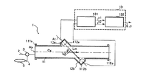
図1は、本発明の第1の実施形態に係る超音波流体計測装置(以下「計測装置」という。)1の構成を示している。本実施形態では、水素ガスを被験流体としている。
測定管11は、流量等の計測用通路を形成しており、軸方向の各端に形成されたフランジ111a,111bを介し、隣接する配管2に接続されている。配管2には、方向切換弁3が介装されており、測定管11は、この方向切換弁3により配管2と、他の配管4とに選択的に接続されるように構成されている。他の配管4には、校正流体としての窒素ガスを充填したタンク5が接続されており、タンク5内の窒素ガスを測定管11に流通させることができる。
Embodiments of the present invention will be described below with reference to the drawings.
FIG. 1 shows the configuration of an ultrasonic fluid measurement device (hereinafter referred to as “measurement device”) 1 according to a first embodiment of the present invention. In this embodiment, hydrogen gas is used as the test fluid.
The
測定管11は、管軸Apとの間に角度θを形成する軸(超音波伝搬軸Atに一致する。)を中心として、管軸方向にずれた2箇所で筒状に膨出している。このように形成される一対のトランスデューサケース112a,112bに、上流側トランスデューサ(「第1のトランスデューサ」に相当する。)12aと、下流側トランスデューサ(「第2のトランスデューサ」に相当する。)12bとが夫々収納されている。
The
これらのトランスデューサ12a,12bは、測定用超音波Wtを発生させる振動子を含んで構成され、伝搬時間算出部131及び流量演算部132を含んで構成されるコントロールユニット13に接続されている。コントロールユニット13は、各トランスデューサ12a,12bに対し、超音波Wtを発射させるための駆動信号を発生するとともに、発射された超音波Wtを受けたトランスデューサから出力された受信信号Wr1,Wr2を入力する。各トランスデューサ12a,12bは、コントロールユニット13からの駆動信号を受け、超音波伝搬線Atに沿って超音波Wtを発射する。コントロールユニット13は、入力した受信信号Wr1,Wr2をもとに、測定管11を流れる水素ガスの流量Q及び密度(濃度に相当する。)ρを算出し、出力する。出力された流量Q等は、図示しないモニタに表示される。
These
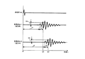
ここで、計測装置1による流量Q及び密度ρの計測原理について、図2を参照して説明する。
図2は、超音波の送信波形Wt及び受信波形Wr1,Wr2を示している。上流側トランスデューサ12aから流れに対して順方向に超音波Wtを発射した場合に得られる受信波形をWr1とし、下流側トランスデューサ12bから流れに対して逆方向に超音波Wtを発射した場合に得られる受信波形をWr2としている。超音波Wtが発射された後、受信信号(電圧で示す。)が所定のレベルVthに達する時点を受信時点tdとし、受信側のトランスデューサにより先頭の超音波(以下「先頭波」という。)が受信されてから前記受信時点tdまでの時間を検知遅れ時間trとし、超音波Wtが発射されてから先頭波が受信側のトランスデューサに到達するまでの時間を伝搬時間tとする。水素ガスの音速及び流速、並びに超音波Wtの伝搬距離をCg,Vg,Lmとすると、超音波Wtを順方向に発射したときと、超音波Wtを逆方向に発射したときとで、これらの時刻td及び時間tr,tの間には、次式(1)、(2)の関係が成り立つ。
Here, the measurement principle of the flow rate Q and the density ρ by the
FIG. 2 shows an ultrasonic transmission waveform Wt and reception waveforms Wr1 and Wr2. The received waveform obtained when the ultrasonic wave Wt is emitted in the forward direction with respect to the flow from the
td1=t1+tr1
=Lm/(Cg+Vg×cosθ)+tr1 ・・・(1)
td2=t2+tr2
=Lm/(Cg−Vg×cosθ)+tr2 ・・・(2)
流量Qを計測する場合は、(1)及び(2)式をもとに、流速Vgに関する下式(3)を得る。
td1 = t1 + tr1
= Lm / (Cg + Vg × cos θ) + tr1 (1)
td2 = t2 + tr2
= Lm / (Cg−Vg × cos θ) + tr2 (2)
When measuring the flow rate Q, the following equation (3) relating to the flow velocity Vg is obtained based on the equations (1) and (2).
Vg=[Lm/(2×cosθ)]×{1/(td1−tr1)−1/(td2−tr2)} ・・・(3)
(3)式により算出した流速Vgを次式(4)に代入し、流量Qを算出する。なお、測定管11の断面積をAとし、測定管11における流速分布補正係数をKとする。
Q=Vg×A×K ・・・(4)
他方、密度ρを計測する場合は、次式(5)により音速Cgを算出する。
Vg = [Lm / (2 × cos θ)] × {1 / (td1-tr1) −1 / (td2-tr2)} (3)
Substituting the flow velocity Vg calculated by the equation (3) into the following equation (4), the flow rate Q is calculated. The cross-sectional area of the
Q = Vg × A × K (4)
On the other hand, when measuring the density ρ, the sound velocity Cg is calculated by the following equation (5).
Cg=(Lm/2)×{1/(td1−tr1)+1/(td2−tr2)} ・・・(5)
(5)式により算出した音速Cgを次式(6)に代入し、密度ρを算出する。なお、比熱比をγとし、ガス定数をRとし、温度をTとする。
ρ=γ×{R×T/(22.4×Cg2)} ・・・(6)
なお、本実施形態では、超音波伝搬線Atを直線状に設定し、一対のトランスデューサ12a,12bを、管軸Apを基準とした測定管11の各側に配置している。しかしながら、本発明によれば、このような配置に限らず、超音波伝搬線Atを管壁上で屈曲させて設定することで、双方のトランスデューサを測定管11の片側のみに配置することもできる。
Cg = (Lm / 2) × {1 / (td1-tr1) + 1 / (td2-tr2)} (5)
The sound velocity Cg calculated by the equation (5) is substituted into the following equation (6) to calculate the density ρ. The specific heat ratio is γ, the gas constant is R, and the temperature is T.
ρ = γ × {R × T / (22.4 × Cg 2 )} (6)
In the present embodiment, the ultrasonic propagation line At is set in a straight line, and the pair of
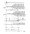
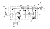
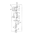
図3は、本実施形態に係るコントロールユニット13の構成を示している。コントロールユニット13の構成について、図4に示すタイムチャートを参照しつつ、図3により説明する。
方向切換部131aは、一方のトランスデューサ(例えば、上流側トランスデューサ12a)を送信用に選択するとともに、他方の下流側トランスデューサ12bを受信用に選択する。
FIG. 3 shows a configuration of the
The
駆動信号発生部131bは、送信用のトランスデューサに対する駆動信号を発生する。発生した駆動信号は、方向切換部131aを介して送信用のトランスデューサに入力され、超音波Wtが発射される(時刻t0)。駆動信号発生部131bは、駆動信号を発生するのと同時に、禁止期間設定部131c及び経過時間測定部131eに対し、計時開始信号startを出力する。
The
禁止期間設定部131cは、計測開始信号startを受けると、受信検知部131dに対し、所定の禁止期間tgに亘り受信時点の特定を禁止する受信制御信号Sgを出力する。受信制御信号Sgは、禁止期間tgにLoレベルに設定され、禁止期間tgの経過後にHiレベルに切り換えられる。受信制御信号SgがLoレベルに設定されている間、受信検知部131dによる受信時点の特定が禁止又は実質的に禁止され、受信制御信号SgがHiレベルに切り換えられることで、受信時点の特定が許可される。なお、禁止期間tgは、禁止期間記憶部131hに記憶されており、禁止期間設定部131cに読み込まれる。
When the prohibition
受信検知部131dは、方向切換部131aにより受信用に選択されたトランスデューサから受信信号Wrを入力する。ここで、受信検知部131dは、入力した受信制御信号Sgが禁止の解除を示すHiレベルに切り換えられるまで、受信信号Wrを矩形信号Sbに変換しつつ、受信時点の特定を保留する。受信検知部131dは、受信制御信号SgがHiレベルに切り換えられた後、受信時点として、変換した矩形波形Sbの最初の立ち上がり点C'を特定するとともに、特定した立ち上がり点C'において、経過時間測定部131eに対し、計時終了信号stopを出力する。なお、この立ち上がり点C'が本実施形態に係るゼロクロス点に相当する。
The
経過時間測定部131eは、計時開始信号startの入力によりタイマーを作動させるとともに、計時終了信号stopの入力によりタイマーを停止させ、経過時間としてその計時結果tdを伝搬時間算出部131fに出力する。
伝搬時間算出部131fは、入力した経過時間tdと、所定の検知遅れ時間trとをもとに、次式(7)により伝搬時間tを算出する。伝搬時間算出部131fは、算出した伝搬時間tを流量演算部132に出力する。なお、検知遅れ時間trは、検知遅れ時間記憶部131gに記憶されており、伝搬時間算出部131fに読み込まれる。検知遅れ時間trは、後述する校正処理に従い更新される。
The elapsed
The propagation
t=td−tr ・・・(7)
流量演算部132は、入力した伝搬時間tをもとに、(3)〜(6)式により水素ガスの流量Q及び密度ρを算出する。
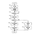
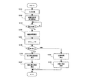
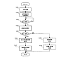
次に、コントロールユニット13の動作について、図5に示すフローチャートにより説明する。
t = td−tr (7)
The flow
Next, the operation of the
超音波流体計測装置1の電源が投入されると、このルーチンが開始され、初期設定が行われる。このルーチンは、所定の時間毎に実行される。
S101では、超音波の伝搬方向を切り換える。
S102では、送信用のトランスデューサから超音波を発射するとともに、経過時間tdの計時を開始する。
When the ultrasonic
In S101, the ultrasonic wave propagation direction is switched.
In S102, an ultrasonic wave is emitted from the transmission transducer, and the elapsed time td is started.
S103では、禁止期間tgが経過し、受信制御信号SgがHiレベルに切り換えられて、受信時点の特定が許可されたか否かを判定する。許可されないうちは、この判定を繰り返し、許可されたときは、S104へ進む。
S104では、ゼロクロス点C'を特定するとともに、特定したゼロクロス点C'の時刻tdをもとに、経過時間tdを測定する。
In S103, it is determined whether the prohibition period tg has elapsed and the reception control signal Sg has been switched to the Hi level to allow the specification of the reception time point. This determination is repeated until permission is granted, and if permission is granted, the process proceeds to S104.
In S104, the zero cross point C ′ is specified, and the elapsed time td is measured based on the time td of the specified zero cross point C ′.
S105では、校正時であるか、計測時であるかを判定する。本実施形態では、校正及び計測の切換えをスイッチにより手動で行うこととしており、スイッチの出力信号を検出して、この判定を行うようにしている。校正時には、測定管11に窒素ガスを充填し、計測時には、測定管11に水素ガスを流通させる。
S106では、窒素ガスの音速に応じた校正用伝搬時間を(1)式により算出する。なお、校正流体の流量Vgは、配管4に簡易なセンサを設置し、このセンサにより検出する。また、窒素ガスや水素ガス等の単一組成のガスを校正流体とする場合は、音速Cgは、比熱比をγとし、ガス定数をRとし、温度をTとし、モル質量をMとして、次式(8)により算出する。
In S105, it is determined whether calibration is being performed or measurement is being performed. In this embodiment, switching between calibration and measurement is manually performed by a switch, and this determination is performed by detecting an output signal of the switch. During calibration, the
In S106, the propagation time for calibration according to the sound speed of nitrogen gas is calculated by the equation (1). The flow rate Vg of the calibration fluid is detected by installing a simple sensor on the
Cg=√(γ×R×T/M) ・・・(8)
S107では、測定した経過時間tdから算出した校正用伝搬時間を減算して、検知遅れ時間trを算出する。校正では、超音波を複数回発射し、発射毎に測定した経過時間を平均して得たものを経過時間tdとするとよい。算出した検知遅れ時間trは、検知遅れ時間記憶部131gに記憶する。校正を終えると、スイッチが切り換わり、測定管11に水素ガスが流通する。
Cg = √ (γ × R × T / M) (8)
In S107, the detection delay time tr is calculated by subtracting the calculated propagation time from the measured elapsed time td. In the calibration, an elapsed time td may be obtained by emitting ultrasonic waves a plurality of times and averaging the elapsed times measured for each emission. The calculated detection delay time tr is stored in the detection delay
S108では、測定した経過時間tdから検知遅れ時間trを減算して、伝搬時間tを算出する。
S109では、算出した伝搬時間tをもとに、(3)〜(6)式により水素ガスの流量Q及び密度ρを算出する。
次に、コントロールユニット13を構成する各ブロック131a〜131hについて、詳細に説明する。
In S108, the propagation time t is calculated by subtracting the detection delay time tr from the measured elapsed time td.
In S109, based on the calculated propagation time t, the flow rate Q and the density ρ of the hydrogen gas are calculated by the equations (3) to (6).
Next, the
まず、禁止期間設定部131cについて説明する。
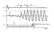
図6は、禁止期間として、受信波形Wrが定常化するまでの期間A及びBを採用した場合を示している。受信波形Wrは、トランスデューサ12a,12bの振動子の作動特性に応じ、超音波の圧力を受けて先頭波S1から周期毎に振幅が徐々に増加していき、やがて最大振幅に達して定常化する(期間C)。受信波形Wrの振幅が最大となる期間Cで受信時点(すなわち、ゼロクロス点)の特定を許可することで、本来のゼロクロス点よりも前に誤ったゼロクロス点が特定されることを回避するとともに、ゼロクロス点の特定が許可された後は、ノイズ成分Wnに対して最大のSN比が得られ、ゼロクロス点を正確に特定することができる。なお、禁止期間には、ゼロクロス点に対する余裕時間tbが設けられる。
First, the prohibition
FIG. 6 shows a case where the periods A and B until the reception waveform Wr becomes steady are adopted as the prohibition period. The reception waveform Wr receives an ultrasonic pressure and gradually increases in amplitude from the leading wave S1 in each cycle according to the operating characteristics of the
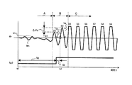
図7は、禁止期間として、受信波形の周期毎の振幅変動量ΔVs(=Vsn−Vsn-1)がノイズ成分Wnの振幅Vnよりも充分に大きくなるまでの期間Aを採用した場合を示している。先頭波S1は、ノイズ成分Wnに埋もれ、ノイズ成分Wnとの区別がつかない場合が多い。しかしながら、例えば、周期毎の振幅変動量ΔVsがノイズ成分Wnの振幅Vnの2倍以上の大きさとなるときにゼロクロス点の特定を許可することで、ノイズ成分Wnの影響を抑え、受信波形Wrが定常化する前に、早期にゼロクロス点を特定することができる。この方法によれば、計測周期を短縮することができるため、流量等の変化に対する応答性を向上させることができる。なお、ゼロクロス点に対する余裕時間tbが設けられるのは、前述同様である。 FIG. 7 shows a case where the period A until the amplitude fluctuation amount ΔVs (= Vs n −Vs n−1 ) for each period of the received waveform becomes sufficiently larger than the amplitude Vn of the noise component Wn is adopted as the prohibition period. Show. The leading wave S1 is buried in the noise component Wn and often cannot be distinguished from the noise component Wn. However, for example, by allowing the specification of the zero cross point when the amplitude fluctuation amount ΔVs for each period is twice or more the amplitude Vn of the noise component Wn, the influence of the noise component Wn is suppressed, and the received waveform Wr is reduced. The zero cross point can be identified early before the steady state. According to this method, since the measurement cycle can be shortened, responsiveness to changes in flow rate and the like can be improved. The margin time tb for the zero cross point is provided as described above.
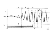
図8は、禁止期間として、以上のいずれかのものに加え、受信波形Wrが超音波伝搬線At上を伝搬した超音波以外の波との干渉により一部Wiで減衰する期間Dを採用した場合を示している。受信波形Wrの減衰の多くは、超音波伝搬線Atを外れた超音波が、測定管11の管壁で反射し、受信用のトランスデューサに入射することにより発生する。このため、測定管11の寸法や被験流体の密度等をもとに、反射伝搬波の位相遅れ時間、延いては期間Dを特定することが可能である。この方法によれば、受信波形Wrの減衰によりゼロクロス点の特定を誤るのを防止することができる。なお、ゼロクロス点に対する余裕時間tbが設けられるのは、前述同様である。
FIG. 8 employs a period D in which the received waveform Wr is partially attenuated by Wi due to interference with a wave other than the ultrasonic wave that has propagated on the ultrasonic wave propagation line At, in addition to any of the above, as the prohibition period. Shows the case. Much of the attenuation of the received waveform Wr is generated when the ultrasonic wave that has deviated from the ultrasonic wave propagation line At is reflected by the tube wall of the
以上のようにして設定した禁止期間は、禁止期間記憶部131h(図3)に記憶され、禁止期間設定部131cに読み込まれる。禁止時間設定部131cは、読み込んだ禁止期間に対し、これが経過するまでは受信制御信号SgをLoレベルに設定して、ゼロクロス点の特定を禁止し、これが経過した後は受信制御信号SgをHiレベルに切り換えて、ゼロクロス点の特定を許可する。
The prohibition period set as described above is stored in the prohibition
なお、禁止期間記憶部131hに対し、長さが異なる複数の禁止期間を予め記憶させておき、計測に際し、被験流体の種類に応じて採用する禁止期間を選択するようにしてもよい。禁止期間の選択は、操作盤に調整ダイヤルを設けたり、あるいは禁止期間毎に対応させた外部信号を発生させることにより行うことができる。外部信号には、アナログ電圧又は電流、デジタル信号、光信号、流体圧力等のいずれの形態のものを採用してもよい。外部信号による場合は、遠隔操作により禁止期間を選択することが可能となるため、微弱な電圧信号を処理する受信検知部131d等を流量演算部132及びモニタから離して設置することが可能となる。このため、計測装置1を化学プラントや放射線設備に組み込んで使用する場合に、受信検知部131d等をトランスデューサ12a,12bから近い位置に設置して、ノイズ(主に、電磁的なもの)の混入を回避し、計測精度を確保することができる。
In addition, a plurality of prohibition periods having different lengths may be stored in advance in the prohibition
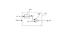
図9は、禁止期間の長さtgを可変とした場合の、禁止期間設定部131cの構成を示している。禁止期間設定部131cは、シフトレジスタc101及び減算器c102を含んで構成され、経過時間測定部131eと接続されている(図3)。順及び逆方向の各経過時間td1,td2を入力するとともに、入力した伝搬時間td1,td2をもとに、経過時間平均値ta(=(td1+td2)/2)を計測毎に算出し、シフトレジスタc101に記憶する。減算器c102は、シフトレジスタc101から前回の計測で算出された経過時間平均値tan-1を入力するとともに、入力した経過時間平均値tan-1から余裕時間tbを減算し、禁止期間の長さtg(=tan-1−tb)を算出する。禁止期間設定部131cは、設定した禁止期間に亘りLoレベルの受信制御信号Sgを出力する。以上のように禁止期間の長さtgを計測毎に調整する機能を持たせることで、ゼロクロス点C'に対し、常に一定の時間tb前に特定が許可されることになる(図4)。このため、被験流体の密度(すなわち、音速)の変化等によりゼロクロス点C'が前後したとしても、最適なタイミングで特定を許可することができる。この禁止期間設定部131cによる場合のコントロールユニット13の動作について、図10に示すフローチャートにより説明する。
FIG. 9 shows a configuration of the prohibition
図10に示すフローチャートにおいて、図5に示すものと同様な処理を行うステップには、同じ符号を付している。
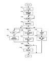
このルーチンは、電源の投入により開始され、その後、所定の時間毎に実行される。開始後、初期設定が行われるとともに、超音波の伝搬方向を切り換え(S101)、送信用のトランスデューサから超音波を発射する(S102)。禁止期間が経過して、ゼロクロス点の特定が許可されたときは(S103)、S104へ進み、ゼロクロス点C'を特定するとともに、経過時間tdを測定する。S201では、順及び逆方向のそれぞれについて測定した経過時間td1,td2を平均して、経過時間平均値taを算出し、算出した平均値ta(=tan-1)から所定の余裕時間tbを減算して、禁止期間の長さtgを算出する。経過時間平均値taは、メモリーc101に記憶され、次回の計測において、このステップで読み込まれる。校正時であるか、計測時であるかを判定し(S105)、校正時では、校正流体の音速に応じた校正用伝搬時間を算出するとともに(S106)、検知遅れ時間trを算出し、記憶する。計測時では、測定した経過時間tdから検知遅れ時間trを減算して、伝搬時間tを算出するとともに(S108)、算出した伝搬時間tをもとに、(3)〜(6)式により水素ガスの流量Q等を算出する(S109)。
In the flowchart shown in FIG. 10, steps that perform the same processing as that shown in FIG. 5 are given the same reference numerals.
This routine is started when the power is turned on, and thereafter is executed every predetermined time. After the start, initial setting is performed, the propagation direction of the ultrasonic wave is switched (S101), and the ultrasonic wave is emitted from the transmission transducer (S102). When the prohibition period has elapsed and the specification of the zero cross point is permitted (S103), the process proceeds to S104, where the zero cross point C ′ is specified and the elapsed time td is measured. In S201, the elapsed times td1 and td2 measured in each of the forward and reverse directions are averaged to calculate an elapsed time average value ta, and a predetermined margin time tb is calculated from the calculated average value ta (= tan -1 ). Subtraction is performed to calculate the length tg of the prohibition period. The elapsed time average value ta is stored in the memory c101 and read in this step in the next measurement. It is determined whether it is during calibration or measurement (S105). At the time of calibration, a calibration propagation time corresponding to the sound velocity of the calibration fluid is calculated (S106), and a detection delay time tr is calculated and stored. To do. At the time of measurement, the detection delay time tr is subtracted from the measured elapsed time td to calculate the propagation time t (S108), and based on the calculated propagation time t, hydrogen is calculated according to equations (3) to (6). The gas flow rate Q and the like are calculated (S109).
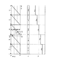
禁止期間は、以上のものに限らないが、ゼロクロス点の特定が許可される時刻tgは、被験流体の最大流量時を考慮して設定するのが好ましい。例えば、図4に符号Dで示す時点を流量がゼロであるときに特定されるゼロクロス点であるとする。ここで、流量が増大すると、これに伴い順方向について特定されるゼロクロス点Aが早まる一方、逆方向について特定されるゼロクロス点Cが遅れる。想定される最大流量時に順方向について特定されるゼロクロス点よりも前に特定が許可されるように禁止期間の長さtgを設定することで、対象とする周期以外の周期で、誤ったゼロクロス点が特定されるのを回避し、作動範囲全体に渡り流量等を正確に計測することができる。 Although the prohibition period is not limited to the above, it is preferable to set the time tg at which the specification of the zero cross point is permitted in consideration of the maximum flow rate of the test fluid. For example, it is assumed that the time point indicated by the symbol D in FIG. 4 is a zero cross point specified when the flow rate is zero. Here, when the flow rate increases, the zero cross point A specified for the forward direction is advanced accordingly, while the zero cross point C specified for the reverse direction is delayed. By setting the length tg of the prohibition period so that the specification is permitted before the zero cross point specified in the forward direction at the assumed maximum flow rate, an erroneous zero cross point in a cycle other than the target cycle Can be avoided, and the flow rate and the like can be accurately measured over the entire operating range.
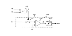
次に、受信検知部131dについて説明する。
図11は、受信検知部131dの構成を示している。受信検知部131dは、スイッチd101を含んで構成され、スイッチd101は、トランスデューサの受信信号Wrに対するゲートを構成している。受信信号Wrは、スイッチd101を介してコンパレータd102に入力される。禁止期間設定部131cには、トランスデューサの駆動信号及び禁止期間の長さtgに応じて入力状態が切り換えられるフリップフロップc102が設けられており、スイッチd101は、フリップフロップd101の出力(すなわち、受信制御信号Sg)により作動する。トランスデューサとコンパレータd102とは、受信制御信号SgがHiレベルであるときに、スイッチd101がオンして接続され、Loレベルであるときに、スイッチd101がオフして遮断される。このため、禁止期間では、コンパレータd102への受信信号Wrの入力自体が阻止されることになる。コンパレータd102は、受信波形Wrのゼロレベルを基準として、各ゼロクロス点でレベルが遷移する矩形波形Sbを出力する(図4)。禁止期間に受信信号Wrの入力が阻止されることで、コンパレータd102の出力Sbは、禁止期間が経過するまでの間、ゼロレベルを保つ。コンパレータd102の出力Sbは、単安定マルチバイブレータd103に入力され、単安定マルチバイブレータd103は、ゼロクロス点として、矩形波形Sbの最初の立ち上がり点C'を特定し、計時停止信号stopを出力する。
Next, the
FIG. 11 shows the configuration of the
なお、コンパレータd102により受信信号WrをHiレベル又はLoレベルに2値化することで、情報を単純化して、演算の効率を上げるとともに、コストを削減することができる。また、2値化の基準を受信波形Wrのゼロレベルとすることで、矩形波形Sbのレベル遷移点と、受信波形Wrのゼロクロス点とが一致するため、ゼロクロス点の特定が容易となる。 In addition, by binarizing the reception signal Wr to the Hi level or the Lo level by the comparator d102, the information can be simplified, the calculation efficiency can be improved, and the cost can be reduced. Further, by setting the binarization reference to the zero level of the reception waveform Wr, the level transition point of the rectangular waveform Sb and the zero cross point of the reception waveform Wr coincide with each other, so that the zero cross point can be easily identified.
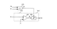
図12は、他の受信検知部131dの構成を示している。この受信検知部131dでは、トランスデューサとコンパレータd201とが、スイッチ等のゲートを介さず、直接に接続されている。このため、受信信号Wrは、常にコンパレータd201に入力される状態にあり、コンパレータd201は、受信波形Wrのゼロレベルを基準とした矩形波形Sbを出力する。禁止期間設定部131cのフロップフロップc102は、トランスデューサの駆動信号及び禁止期間の長さtgに応じた受信制御信号Sgを出力し、受信制御信号Sgは、コンパレータd201の出力とともに単安定マルチバイブレータd202に入力される。単安定マルチバイブレータd202は、矩形信号Sbの立ち上がりを迎えるたびに計時停止信号stopを内部的に発生させるが、禁止期間が経過するまでの間、受信制御信号Sgによりその出力が禁止される。このように内部的にはゼロクロス点を常に特定しながら、禁止期間ではその出力を禁止することで、禁止期間の経過後にゼロクロス点の特定を許可するのと同じ効果が得られる。
FIG. 12 shows the configuration of another
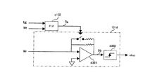
図13は、更に別の受信検知部131dの構成を示している。この受信検知部131dは、可変増幅器d301を含んで構成され、受信信号Wrの増幅率Gを第1の値G1と、これよりも大きな第2の値G2との間で切り換えることができるように構成されている。増幅率Gの大きさは、禁止期間設定部131cのフリップフロップc102から出力される受信制御信号Sgにより切り換えられ、受信制御信号SgがLoレベルであるときに第1の値G1に、Hiレベルであるときに第2の値G2に設定される。可変増幅器d301を介した受信波形Wrは、第2の値G2による場合に、単安定マルチバイブレータd302による検知が可能なほどに増幅される一方、第1の値G1による場合に、単安定マルチバイブレータd302により確実に検知されないほどに減衰する。このように増幅率Gの切換えにより禁止期間におけるゼロクロス点の特定を不能とすることで、ゼロクロス点の特定を禁止するのと同じ効果が得られる。
FIG. 13 shows a configuration of still another
図14は、更に別の受信検知部131dの構成を示している。この受信検知部131dでは、トランスデューサの受信信号Wrが常にコンパレータd401に入力される状態にあり、コンパレータd401は、単安定マルチバイブレータd402に対し、受信波形Wrのゼロレベルを基準とした矩形信号Sbを出力する。単安定マルチバイブレータd402は、矩形信号Sbの立ち上がりを迎えるたびに計時停止信号stopを発生させ、経過時間測定部131eに出力する。ここで、禁止期間設定部131cのフリップフロップc102は、トランスデューサの駆動信号及び禁止期間の長さtgに応じた計時制御信号Teを発生させ、経過時間測定部131eに出力する。計時制御信号Teは、受信制御信号Sgと同様に、禁止期間でLoレベルに、その経過後はHiレベルに設定される。経過時間測定部131eは、計時停止信号stopの入力によりタイマーを停止させ、経過時間tdを出力するが、禁止期間では、Loレベルの計時制御信号Teによりタイマーの停止が禁止される。このため、経過時間測定部131eは、計時制御信号がHiレベルに切り換えられた後にタイマーを停止させ、経過時間tdを出力する。
FIG. 14 shows a configuration of still another
次に、検知遅れ時間記憶部131gについて説明する。
検知遅れ時間記憶部131gは、校正時に算出した検知遅れ時間trを記憶する(S106,107)。記憶されている検知遅れ時間trは、計測時において、伝搬時間算出部131fに読み込まれる。
なお、校正時において、測定管11に校正流体を充填するだけとし、流量Vgをゼロとすれば、校正流体の流量Vgを検出するための特別なセンサが不要となるため、コストを削減することができる。
Next, the detection delay
The detection delay
In addition, if only the calibration fluid is filled in the measuring
また、校正時に順方向及び逆方向のそれぞれについて経過時間tdを測定し、測定した経過時間td1,td2の平均値を採用することとすれば、この平均値を流量Vgがゼロのときの経過時間とみなし、流量Vgの項を消去することができる。すなわち、この場合は、校正流体の流量Vgを検出せずに、次式(9)により検知遅れ時間trを算出することができる。 Further, if the elapsed time td is measured for each of the forward direction and the reverse direction at the time of calibration and the average value of the measured elapsed times td1 and td2 is adopted, this average value is used as the elapsed time when the flow rate Vg is zero. And the term of the flow rate Vg can be eliminated. That is, in this case, the detection delay time tr can be calculated by the following equation (9) without detecting the flow rate Vg of the calibration fluid.
tr={(td1+td2)/2}−(Lm/Cg) ・・・(9)
校正流体の音速Cgは、温度に対する依存性があり、加湿されたものでは、圧力(すなわち、湿度)に対する依存性が大きい。このため、校正流体の温度及び圧力を検出し、(8)式に対し、検出した温度Tと、圧力による補正後のモル質量Mとを代入することで、正確な校正用伝搬時間、延いては検知遅れ時間trを算出することができる。
tr = {(td1 + td2) / 2}-(Lm / Cg) (9)
The sound velocity Cg of the calibration fluid has a dependence on temperature, and when it is humidified, the dependence on pressure (that is, humidity) is large. Therefore, by detecting the temperature and pressure of the calibration fluid and substituting the detected temperature T and the molar mass M corrected by the pressure into the equation (8), an accurate calibration propagation time can be extended. Can calculate the detection delay time tr.
音速Cgが異なる複数の被験流体を対象とし、それらを交互に流通させて計測を行う場合は、次のようにして校正を簡略化することができる。
まず、(6)式を変形した次式(10)により校正流体及び被験流体の各音速Cgc,Cgmを算出する。
Cg=√{γ×R×T/(22.4×ρ)} ・・・(10)
次に、校正流体の音速Cgcに応じた校正用伝搬時間を次式(11)、(12)により算出する。
When a plurality of test fluids having different sound velocities Cg are targeted and measurement is performed by alternately circulating them, the calibration can be simplified as follows.
First, the sound velocities Cgc and Cgm of the calibration fluid and the test fluid are calculated by the following equation (10) obtained by modifying the equation (6).
Cg = √ {γ × R × T / (22.4 × ρ)} (10)
Next, the propagation time for calibration corresponding to the sound velocity Cgc of the calibration fluid is calculated by the following equations (11) and (12).
t1c=Lm/(Cgc+Vg×cosθ) ・・・(11)
t2c=Lm/(Cgc−Vg×cosθ) ・・・(12)
以上のようにして算出した音速Cgc,Cgm及び伝搬時間t1c,t2cをもとに、次式(13)、(14)により検知遅れ時間tr1,tr2を算出する。なお、記号tdは、計測時において、被験流体毎に得られる経過時間である。
t1c = Lm / (Cgc + Vg × cos θ) (11)
t2c = Lm / (Cgc−Vg × cos θ) (12)
Based on the sound velocities Cgc and Cgm and the propagation times t1c and t2c calculated as described above, the detection delay times tr1 and tr2 are calculated by the following equations (13) and (14). The symbol td is the elapsed time obtained for each test fluid at the time of measurement.
tr1=td1−t1c×Cgc/Cgm ・・・(13)
tr2=td2−t2c×Cgc/Cgm ・・・(14)
このようにすれば、校正により得られた音速Cgc及び校正用伝搬時間t1c,t2cを記憶しておくことで、被験流体を切り換えたときは、(13)、(14)式に音速Cgmを代入するだけで、簡単に検知遅れ時間trを算出することができる。また、水素ガスを被験流体とする場合は、工場等において、取扱いが容易な窒素ガスを用いて校正を済ませておき、計測プラントでは、水素ガスの音速Cgmが必要となるだけで、流通ガスの切換えを伴う校正自体は不要となり、方向切換弁3等も不要となることから、校正を簡素化し、計測装置1の安全性を向上させることができる。なお、音速Cgは、演算によるばかりでなく、別に測定して得ることもできる。
tr1 = td1−t1c × Cgc / Cgm (13)
tr2 = td2-t2c × Cgc / Cgm (14)
In this way, by storing the sonic velocity Cgc and the calibration propagation times t1c and t2c obtained by calibration, the sonic velocity Cgm is substituted into the equations (13) and (14) when the test fluid is switched. The detection delay time tr can be easily calculated simply by doing. In addition, when hydrogen gas is used as the test fluid, calibration is completed using nitrogen gas that is easy to handle in a factory or the like, and the measurement plant only requires the sonic velocity Cgm of the hydrogen gas. Since calibration with switching is not necessary and the
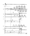
ところで、検知遅れ時間trは、既述の通り、ゼロクロス点までの経過時間tdから伝搬時間tを減じた時間に相当する(図4)。言い換えると、検知遅れ時間trは、受信用のトランスデューサに先頭波S1が到達してから検知対象波(ここでは、S6)が到達するまでの時間であり、ゼロクロス点を受信波形Wrの立ち上がり時に特定する場合は、超音波の周期Tpの整数倍に相当する。他方、ゼロクロス点を受信波形Wrの立ち下がり時に特定する場合は、超音波の半周期(=Tp/2)の整数倍に相当する。先頭波Sの到達から検知対象波S6の到達までの周期数が判明している場合は、この関係をもとに、検知遅れ時間trを予め設定することができる。図4の例では、この周期数が5であるから、超音波の周波数を40kHzとすると、検知遅れ時間trは、125μs(=Tp×5=25μs×5)となる。 By the way, as described above, the detection delay time tr corresponds to a time obtained by subtracting the propagation time t from the elapsed time td until the zero cross point (FIG. 4). In other words, the detection delay time tr is the time from the arrival of the leading wave S1 to the receiving transducer until the detection target wave (S6 in this case) arrives, and the zero cross point is specified at the rise of the reception waveform Wr. This corresponds to an integral multiple of the ultrasonic cycle Tp. On the other hand, when the zero-cross point is specified at the fall of the reception waveform Wr, it corresponds to an integral multiple of the ultrasonic half-cycle (= Tp / 2). When the number of periods from the arrival of the leading wave S to the arrival of the detection target wave S6 is known, the detection delay time tr can be set in advance based on this relationship. In the example of FIG. 4, since the number of periods is 5, when the ultrasonic frequency is 40 kHz, the detection delay time tr is 125 μs (= Tp × 5 = 25 μs × 5).
tr=n×Tp ・・・(15a)
tr=n×(1/2)×Tp ・・・(15b)
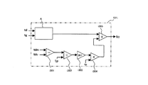
次に、本発明の他の実施形態について説明する。
図15は、本実施形態に係る計測装置のうち、コントロールユニット13の構成を示している。同図において、先の実施形態のものと同様に動作するブロックには、図3におけると同じ符号を付している。なお、測定管11、トランスデューサ12a,12b等、コントロールユニット13以外の要素は、先の実施形態のものと同様である。
tr = n × Tp (15a)
tr = n × (1/2) × Tp (15b)
Next, another embodiment of the present invention will be described.
FIG. 15 shows the configuration of the
コントロールユニット13は、受信時点補正部131iを更に含んで構成される。受信時点補正部131iは、経過時間tdの変化に後述する折り返し(以下、単に「折り返し」という。)が生じたことで、1周期以上の誤差を含んでゼロクロス点を特定した場合に、この誤差を補償する。受信時点補正部131iは、経過時間測定部131eから経過時間tdを入力するとともに、禁止期間設定部131cから禁止期間の長さtgを入力し、これらの情報をもとに、折り返しが生じたことを検出し、折り返しが発生したときは、その方向に応じた周期補正量tcを算出し、伝搬時間算出部131fに出力する。伝搬時間算出部131fは、経過時間td、検知遅れ時間tr及び入力したtcをもとに、次式(16)により伝搬時間tを算出する。
The
t=td−(tr−tc) ・・・(16)
ここで、経過時間tdの変化に生じる折り返しについて、図16に示すタイムチャートにより説明する。同図において、受信波形Wrは、順方向に超音波を発射した場合のものを示している。
受信波形Wrのうち、4周期目の波S4を対象とし、その減少方向のゼロクロス点Fを特定する場合を考える。まず、1回目の計測において、受信制御信号Sgが4周期目の波S4に対応する点HでHiレベルに切り換えられ、ゼロクロス点Fの特定が許可されている。矩形波形Sbは、許可が下りるとともにHiレベルに遷移し、その後のゼロクロス点FでLoレベルに遷移している。このため、矩形波形Sbのうち、最初の立ち下がり点Iを検出することで、正しいゼロクロス点Fを特定することができる。次の計測では、流量Qが増大し、受信波形Wrの位相が点線で示すように早まっているとする。流量Qが増大する場合は、その変化量に応じて経過時間tdが短くなるのが通常である。ところが、流量Qの変化が急激であり、受信制御信号SgがHiレベルに切り換えられる点Hが本体のゼロクロス点F'よりも遅くなったとすると、4周期目の波S4に対応する点Hでゼロクロス点の特定が許可されるものの、矩形波形Sbの最初の立ち下がり点Jは、次の5周期目の波S5に対応することとなるため、測定された経過時間td'に1周期分の誤差が含まれることになる。このように経過時間tdが本来の方向とは逆に変化することを、折り返しという。
t = td− (tr−tc) (16)
Here, the folding that occurs when the elapsed time td changes will be described with reference to the time chart shown in FIG. In the figure, a received waveform Wr shows a case where ultrasonic waves are emitted in the forward direction.
Consider a case where the zero-cross point F in the decreasing direction is specified for the wave S4 in the fourth period of the received waveform Wr. First, in the first measurement, the reception control signal Sg is switched to the Hi level at the point H corresponding to the wave S4 in the fourth period, and the specification of the zero cross point F is permitted. The rectangular waveform Sb changes to the Hi level when permission is given, and then changes to the Lo level at the zero cross point F thereafter. For this reason, the correct zero cross point F can be specified by detecting the first falling point I in the rectangular waveform Sb. In the next measurement, it is assumed that the flow rate Q increases and the phase of the received waveform Wr is advanced as indicated by a dotted line. When the flow rate Q increases, the elapsed time td is usually shortened according to the amount of change. However, if the flow rate Q changes rapidly and the point H at which the reception control signal Sg is switched to the Hi level is later than the zero cross point F ′ of the main body, the zero cross at the point H corresponding to the wave S4 in the fourth period. Although the specification of the point is permitted, the first falling point J of the rectangular waveform Sb corresponds to the next wave S5 of the fifth cycle, and therefore an error of one cycle is measured in the measured elapsed time td ′. Will be included. Such a change in the elapsed time td opposite to the original direction is referred to as folding.
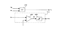
図17は、受信時点補正部131iの構成を示している。減算器i101は、経過時間td及び禁止期間の長さtgを入力し、これらの差tm(=td−tg)を算出する。この差tmは、受信制御信号SgがHiレベルに切り換えられてからゼロクロス点が特定されるまでの時間である(図16)。差tmは、シフトレジスタi102に記憶される。減算部i103は、差tmと、シフトレジスタi102に記憶されている、前回の計測で算出された差tmn-1とを入力し、これらの差Dtm(=tm−tmn-1)を算出する。なお、シフトレジスタi102に、前回までに算出された所定の数nの差tmを記憶させておき、減算部i103に対し、それらの平均値(=Σtm/n)又は最頻値が出力されるようにしてもよい。除算器i104は、差Dtmを超音波の周期tpで除算し、差Dtmを、周期tpを基準とした差tmの変化率Xに変換する。比較器i105は、変化率Xが所定の値SRよりも大きいか否かを判定し、大きいときは、1を出力して折り返しが生じたことを示し、小さいときは、0を出力する。所定の値SRは、流量Qの変化の速さと、計測の実行間隔とから決定される。受信波形Wrに1周期分のズレを与える流量Qの変化が1秒をかけて行われ、計測の実行間隔が0.1秒である場合は、流量Qの変化が時間に対して直線的に変化するとすれば、差tm(すなわち、経過時間td)は0.1(=1×0.1)の割合で変化することになり、この0.1を超える変化率Xが算出されたときは、折り返しが生じたものと判断することができる。また、所定の値SRは、ノイズによる変動分を考慮し、想定される最大変化率よりも若干大きな値に設定するとよい。折り返しの検出と並行して、符号判定器i106は、差Dtmをその絶対値で除算し、経過時間tdの変化の方向を判定する。符号判定器i106は、経過時間tdが短くなる場合に“−”を、経過時間が長くなる場合に“+”を出力する。乗算器i107は、比較器i105の出力に符号判定器i106の出力を乗算し、折り返しに対する補正の要否を判定する。すなわち、乗算器i107の出力が0のときは、補正が不要であることを示し、−1又は1であるときは、補正が必要であることを示す。なお、−1又は1の符号は、補正の方向を示す。加算器i108は、乗算器i107の出力に前回の計測で使用した周期補正量Nn-1を加算し、今回の周期補正量Nを算出する。周期補正量Nは、シフトレジスタi109に記憶され、次回の計測において、加算部i108に読み込まれる。前回の周期補正量Nn-1を加算することで、折り返しが複数回生じた場合に対応することができる。乗算器i110は、周期補正量Nに周期tpを乗算し、時間を単位とする周期補正量tcを算出する。周期補正量tcは、伝搬時間算出部131fに出力される。
FIG. 17 shows a configuration of the reception
本実施形態に関し、変化率Xは、受信制御信号SgがHiレベルに切り換えられたときを基準時点とした場合の「第2の変動率」に相当する。
図18は、他の受信時点補正部131iの構成を示している。減算器i201は、経過時間td及び禁止期間の長さtgを入力し、これらの差tm(=td−tg)を算出する。
Regarding the present embodiment, the rate of change X corresponds to a “second variation rate” when the time when the reception control signal Sg is switched to the Hi level is set as the reference time point.
FIG. 18 shows a configuration of another reception
ここで、差tmについて、図19により説明する。
図19は、本来のゼロクロス点Fの時刻tsに対する差tmの変化を示すタイムチャートである。差tmは、時刻tsに応じ、0から超音波の周期tpの間で変化する。既述の通り、流量Qの増大等により受信波形Wrの位相が早まり、本来のゼロクロス点Fの時刻tsが早まると、経過時間tdと禁止期間の長さtgとの差tmは、時刻tsの変化に比例して小さくなる。時刻tsが大きく変化し、ゼロクロス点Fが点Hよりも前の時点となると、波s4を対象としてゼロクロス点F'を特定することができなくなり、次の波s5のゼロクロス点Gが特定されることになる(図16)。このため、差tmは、点Hの時刻tgで0からtpに切り換わり、時刻tpの減少に応じて更に変化することとなるため、結果として、時刻tsに対して鋸歯状の波形を描くこととなる。ここで、本来のゼロクロス点が点Fから点F'に遷移した場合を考えると、ゼロクロス点Fの変化とともに差tmがtm1からtm2に変化することとなるが(図16)、その変化の過程で、時刻tgにおいて、差tmがtpに切り換わり、経過時間tdが本来の方向とは逆に変化する折り返しが生じることになる(図19)。以下、本来のゼロクロス点が点Fから点F'に遷移した場合を例に説明する。
Here, the difference tm will be described with reference to FIG.
FIG. 19 is a time chart showing the change of the difference tm with respect to the time ts of the original zero cross point F. The difference tm varies between 0 and an ultrasonic cycle tp according to the time ts. As described above, when the phase of the received waveform Wr is advanced due to an increase in the flow rate Q and the time ts of the original zero cross point F is advanced, the difference tm between the elapsed time td and the length tg of the prohibited period is the time ts. It becomes smaller in proportion to the change. When the time ts changes greatly and the zero cross point F comes before the point H, the zero cross point F ′ cannot be specified for the wave s4, and the zero cross point G of the next wave s5 is specified. (FIG. 16). For this reason, the difference tm switches from 0 to tp at the time tg of the point H and further changes in accordance with the decrease in the time tp. As a result, a sawtooth waveform is drawn with respect to the time ts. It becomes. Here, considering the case where the original zero cross point has transitioned from the point F to the point F ′, the difference tm changes from tm1 to tm2 as the zero cross point F changes (FIG. 16). Thus, at time tg, the difference tm is switched to tp, and a turn-back occurs in which the elapsed time td changes in the opposite direction to the original direction (FIG. 19). Hereinafter, an example in which the original zero cross point transitions from the point F to the point F ′ will be described.
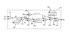
図18に戻り、区間判定器i202は、差tmが0〜tpの範囲のいずれの区間に属するかを判別する。例えば、0〜tpの範囲を3つの区間に等分し、差tmが区間1〜3のいずれに属するかを判別する。今回の計測で本来のゼロクロス点が点F'にあるとすると、差tm(=tm2)が属する区間Kは、3となる。判別された区間K(=1〜3)は、シフトレジスタi203に記憶される。シフトレジスタi203は、前回に判別された区間Kn-1又は前回までに判別された少なくとも1つの区間を記憶している。減算器i204は、区間Kを入力するとともに、シフトレジスタi203から前回に判別された区間Kn-1を入力し、これらの差(=K−Kn-1)を算出する。なお、前回の計測で本来のゼロクロス点は点Fにあるから、差tmはtm1であり、区間Kn-1は1である。減算器i204に対し、シフトレジスタi203から記憶されている区間Kの平均値(=ΣK/n)又は最頻値が出力されるようにしてもよい。等号比較器i205は、区間差が2であるか否かを判定する。2であるときは、折り返しが生じたとして1を出力し、2でないときは、折り返しは生じていないとして0を出力する。なお、区間の分割数や幅は、特に限定されるものではなく、流量Qの変化の速さや計測の実行間隔等に応じ、適宜に設定することができる。分割数として3以外のものを採用した場合の判定値は、「分割数-1」である。折り返しの有無を判定するのと並行して、符号判定器i205は、折り返しの方向を判定する。すなわち、符号判定器i205は、区間差と0とを比較し、区間差が0よりも大きいとき(経過時間tdが増大する折り返しが生じたとき)に1を、区間差が0以下であるときに−1を出力する。乗算器i207は、等号比較器i205の出力と、符号判定器i206の出力とを乗算し、周期補正量の加算値Nを算出する。加算値Nが0であるときは、折り返しに対する補正が不要であり、加算値Nが−1又は1であるときは、この補正が必要であることを示す。加算器i208は、加算値Nに前回の計測で使用した周期補正量Nn-1を加算し、今回の周期補正量Nを算出する(図19)。周期補正量Nは、シフトレジスタi209に記憶され、次回の計測で加算部i208に読み込まれる。乗算器i210は、周期補正量Nに周期tpを乗算し、時間を単位とする周期補正量tcを算出する。周期補正量tcは、伝搬時間算出部131fに出力される。
Returning to FIG. 18, the section determiner i202 determines which section in the range of the
本実施形態に関し、区間差(=K−Kn-1)は、受信制御信号SgがHiレベルに切り換えられたときを基準時点とした場合の「第2の変動率」に相当する。
図20は、更に別の受信時点補正部131iの構成を示している。この受信時点補正部131iは、以上で述べた受信時点補正部Aに対し、ブロックi301〜i305を付加したものである。減算器i301は、校正時に得られた経過時間tdcと、計測開始時に得られる経過時間tdmとを入力し、これらの差Dtd(=tdm−tdc)を算出する。除算器i302は、差Dtdを入力し、超音波の周期tpで除算する。整数変換器i303は、その商(=Dtd/tp)を入力し、1未満の位を切り捨てた整数値に変換する。乗算器i304は、この整数値に周期tpを乗算し、時間を単位とする初期補正量tc0を算出する。加算器i305は、ブロックAから出力された周期補正量tcに初期補正量tc0を加算し、これを最終的な周期補正量として伝搬時間算出部131fに出力する。この受信時点補正部131iにすれば、ブロックAにより経過時間の折り返しが補償されることに加え、校正ガスと被験ガスとで音速が大きく異なり、校正により設定された検知遅れ時間tcに超音波の1周期を超える誤差が含まれるとしても、これを補償し、計測当初から伝搬時間tを正確に測定することができる。なお、初期補正量tc0の符号は、校正ガスの音速に比べ、被験ガスの音速が大きいときは“−”であり、小さいときは“+”である。
In the present embodiment, the section difference (= K−K n−1 ) corresponds to a “second variation rate” when the reference time is set when the reception control signal Sg is switched to the Hi level.
FIG. 20 shows the configuration of still another reception
本実施形態に関し、商(=Dtd/tp)は、校正時に特定された受信時点に対する「第1の変動率」に相当する。
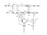
図21は、計測装置1を設置した燃料電池システムの構成を示している。
燃料電池6は、アノード側で燃料ガス供給管7a及び燃料ガス排出管7bと接続される一方、カソード側で酸化ガス供給管8a及び酸化ガス排出管8bと接続されている。燃料電池6には、燃料ガス供給管7aを介して水素ガスが供給され、酸化ガス供給管8aを介して空気が供給される。燃料ガス供給管7aと燃料ガス排出管7bとは、燃料ガス戻し管7cにより接続されており、アノードからの排出ガスの一部が燃料ガス供給管7aに戻されるように構成されている。戻される排出ガスの流量は、分岐部7dの下流に設置された流量制御弁9により調節される。流量制御弁9は、燃料電池6のコントロールユニット(以下「燃料電池C/U」という。)101により開度が制御される。分岐部7dの上流には、計測装置1が介装されており、計測装置1のコントロールユニット(以下「計測装置C/U」という。)13は、計測した排出ガスの流量Q及び密度ρを燃料電池C/U101に出力する。燃料電池C/U101は、入力した流量Q、密度ρ及び他の情報をもとに、流量制御弁9の開度を演算する。燃料ガス排出管7bには、計測装置1のほか、燃料ガス排出管7b内の圧力を検出する圧力センサ105、排出ガスの湿度を検出する湿度センサ106、及び排出ガスの温度を検出する温度センサ107が設置されており、これらの検出信号は、計測装置C/U13に出力される。計測装置C/Uは、トランスデューサ12a,12bの受信信号Wr及び入力した圧力等をもとに、排出ガスの流量Q及び密度ρを演算する。なお、燃料電池C/U101には、システム起動用のスイッチ102が設けられ、計測装置C/U13には、計測装置1のスイッチ135が設けられている。後者のスイッチ135は、計測装置C/U13からの指令信号により作動する。
In this embodiment, the quotient (= Dtd / tp) corresponds to the “first variation rate” with respect to the reception time point specified at the time of calibration.
FIG. 21 shows the configuration of the fuel cell system in which the
The
図22は、計測装置C/U13の動作を示すフローチャートである。
システム起動用のスイッチ102にオンされと、これに連動してスイッチ135がオンされ、このルーチンが開始される。このルーチンは、所定の時間毎に実行される。このシステムでは、停止時において、燃料ガス供給管7a及び燃料ガス排出管7bに窒素ガスが充填される。スイッチ102がオンされると、このルーチンにより校正が行われ、検知遅れ時間trが更新される。更新が終了すると、燃料ガス供給管7aに水素ガスが供給されて、管内のガスが水素ガスに切り換えられ、燃料電池6の運転が開始される。燃料電池6の運転時において、計測装置1は、排出ガスの流量Q等を計測する。なお、スイッチ102を操作盤に設け、校正と計測との切換えを手動で行うようにしてもよい。
FIG. 22 is a flowchart showing the operation of the measuring apparatus C / U13.
When the
S101〜104では、図5に示すフローチャートにおけると同様に超音波の伝搬方向を切り換え(S101)、送信用のトランスデューサから超音波を発射し(S102)、ゼロクロス点の特定が許可されたか否かを判定し(S103)、これが許可されたときにゼロクロス点C'を特定して、経過時間tdを測定する(S104)。
S301では、校正が終了しているか否かを判定する。スイッチ135がオンされた直後であり、校正が終了していないときは、S106へ進み、図5に示すフローチャートにおけると同様に校正用伝搬時間を算出し(S106)、検知遅れ期間trを算出し、更新する(S107)。校正が終了し、燃料電池6の運転が開始されているときは、S108ヘ進み、伝搬時間tを測定し(S108)、流量Q等を演算する(S109)。
In S101 to 104, the ultrasonic wave propagation direction is switched (S101) as in the flowchart shown in FIG. 5, and the ultrasonic wave is emitted from the transmission transducer (S102). A determination is made (S103), and when this is permitted, the zero cross point C ′ is specified, and the elapsed time td is measured (S104).
In S301, it is determined whether or not calibration is completed. If the calibration is not completed immediately after the
このようにすれば、システムを起動するたびに受信遅れ時間trの校正を行うことができるため、トランスデューサ12a,12bや計測装置F/C13等の回路系に経時変化が生じたとしても、これを補償し、精度を維持することができる。
なお、システムを起動する際に、校正の終了を待たずに水素ガスの供給を開始し、水素ガスにより校正を行うこととしてもよい。この場合は、校正時に加湿を行わず、乾燥した純粋な水素ガスを燃料ガス排出管7bに充填又は流通させることで、校正ガスの音速Cgcを正確に算出することができる。このようにすれば、校正が終了した後、燃料電池6の運転を開始させる際に、管内が水素ガスに既に切り換えられている状態にあるため、燃料電池6からの出力を早期に得ることができる。
In this way, since the reception delay time tr can be calibrated every time the system is started, even if a change over time occurs in the circuit systems such as the
When starting up the system, the supply of hydrogen gas may be started without waiting for the end of calibration, and calibration may be performed using hydrogen gas. In this case, the sonic velocity Cgc of the calibration gas can be accurately calculated by filling or circulating dry pure hydrogen gas in the fuel
また、計測装置C/U13には、次のように故障診断機能を付加することもできる。
図23は、故障診断機能を備える計測装置C/U13の動作を示すフローチャートである。このルーチンは、システム起動用のスイッチ135がオンされることにより開始され、所定の時間毎に実行される。このルーチンでは、故障診断機能によりアノード側の配管(測定管11、燃料ガス供給管7a及び燃料ガス排出管7bを含む。)に生じた漏れを検知し、運転者にその認識を促す。
Further, a failure diagnosis function can be added to the measuring device C /
FIG. 23 is a flowchart showing the operation of the measurement apparatus C /
S101〜104では、図5に示すフローチャートにおけると同様の処理を行い、経過時間tdを測定する。
S401では、システムの運転状態を判定する。起動時はS106へ、運転時はS108へ、停止時はS402へ進む。
停止時において、S402では、加湿を停止するとともに、校正時と同じ水素ガスの流量が得られる状態に設定し、管内の流れが定常化するまで待機する。定常化したときは、S403へ進む。定常化したか否かは、流量Q又は密度ρを算出するとともに、その演算周期毎の変化量と所定の値とを比較することで、判定することができる。また、燃料ガス排出管7b内の温度、圧力又は湿度の経時変化を監視したり、スイッチ135がオフされてからの時間を監視することで、簡易に判定することもできる。
In S101-104, the same process as in the flowchart shown in FIG. 5 is performed, and the elapsed time td is measured.
In S401, the operating state of the system is determined. When starting, the process proceeds to S106, during operation, the process proceeds to S108, and when stopped, the process proceeds to S402.
At the time of stoppage, in S402, the humidification is stopped and the flow rate of hydrogen gas same as that at the time of calibration is set so that the flow in the pipe becomes steady. When it becomes steady, the process proceeds to S403. Whether or not it has become steady can be determined by calculating the flow rate Q or the density ρ and comparing the amount of change for each calculation cycle with a predetermined value. Further, it can be easily determined by monitoring a change in temperature, pressure or humidity in the fuel
S403では、伝搬時間tを測定し、これを停止時伝搬時間として記憶する。その後、スイッチ135がオフされ、計測装置1が電源から遮断される。
起動時において、S106,107では、図5に示すフローチャートを同様の処理を行い、校正用伝搬時間及び検知遅れ時間trを算出し、これを記憶する。
S404では、停止時伝搬時間と校正用伝搬時間との間に所定の値以上の差があるか否かを判定する。差があるときは、S405に進み、差がないときは、このルーチンをそのまま終了する。
In S403, the propagation time t is measured and stored as the stop time propagation time. Thereafter, the
At start-up, in S106 and 107, the same processing as the flowchart shown in FIG. 5 is performed, and the calibration propagation time and detection delay time tr are calculated and stored.
In S404, it is determined whether or not there is a difference of a predetermined value or more between the stop time propagation time and the calibration propagation time. If there is a difference, the process proceeds to S405, and if there is no difference, this routine is ended as it is.
S405では、漏れの発生を検知したとして、警報を作動させる。
以上に述べたように、本発明によれば、超音波が発射された後、禁止期間が経過するまではゼロクロス点の特定を禁止し、その後にゼロクロス点を特定するようにしたので、ノイズ等の影響で、本来のゼロクロス点よりも前に誤ったゼロクロス点が特定されるのを防止することができる。
In S405, an alarm is activated on the assumption that leakage has occurred.
As described above, according to the present invention, after the ultrasonic wave is emitted, the zero cross point is prohibited until the prohibition period elapses, and then the zero cross point is specified. As a result, it is possible to prevent an erroneous zero cross point from being specified before the original zero cross point.
また、このようにゼロクロス点の特定に対するノイズの影響を排除することができるので、ゼロクロス点の特定に関する所定のレベルVthの大きさを適正なものとし、かつこのレベルVthとの比較において、ある程度大きな振幅を持つ超音波成分を採用することが可能となるので、良好なSN比によりゼロクロス点を正確、かつ確実に特定することができる。 In addition, since the influence of noise on the specification of the zero cross point can be eliminated in this way, the magnitude of the predetermined level Vth relating to the specification of the zero cross point is made appropriate, and is somewhat large in comparison with this level Vth. Since an ultrasonic component having an amplitude can be employed, the zero cross point can be accurately and reliably specified with a good S / N ratio.
1…超音波流体計測装置、11…測定管、12a,12b…トランスデューサ、13…計測装置C/U、131…伝搬時間算出部、132…流量演算部、3…方向切換弁、5…校正ガスタンク、6…燃料電池、7a…燃料ガス供給管、7b…燃料ガス排出管、7c…燃料ガス戻し管、8a…酸化ガス供給管、8b…酸化ガス排出管、9…流量制御弁、101…燃料電池C/U、105…圧力センサ、106…湿度センサ、107…温度センサ。
DESCRIPTION OF
Claims (25)
測定管を横断させて設定した超音波伝搬線上に設置され、流れに対して順方向に超音波を発射する第1のトランスデューサと、
超音波伝搬線上に、第1のトランスデューサよりも下流に設置され、流れに対して逆方向に超音波を発射する第2のトランスデューサと、
第1又は第2のトランスデューサから発射された超音波を受信したトランスデューサの出力が所定のレベルに達する時点を受信時点として特定する受信時点特定手段と、
特定された受信時点をもとに、第1又は第2のトランスデューサから発射された超音波の、受信側のトランスデューサまでの各伝搬時間を測定する伝搬時間測定手段と、
測定された各伝搬時間をもとに、被験流体に関する所定の演算を行う演算手段と、
第1又は第2のトランスデューサから超音波が発射された後、所定の時間が経過するまでの禁止期間において、受信時点特定手段による受信時点の特定を禁止する受信時点特定禁止手段と、を含んで構成される超音波流体計測装置。 A measuring tube for circulating the test fluid;
A first transducer installed on an ultrasonic propagation line set across the measuring tube and emitting ultrasonic waves in a forward direction with respect to the flow;
A second transducer disposed on the ultrasonic propagation line downstream of the first transducer and emitting ultrasonic waves in a direction opposite to the flow;
Reception time specifying means for specifying, as a reception time, a time when the output of the transducer that has received the ultrasonic wave emitted from the first or second transducer reaches a predetermined level;
Propagation time measuring means for measuring each propagation time of the ultrasonic wave emitted from the first or second transducer to the receiving-side transducer based on the specified reception time point;
Based on each measured propagation time, calculation means for performing a predetermined calculation on the test fluid;
Reception time specification prohibiting means for prohibiting reception time specifying means from specifying the reception time in a prohibition period until a predetermined time elapses after the ultrasonic wave is emitted from the first or second transducer. Constructed ultrasonic fluid measuring device.
伝搬時間測定手段は、測定管に校正流体が流通し又は充填されているときに特定される受信時点及び送信時点の間の時間と、校正流体の音速をもとに得られる校正用伝搬時間との差を算出する手段と、算出した差を検知遅れ時間として記憶する手段と、を含んで構成される請求項2に記載の超音波流体計測装置。 The measurement tube is configured to be able to circulate or fill a calibration fluid whose sound velocity is known instead of the test fluid,
The propagation time measurement means includes a time between a reception time point and a transmission time point specified when the calibration fluid is flowing or filled in the measurement tube, and a calibration propagation time obtained based on the sound velocity of the calibration fluid. The ultrasonic fluid measurement apparatus according to claim 2, comprising: means for calculating the difference between the two and means for storing the calculated difference as a detection delay time.
測定管内の流れが定常状態にあると判定されたときに伝搬時間測定手段により測定された伝搬時間と、校正用伝搬時間とをもとに、測定管からの流体の漏れを検出する手段と、を更に含んで構成される請求項4〜8のいずれかに記載の超音波流体計測装置。 Means for determining that the flow in the measurement tube is in a steady state under conditions for obtaining a predetermined flow rate of the test fluid;
Means for detecting fluid leakage from the measurement tube based on the propagation time measured by the propagation time measurement means when the flow in the measurement tube is determined to be in a steady state, and the propagation time for calibration; The ultrasonic fluid measuring device according to claim 4, further comprising:
受信時点特定禁止手段に対し、第1及び第2の時間の間で前記所定の時間を切り換えて設定する手段を更に含んで構成される請求項1〜12のいずれかに記載の超音波流体計測装置。 As the predetermined time, a first time and a second time longer than this are set,
The ultrasonic fluid measurement according to claim 1, further comprising means for switching and setting the predetermined time between the first time and the second time with respect to the reception time point specification prohibiting means. apparatus.
受信時点特定禁止手段は、前記所定の時間が経過する前後で前記増幅率を切り換え、経過前に第1の増幅率を、経過後に第2の増幅率を設定する請求項1〜17のいずれかに記載の超音波流体計測装置。 As the amplification factor of the transducer output, a first amplification factor and a second amplification factor larger than this are set,
18. The reception time point specification prohibiting unit switches the amplification factor before and after the predetermined time has elapsed, and sets the first amplification factor before the passage and the second amplification factor after the passage. The ultrasonic fluid measuring device according to 1.
Priority Applications (1)
| Application Number | Priority Date | Filing Date | Title |
|---|---|---|---|
| JP2003422003A JP2005181097A (en) | 2003-12-19 | 2003-12-19 | Ultrasonic fluid measuring device |
Applications Claiming Priority (1)
| Application Number | Priority Date | Filing Date | Title |
|---|---|---|---|
| JP2003422003A JP2005181097A (en) | 2003-12-19 | 2003-12-19 | Ultrasonic fluid measuring device |
Publications (1)
| Publication Number | Publication Date |
|---|---|
| JP2005181097A true JP2005181097A (en) | 2005-07-07 |
Family
ID=34783003
Family Applications (1)
| Application Number | Title | Priority Date | Filing Date |
|---|---|---|---|
| JP2003422003A Withdrawn JP2005181097A (en) | 2003-12-19 | 2003-12-19 | Ultrasonic fluid measuring device |
Country Status (1)
| Country | Link |
|---|---|
| JP (1) | JP2005181097A (en) |
Cited By (3)
| Publication number | Priority date | Publication date | Assignee | Title |
|---|---|---|---|---|
| WO2008149868A1 (en) * | 2007-05-31 | 2008-12-11 | Teijin Pharma Limited | Ultrasonic gas concentration measuring method and device using the same |
| CN103874920A (en) * | 2011-10-06 | 2014-06-18 | 韦斯全球有限公司 | Exterior wall-coupling type ultrasound system for measuring density and method for same |
| CN110068387A (en) * | 2018-01-24 | 2019-07-30 | 安东帕有限责任公司 | The method for determining the correction value of the velocity of sound for depending on viscosity in liquid to be checked |
-
2003
- 2003-12-19 JP JP2003422003A patent/JP2005181097A/en not_active Withdrawn
Cited By (8)
| Publication number | Priority date | Publication date | Assignee | Title |
|---|---|---|---|---|
| WO2008149868A1 (en) * | 2007-05-31 | 2008-12-11 | Teijin Pharma Limited | Ultrasonic gas concentration measuring method and device using the same |
| JP4988839B2 (en) * | 2007-05-31 | 2012-08-01 | 帝人ファーマ株式会社 | Ultrasonic gas concentration measuring method and apparatus using the same |
| US8746037B2 (en) | 2007-05-31 | 2014-06-10 | Teijin Pharma Limited | Ultrasonic apparatus and method for measuring the concentration of gas |
| CN103874920A (en) * | 2011-10-06 | 2014-06-18 | 韦斯全球有限公司 | Exterior wall-coupling type ultrasound system for measuring density and method for same |
| JP2014528582A (en) * | 2011-10-06 | 2014-10-27 | ウェス グローバル インコーポレーテッドWess Global, Inc. | Clamp-on type ultrasonic concentration measurement system and method |
| CN110068387A (en) * | 2018-01-24 | 2019-07-30 | 安东帕有限责任公司 | The method for determining the correction value of the velocity of sound for depending on viscosity in liquid to be checked |
| JP2019128356A (en) * | 2018-01-24 | 2019-08-01 | アントン パール ゲゼルシャフト ミット ベシュレンクテル ハフツングAnton Paar GmbH | Method for determining corrected value for viscosity-dependent sonic velocity in fluid to be tested |
| JP7292885B2 (en) | 2018-01-24 | 2023-06-19 | アントン パール ゲゼルシャフト ミット ベシュレンクテル ハフツング | Method for determining correction values for viscosity-dependent acoustic velocity in fluid under test |
Similar Documents
| Publication | Publication Date | Title |
|---|---|---|
| US6625549B1 (en) | Equipment specifying system | |
| CN104105952B (en) | Apparatus and method for correcting offset | |
| JP3732642B2 (en) | Ultrasonic liquid level measuring device | |
| JP2005241546A (en) | Doppler ultrasonic flowmeter, processing device thereof and program | |
| US10564017B2 (en) | Ultrasonic flowmeter and method using partial flow measurements | |
| JP2007187506A (en) | Ultrasonic flowmeter | |
| US6766276B1 (en) | Method and device for detecting a dysfunction of an ulatrasonic flowmeter | |
| JP2005181097A (en) | Ultrasonic fluid measuring device | |
| JP5123469B2 (en) | Ultrasonic flow meter | |
| JP5434548B2 (en) | Flow velocity distribution measuring method and flow velocity distribution measuring apparatus | |
| JP2006308439A (en) | Flow measuring device of fluid | |
| US20220074773A1 (en) | Method for Operating an Ultrasonic Flowmeter and Ultrasonic Flowmeter | |
| JP2005345256A (en) | Ultrasonic fluid measuring apparatus | |
| JP3469405B2 (en) | Temperature measurement device | |
| JP2007240220A (en) | Ultrasonic fluid measuring apparatus | |
| JPH08271322A (en) | Ultrasonic liquid level measuring method | |
| JP2007192763A (en) | Autonomous travel device | |
| JPS5826239A (en) | Detecting method for liquid leakage position | |
| JP2007024681A (en) | Ultrasonic fluid measuring device | |
| JP2010145213A (en) | Device of measuring flow velocity or flow rate | |
| US20210010840A1 (en) | Method of measuring the speed of a fluid | |
| JP2009031134A (en) | Ultrasonic flowmeter | |
| KR20240095425A (en) | gas concentration measuring device | |
| JP2001242000A (en) | Ultrasonic level meter | |
| EP4092393A1 (en) | Ultrasonic flow meter with estimation of a flow rate distribution |
Legal Events
| Date | Code | Title | Description |
|---|---|---|---|
| A621 | Written request for application examination |
Free format text: JAPANESE INTERMEDIATE CODE: A621 Effective date: 20061025 |
|
| RD03 | Notification of appointment of power of attorney |
Free format text: JAPANESE INTERMEDIATE CODE: A7423 Effective date: 20080319 |
|
| RD04 | Notification of resignation of power of attorney |
Free format text: JAPANESE INTERMEDIATE CODE: A7424 Effective date: 20080331 |
|
| A761 | Written withdrawal of application |
Free format text: JAPANESE INTERMEDIATE CODE: A761 Effective date: 20090908 |
|
| A977 | Report on retrieval |
Free format text: JAPANESE INTERMEDIATE CODE: A971007 Effective date: 20091015 |