JP2005178635A - Vehicle controller - Google Patents

Vehicle controller Download PDF

Info

Publication number
JP2005178635A
JP2005178635A JP2003423650A JP2003423650A JP2005178635A JP 2005178635 A JP2005178635 A JP 2005178635A JP 2003423650 A JP2003423650 A JP 2003423650A JP 2003423650 A JP2003423650 A JP 2003423650A JP 2005178635 A JP2005178635 A JP 2005178635A
Authority
JP
Japan
Prior art keywords
signal
tire information
transmission
control
vehicle
Prior art date
Legal status (The legal status is an assumption and is not a legal conclusion. Google has not performed a legal analysis and makes no representation as to the accuracy of the status listed.)
Pending
Application number
JP2003423650A
Other languages
Japanese (ja)
Inventor
Hiroaki Kojima
弘明 小島
Current Assignee (The listed assignees may be inaccurate. Google has not performed a legal analysis and makes no representation or warranty as to the accuracy of the list.)
Tokai Rika Co Ltd
Original Assignee
Tokai Rika Co Ltd
Priority date (The priority date is an assumption and is not a legal conclusion. Google has not performed a legal analysis and makes no representation as to the accuracy of the date listed.)
Filing date
Publication date
Application filed by Tokai Rika Co Ltd filed Critical Tokai Rika Co Ltd
Priority to JP2003423650A priority Critical patent/JP2005178635A/en
Publication of JP2005178635A publication Critical patent/JP2005178635A/en
Pending legal-status Critical Current

Links

Images

Abstract

<P>PROBLEM TO BE SOLVED: To provide a vehicle controller capable of increasing the number of functions while reducing the number of components. <P>SOLUTION: When respective sensor devices 11a-11d disposed in a plurality of tires 5a-5d of a vehicle 2 receive a tire information request signal transmitted from a control unit 14, they transmit a tire information signal including at least air pressure data of the corresponding tires 5a-5d. The control unit 14 comprises transmitting antenna sections 12a-12d and a transmitting circuit 15 for alternatively transmitting the tire information request signal and an ID request signal, receiving antenna sections 13a-13d and a receiving circuit 16 for receiving the tire information signal from the sensor devices 11a-11d and an ID code signal from a portable device 3, and a control part 17 for performing monitoring control of monitoring at least air pressure of the tires 5a-5d corresponding to respective sensor devices 11a-11d based on the tire information signal and performing operation control of a predetermined electronic part of the vehicle 2 based on the transmitted signal from the portable device 3. <P>COPYRIGHT: (C)2005,JPO&NCIPI

Description

本発明は車両制御装置に係り、詳しくは、タイヤ空気圧監視機能を有する車両制御装置に関するものである。   The present invention relates to a vehicle control device, and more particularly to a vehicle control device having a tire air pressure monitoring function.

従来、例えば特許文献1に記載されるように、ユーザによって所持される携帯機との相互通信に基づいて、車両のドア錠の施解錠やエンジンの始動許可を制御する車両用セキュリティ制御装置が提案されている。   Conventionally, as described in, for example, Patent Document 1, a vehicle security control device that controls locking / unlocking of a vehicle door lock and start permission of an engine based on mutual communication with a portable device possessed by a user has been proposed. Has been.

例えば図5に示すように、従来の車両用セキュリティ制御装置51は、ユーザに所持される通信機能を有する携帯機52と、車両50に配設された車両制御装置53とを備えている。   For example, as shown in FIG. 5, the conventional vehicle security control device 51 includes a portable device 52 having a communication function possessed by a user, and a vehicle control device 53 disposed in the vehicle 50.

携帯機52は、車両制御装置53から送信されるID要求信号を受信すると、所定のIDコードを含むIDコード信号を自動的に送信する。
一方、車両制御装置53は、送信回路54、受信回路55及び車両制御部56を備えている。送信回路54は、車両制御部56から出力されるID要求信号を電波に変調し、その電波を送信アンテナ54aを介して外部に送信する。受信回路55は、携帯機52から送信されたIDコード信号を、受信アンテナ55aを介して受信するとともに、そのIDコード信号をパルス信号に復調して車両制御部56に出力する。車両制御部56は、ID要求信号の出力制御を行うとともに、受信回路55からIDコード信号が入力されると、そのIDコード信号に含まれるIDコードと、自身に予め設定されたIDコードとの比較(IDコード照合)を行う。そして、車両制御部56は、それらIDコード同士が一致したことを条件として、ドアロック駆動装置57に駆動信号を出力して車両のドア錠を施解錠したり、エンジン制御部58に始動許可信号を出力してエンジンの始動を許可したりする。このため、例えばピッキングなどの不正行為によるドア錠の解錠やエンジンの始動が不能となり、車両のセキュリティレベルが向上する。
When the portable device 52 receives the ID request signal transmitted from the vehicle control device 53, the portable device 52 automatically transmits an ID code signal including a predetermined ID code.
On the other hand, the vehicle control device 53 includes a transmission circuit 54, a reception circuit 55, and a vehicle control unit 56. The transmission circuit 54 modulates the ID request signal output from the vehicle control unit 56 into a radio wave, and transmits the radio wave to the outside via the transmission antenna 54a. The receiving circuit 55 receives the ID code signal transmitted from the portable device 52 via the receiving antenna 55a, demodulates the ID code signal into a pulse signal, and outputs the pulse signal to the vehicle control unit 56. The vehicle control unit 56 controls the output of the ID request signal. When the ID code signal is input from the receiving circuit 55, the vehicle control unit 56 includes an ID code included in the ID code signal and an ID code set in advance in the ID code signal. Comparison (ID code verification) is performed. The vehicle control unit 56 outputs a drive signal to the door lock driving device 57 to lock and unlock the door of the vehicle on the condition that the ID codes coincide with each other, or sends a start permission signal to the engine control unit 58. Is output to allow the engine to start. For this reason, for example, the door lock cannot be unlocked or the engine cannot be started due to an illegal act such as picking, and the security level of the vehicle is improved.

また、従来、例えば特許文献2に記載されるように、各タイヤの空気圧を監視するタイヤ空気圧監視装置が提案されている。
例えば図6に示すように、従来のタイヤ空気圧監視装置61は、各タイヤに個別に設けられ、対応するタイヤの空気圧情報を含む無線信号を送信する複数のセンサ装置62a〜62dと、各センサ装置62a〜62dからの無線信号を受信し、その無線信号に含まれるタイヤ情報に基づいて各タイヤの空気圧を監視するモニタ装置63とを備えている。また、モニタ装置63は、各センサ装置62a〜62dからの無線信号を受信する複数の受信アンテナ部64a〜64dと、受信した無線信号をパルス信号に復調する受信回路65と、該パルス信号に基づいて制御を行う監視用制御部66とを備えている。詳しくは、各受信アンテナ部64a〜64dは、各センサ装置62a〜62dと対応して設けられ、対応した該センサ装置62a〜62dからの無線信号をそれぞれ受信する。監視用制御部66は、入力されたパルス信号に含まれるタイヤ情報に基づいてタイヤに異常が生じていると判断すると、報知器67に作動信号を出力して作動させ、タイヤに異常が生じている旨を搭乗者(ユーザ)に報知するようになっている。よって、こうしたタイヤ空気圧監視装置によれば、ユーザはタイヤの異常を迅速且つ確実に認識することができるため、タイヤの異常摩耗を防止することができるとともに、車両の安全性を向上させることができる。
特開2000−185628号公報 特開2003−118333号公報
Conventionally, as described in, for example, Patent Document 2, a tire air pressure monitoring device that monitors the air pressure of each tire has been proposed.
For example, as shown in FIG. 6, a conventional tire pressure monitoring device 61 includes a plurality of sensor devices 62 a to 62 d that are individually provided for each tire and transmit a radio signal including air pressure information of the corresponding tire, and each sensor device. And a monitoring device 63 that receives wireless signals from 62a to 62d and monitors the air pressure of each tire based on tire information included in the wireless signals. The monitor device 63 includes a plurality of reception antenna units 64a to 64d that receive radio signals from the sensor devices 62a to 62d, a receiving circuit 65 that demodulates the received radio signals into pulse signals, and the pulse signals. And a monitoring control unit 66 that performs control. Specifically, each of the receiving antenna units 64a to 64d is provided corresponding to each of the sensor devices 62a to 62d, and receives a radio signal from the corresponding sensor device 62a to 62d. When the monitoring control unit 66 determines that an abnormality has occurred in the tire based on the tire information included in the input pulse signal, the monitoring control unit 66 outputs an operation signal to the alarm device 67 to cause the abnormality to occur. The passenger (user) is notified that there is. Therefore, according to such a tire pressure monitoring device, the user can quickly and surely recognize the abnormality of the tire, so that the abnormal wear of the tire can be prevented and the safety of the vehicle can be improved. .
JP 2000-185628 A JP 2003-118333 A

ところで、近年では、車両の多機能化が進んでおり、前述したタイヤ空気圧監視機能とセキュリティ機能とが車両に搭載される場合がある。しかし、このような場合、従来では、前述したような車両制御装置53とタイヤ空気圧監視装置61とを独立して車両に搭載する必要があり、部品点数が増加してしまうといった問題が生じる。また、車両制御装置53とタイヤ空気圧監視装置61とを搭載するスペースを車両に確保する必要がある。しかし、車両には数多くの車両部品や電装品が搭載されるため、搭載部品の増加を抑えつつ多機能化を図ることが要望されている。   Incidentally, in recent years, the number of functions of vehicles has been increasing, and the tire pressure monitoring function and the security function described above may be mounted on the vehicle. However, in such a case, conventionally, it is necessary to mount the vehicle control device 53 and the tire air pressure monitoring device 61 as described above on the vehicle independently, which causes a problem that the number of parts increases. Further, it is necessary to secure a space for mounting the vehicle control device 53 and the tire pressure monitoring device 61 in the vehicle. However, since a large number of vehicle parts and electrical components are mounted on the vehicle, it is desired to increase the number of functions while suppressing an increase in the number of mounted parts.

本発明はこうした実情に鑑みてなされたものであり、その目的は、部品点数を低減しつつ多機能化を図ることができる車両制御装置を提供することにある。   The present invention has been made in view of such circumstances, and an object of the present invention is to provide a vehicle control device capable of achieving multiple functions while reducing the number of parts.

上記の課題を解決するために、請求項1に記載の発明では、車両の複数のタイヤにそれぞれ個別に設けられ、対応するタイヤの少なくとも空気圧データを含むタイヤ情報信号を電波で送信する複数のセンサ装置と、前記タイヤ情報信号を受信するとともに、通信機能を有する携帯機から電波で送信される送信信号を受信する受信手段と、前記受信手段によって受信された前記タイヤ情報信号に基づいて前記各センサ装置と対応するタイヤの少なくとも空気圧を監視する監視制御を行うとともに、前記携帯機からの送信信号に基づいて車両の所定の電装品の作動制御を行う制御手段と、を備えることを要旨とする。   In order to solve the above-mentioned problem, in the invention according to claim 1, a plurality of sensors that are individually provided to a plurality of tires of a vehicle and transmit a tire information signal including at least air pressure data of the corresponding tires by radio waves. An apparatus, receiving means for receiving the tire information signal and receiving a transmission signal transmitted by radio waves from a portable device having a communication function, and each sensor based on the tire information signal received by the receiving means The gist of the present invention is to provide monitoring control for monitoring at least the air pressure of the tire corresponding to the device, and control means for controlling the operation of predetermined electrical components of the vehicle based on a transmission signal from the portable device.

請求項2に記載の発明では、請求項1に記載の車両制御装置において、前記タイヤ情報信号は、前記送信信号と異なる周波数に設定され、前記受信手段は、受信周波数を変更可能に構成され、前記制御手段は、前記受信手段による前記タイヤ情報信号の受信待機状態にあっては該タイヤ情報信号の周波数、該受信手段による前記送信信号の受信待機状態にあっては該送信信号の周波数となるように、該受信手段の受信周波数を制御することを要旨とする。   In the invention according to claim 2, in the vehicle control device according to claim 1, the tire information signal is set to a frequency different from the transmission signal, and the receiving means is configured to be able to change the reception frequency, The control means has a frequency of the tire information signal when the reception means is in a reception standby state of the tire information signal, and a frequency of the transmission signal when the reception means is in a reception standby state of the transmission signal. Thus, the gist is to control the receiving frequency of the receiving means.

請求項3に記載の発明では、請求項1または請求項2に記載の車両制御装置において、前記制御手段から入力される入力信号を電波に変調して送信する送信手段を備え、前記制御手段は、前記入力信号として、前記センサ装置に対して前記タイヤ情報信号の送信を要求するタイヤ情報要求信号と、前記携帯機に対して前記送信信号の送信を要求する送信要求信号とを選択的に出力する制御を行うとともに、該タイヤ情報要求信号に応答して送信された前記タイヤ情報信号が前記受信手段から入力された際に前記監視制御を行い、該送信要求信号に応答して送信された前記送信信号が前記受信手段から入力された際に前記作動制御を行うことを要旨とする。   According to a third aspect of the present invention, in the vehicle control device according to the first or second aspect of the present invention, the vehicle control device further includes a transmission unit that modulates an input signal input from the control unit into a radio wave, The tire information request signal that requests the sensor device to transmit the tire information signal and the transmission request signal that requests the portable device to transmit the transmission signal are selectively output as the input signal. And performing the monitoring control when the tire information signal transmitted in response to the tire information request signal is input from the receiving means, and transmitting the tire information signal in response to the transmission request signal The gist is to perform the operation control when a transmission signal is input from the receiving means.

請求項4に記載の発明では、通信機能を有する携帯機に対して送信信号の送信を要求する旨を示すリクエスト信号を車両室外の所定領域に電波で送信するとともに、該携帯機から電波で送信される前記送信信号を受信する送受信手段と、前記リクエスト信号に応答して送信された前記送信信号が前記送受信手段によって受信されたか否かに基づいてドアロック駆動装置を駆動制御してドア錠を施解錠するドア錠制御手段とを備えた車両用施解錠制御装置において、前記送受信手段は、車両の複数のタイヤにそれぞれ個別に設けられた複数のセンサ装置から電波で送信される、それぞれ対応するタイヤの少なくとも空気圧データを含むタイヤ情報信号を、受信可能であることを要旨とする。   In the invention according to claim 4, a request signal indicating that a portable device having a communication function is requested to transmit a transmission signal is transmitted to a predetermined area outside the vehicle compartment by radio waves and transmitted from the portable device by radio waves. A transmission / reception means for receiving the transmission signal, and a door lock driving device based on whether the transmission signal transmitted in response to the request signal is received by the transmission / reception means to control the door lock. In the vehicle locking / unlocking control apparatus including the door lock control means for locking / unlocking, the transmission / reception means are respectively transmitted by radio waves from a plurality of sensor devices respectively provided on a plurality of tires of the vehicle. The gist is that a tire information signal including at least air pressure data of the tire can be received.

請求項5に記載の発明では、請求項4に記載の車両制御装置において、前記ドア錠制御手段は、前記受信手段によって受信された前記タイヤ情報信号に基づいて前記各センサ装置と対応するタイヤの少なくとも空気圧を監視する監視制御を行うことを要旨とする。   According to a fifth aspect of the present invention, in the vehicle control device according to the fourth aspect, the door lock control means includes a tire corresponding to each sensor device based on the tire information signal received by the receiving means. The gist is to perform monitoring control to monitor at least the air pressure.

以下、本発明の「作用」について説明する。
請求項1に記載の発明によると、タイヤ情報信号及び送信信号は受信手段により受信され、監視制御及び作動制御は制御手段によって行われる。このため、タイヤ情報信号を受信する受信手段と送信信号を受信する受信手段とを各別に設ける必要がない。また、監視制御を行うための制御部と作動制御を行うための制御部とを各別に設ける必要がない。よって、部品点数の低減を図りつつ、車両制御装置の多機能化を実現することができる。
The “action” of the present invention will be described below.
According to the first aspect of the present invention, the tire information signal and the transmission signal are received by the receiving means, and the monitoring control and the operation control are performed by the control means. For this reason, it is not necessary to provide the receiving means for receiving the tire information signal and the receiving means for receiving the transmission signal. Further, it is not necessary to provide a control unit for performing monitoring control and a control unit for performing operation control. Therefore, multi-functionalization of the vehicle control device can be realized while reducing the number of parts.

請求項2に記載の発明によると、タイヤ情報信号と送信信号とは異なる周波数に設定されており、タイヤ情報信号の受信待機状態と送信信号の受信待機状態とで、受信手段の受信周波数が変更される。このため、タイヤ情報信号と送信信号との混信が確実に防止される。   According to the second aspect of the present invention, the tire information signal and the transmission signal are set to different frequencies, and the reception frequency of the receiving means is changed between the reception standby state of the tire information signal and the reception standby state of the transmission signal. Is done. For this reason, interference between the tire information signal and the transmission signal is reliably prevented.

請求項3に記載の発明によると、制御手段は、タイヤ情報要求信号及び送信要求信号を選択的に出力し、タイヤ情報信号及び送信信号がそれら要求信号に応答して入力された際に、監視制御及び作動制御を行う。このため、制御手段は、タイヤ情報信号及び送信信号を、必要なときのみに取得することが可能となる。よって、センサ装置からタイヤ情報信号が無駄に送信されてしまうことを防止することができ、該センサ装置の電力消費量を低減することができる。   According to the invention of claim 3, the control means selectively outputs the tire information request signal and the transmission request signal, and monitors when the tire information signal and the transmission signal are input in response to the request signals. Perform control and operation control. For this reason, the control means can acquire the tire information signal and the transmission signal only when necessary. Therefore, it is possible to prevent the tire information signal from being transmitted unnecessarily from the sensor device, and the power consumption of the sensor device can be reduced.

請求項4に記載の発明によると、各センサ装置から送信されるタイヤ情報信号は、送受信手段によって受信可能となっている。すなわち、送受信手段は、携帯機との通信に加え、各センサ装置との通信も可能となっている。このため、タイヤの空気圧を監視するタイヤ空気圧監視装置を車両に設ける際には、タイヤ情報信号を受信するための専用の受信手段が不要となり、車両に搭載すべき部品点数を低減することができる。   According to the fourth aspect of the present invention, the tire information signal transmitted from each sensor device can be received by the transmission / reception means. That is, the transmission / reception means can communicate with each sensor device in addition to communication with the portable device. For this reason, when the tire pressure monitoring device for monitoring the tire pressure is provided in the vehicle, a dedicated receiving means for receiving the tire information signal becomes unnecessary, and the number of components to be mounted on the vehicle can be reduced. .

請求項5に記載の発明によると、ドア錠制御手段は、受信手段によって受信された前記タイヤ情報信号に基づき、各センサ装置と対応するタイヤの少なくとも空気圧を監視する監視制御を行う。このため、監視制御を行うための専用の制御手段が不要となり、車両に搭載すべき部品点数をさらに低減することができる。   According to the invention described in claim 5, the door lock control means performs monitoring control for monitoring at least the air pressure of the tire corresponding to each sensor device based on the tire information signal received by the receiving means. For this reason, a dedicated control means for performing monitoring control is not required, and the number of parts to be mounted on the vehicle can be further reduced.

以上詳述したように、本発明によれば、部品点数を低減しつつ多機能化を図ることができる車両制御装置を提供することができる。   As described above in detail, according to the present invention, it is possible to provide a vehicle control device capable of achieving multiple functions while reducing the number of components.

以下、本発明を具体化した一実施形態を図1〜図4に基づき詳細に説明する。
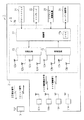
図1及び図2に示すように、車両制御システム1は、車両2の所有者(ユーザ)によって所持される携帯機3と、車両2に配設された車両制御装置4とを備えている。
DESCRIPTION OF EMBODIMENTS Hereinafter, an embodiment embodying the present invention will be described in detail with reference to FIGS.
As shown in FIGS. 1 and 2, the vehicle control system 1 includes a portable device 3 possessed by an owner (user) of the vehicle 2 and a vehicle control device 4 disposed in the vehicle 2.

携帯機3は、無線通信機能を有し、車両制御装置4から送信される送信要求信号としてのID要求信号を受信すると、所定周波数の電波からなる送信信号としてのIDコード信号を自動的に送信する。このIDコード信号は、携帯機3毎に予め設定されたIDコードを含んで構成されている。   When the portable device 3 has a wireless communication function and receives an ID request signal as a transmission request signal transmitted from the vehicle control device 4, the portable device 3 automatically transmits an ID code signal as a transmission signal composed of radio waves of a predetermined frequency. To do. This ID code signal is configured to include an ID code preset for each portable device 3.

車両制御装置4は、車両2の各タイヤ5a〜5dにそれぞれ配設された各センサ装置11a〜11dと、送信手段としての4つの送信アンテナ部12a〜12d及び受信手段としての4つの受信アンテナ部13a〜13dと、制御ユニット14とを備えている。制御ユニット14は、各送信アンテナ部12a〜12dが接続された送信手段としての送信回路15と、各受信アンテナ部13a〜13dが接続された受信手段としての受信回路16と、送信回路15及び受信回路16が接続された制御手段及びドア錠制御手段としての制御部17とを備えている。したがって、各送信アンテナ部12a〜12d及び各受信アンテナ部13a〜13dにより、送受信手段が構成されている。   The vehicle control device 4 includes sensor devices 11a to 11d disposed on the tires 5a to 5d of the vehicle 2, four transmission antenna units 12a to 12d as transmission units, and four reception antenna units as reception units. 13a to 13d and a control unit 14 are provided. The control unit 14 includes a transmission circuit 15 as a transmission unit to which the transmission antenna units 12a to 12d are connected, a reception circuit 16 as a reception unit to which the reception antenna units 13a to 13d are connected, a transmission circuit 15 and a reception unit. A control unit to which a circuit 16 is connected and a control unit 17 as a door lock control unit are provided. Therefore, the transmission antenna units 12a to 12d and the reception antenna units 13a to 13d constitute transmission / reception means.

センサ装置11a〜11dは、それぞれ対応するタイヤ5a〜5dの空気圧(空気圧データ)や温度(温度データ)等のタイヤ情報を検出し、そのタイヤ情報を示すタイヤ情報信号を所定周波数の電波に変換して外部に送信する。なお、本実施形態においてセンサ装置11a〜11dは、対応する送信アンテナ部12a〜12dから送信されるタイヤ情報要求信号を受信した際に、前記タイヤ情報の検出及びタイヤ情報信号の送信を行うようになっている。つまり、各センサ装置11a〜11dは、タイヤ情報要求信号を受信したことをトリガとして作動するようになっている。また、本実施形態においてタイヤ情報信号と前記IDコード信号とは、同じ周波数に設定されている。さらに、本実施形態において各センサ装置11a〜11dは、対応するタイヤのタイヤバルブとそれぞれ一体に形成されている。   The sensor devices 11a to 11d detect tire information such as air pressure (air pressure data) and temperature (temperature data) of the corresponding tires 5a to 5d, respectively, and convert tire information signals indicating the tire information into radio waves of a predetermined frequency. Send it to the outside. In the present embodiment, the sensor devices 11a to 11d detect the tire information and transmit the tire information signal when receiving the tire information request signals transmitted from the corresponding transmitting antenna units 12a to 12d. It has become. In other words, each of the sensor devices 11a to 11d is activated by receiving the tire information request signal as a trigger. In the present embodiment, the tire information signal and the ID code signal are set to the same frequency. Furthermore, in this embodiment, each sensor apparatus 11a-11d is each integrally formed with the tire valve of the corresponding tire.

一方、本実施形態において車両2は4つのドアを有しており、各送信アンテナ部12a〜12d及び各受信アンテナ部13a〜13dは、それらドアにそれぞれ配設されている。具体的には、各送信アンテナ部12a〜12d及び各受信アンテナ部13a〜13dは、各ドアのアウトサイドドアハンドルや、各ドアの内部などに配設されている。このため、各送信アンテナ部12a〜12d及び各受信アンテナ部13a〜13dは、各センサ装置11a〜11dの近傍にそれぞれ対応して配設された状態となっている。なお、各送信アンテナ部12a〜12d及び各受信アンテナ部13a〜13dは、必ずしもドアに配設されている必要はなく、各センサ装置11a〜11dの近傍にそれぞれ対応して配設されているのであれば、どこに配設されてもよい。   On the other hand, in this embodiment, the vehicle 2 has four doors, and each of the transmission antenna units 12a to 12d and each of the reception antenna units 13a to 13d is disposed on each of the doors. Specifically, each of the transmission antenna units 12a to 12d and each of the reception antenna units 13a to 13d is disposed on the outside door handle of each door, the inside of each door, or the like. For this reason, each transmitting antenna part 12a-12d and each receiving antenna part 13a-13d are the states arrange | positioned corresponding to the vicinity of each sensor apparatus 11a-11d, respectively. In addition, since each transmission antenna part 12a-12d and each reception antenna part 13a-13d do not necessarily need to be arrange | positioned at the door, they are each arrange | positioned corresponding to each sensor apparatus 11a-11d vicinity. If it exists, it may be disposed anywhere.

こうした各送信アンテナ部12a〜12dは、制御ユニット14の送信回路15から入力されるタイヤ情報要求信号またはID要求信号を外部に送信する。また、各受信アンテナ部13a〜13dは、対応するセンサ装置11a〜11dから送信されたタイヤ情報信号、または携帯機3から送信されたIDコード信号を受信する。   Each of these transmission antenna units 12a to 12d transmits a tire information request signal or an ID request signal input from the transmission circuit 15 of the control unit 14 to the outside. Moreover, each receiving antenna part 13a-13d receives the tire code | cord | chord information transmitted from corresponding sensor apparatus 11a-11d, or the ID code signal transmitted from the portable device 3.

送信回路15は、制御部17から入力されたタイヤ情報要求信号またはID要求信号を所定周波数の電波に変調し、その変調した電波を、各送信アンテナ部12a〜12dを介して外部に送信する。また、送信回路15は、タイヤ情報要求信号の送信時にあっては、制御部17から入力されるアンテナ制御信号に基づき、各送信アンテナ部12a〜12dのうちの何れか1つのみからタイヤ情報信号を送信させるようになっている。さらに、送信回路15は、制御部17から入力される出力強度制御信号に基づき、各送信アンテナ部12a〜12dから送信される電波の出力強度を変化させることができるように構成されている。なお、本実施形態においてタイヤ情報要求信号とID要求信号とはそれぞれ異なるコードを含んでいる。そして、各センサ装置11a〜11dは、タイヤ情報要求信号の受信時にのみタイヤ情報を送信し、携帯機3は、ID要求信号の受信時にのみIDコード信号を送信するようになっている。   The transmission circuit 15 modulates the tire information request signal or the ID request signal input from the control unit 17 into a radio wave having a predetermined frequency, and transmits the modulated radio wave to the outside via the transmission antenna units 12a to 12d. Further, when transmitting the tire information request signal, the transmission circuit 15 receives the tire information signal from only one of the transmission antenna units 12a to 12d based on the antenna control signal input from the control unit 17. Is supposed to be sent. Further, the transmission circuit 15 is configured to change the output intensity of the radio wave transmitted from each of the transmission antenna units 12a to 12d based on the output intensity control signal input from the control unit 17. In the present embodiment, the tire information request signal and the ID request signal include different codes. And each sensor apparatus 11a-11d transmits tire information only at the time of reception of a tire information request signal, and portable machine 3 transmits an ID code signal only at the time of reception of an ID request signal.

受信回路16は、受信アンテナ部13a〜13dによって受信されたタイヤ情報信号またはIDコード信号をパルス信号に復調し、その復調した信号を制御部17に出力する。
制御部17は、具体的には図示しないCPU、ROM、RAM等からなるCPUユニットであり、図2に示すように不揮発性のメモリ17aを備えている。なお、本実施形態において制御部17は、公知のスマートエントリ機能を有する車両に搭載されているスマートECU(前記背景技術に記載の車両制御部56と同等のハードウェア構成をなすECU)によって構成されている。
The receiving circuit 16 demodulates the tire information signal or ID code signal received by the receiving antenna units 13 a to 13 d into a pulse signal, and outputs the demodulated signal to the control unit 17.
Specifically, the control unit 17 is a CPU unit including a CPU, ROM, RAM, and the like (not shown), and includes a nonvolatile memory 17a as shown in FIG. In the present embodiment, the control unit 17 is configured by a smart ECU (ECU having a hardware configuration equivalent to the vehicle control unit 56 described in the background art) mounted on a vehicle having a known smart entry function. ing.

メモリ17aには、タイヤ5a〜5dの空気圧や温度等の基準データが予め記録されている。この基準データは、タイヤ5a〜5dの空気圧や温度等の正常値を示す値であり、所定の範囲をもって設定されている。また、メモリ17aには、携帯機3に設定されたIDコードと対応するIDコードが記録されている。   In the memory 17a, reference data such as air pressure and temperature of the tires 5a to 5d are recorded in advance. The reference data is a value indicating a normal value such as the air pressure or temperature of the tires 5a to 5d, and is set with a predetermined range. Further, an ID code corresponding to the ID code set in the portable device 3 is recorded in the memory 17a.

図2に示すように、制御部17には、スタートスイッチ21、インジケータ22、電装品としてのドアロック駆動装置23及びエンジン制御部24が電気的に接続されている。
スタートスイッチ21は、車両室内の運転席近傍に設けられたエンジン始動・停止用のスイッチであり、操作された際に操作信号を制御部17に出力する。インジケータ22は、車両2の室内(例えばインストルメントパネル等)に配設されている。このインジケータ22は、制御部17からの作動信号に基づいて表示を行うようになっており、少なくとも前記タイヤ5a〜5dに異常が生じた旨を表示する。ドアロック駆動装置23は、図示しないアクチュエータに接続され、制御部17から駆動信号が入力されると、該アクチュエータを駆動してドア錠を自動的に施解錠する。また、ドアロック駆動装置23は、ドア錠の施解錠状態を示す施解錠状態信号を制御部17に出力する。エンジン制御部24は、図示しないセルモータに接続され、制御部17から始動信号が入力されると、同セルモータを駆動してエンジンを自動的に始動させる。また、エンジン制御部24は、エンジンの駆動状態を示す駆動状態信号を制御部17に出力する。
As shown in FIG. 2, a start switch 21, an indicator 22, a door lock driving device 23 as an electrical component, and an engine control unit 24 are electrically connected to the control unit 17.
The start switch 21 is an engine start / stop switch provided near the driver's seat in the vehicle compartment, and outputs an operation signal to the control unit 17 when operated. The indicator 22 is disposed in the vehicle 2 (for example, an instrument panel). This indicator 22 displays based on the operation signal from the control part 17, and displays that abnormality has occurred in at least the tires 5a to 5d. The door lock drive device 23 is connected to an actuator (not shown). When a drive signal is input from the control unit 17, the door lock drive device 23 drives the actuator to automatically lock and unlock the door. Further, the door lock driving device 23 outputs a lock / unlock state signal indicating the lock / unlock state of the door lock to the control unit 17. The engine control unit 24 is connected to a cell motor (not shown). When a start signal is input from the control unit 17, the engine control unit 24 drives the cell motor to automatically start the engine. Further, the engine control unit 24 outputs a drive state signal indicating the drive state of the engine to the control unit 17.

こうした制御部17は、タイヤ情報要求信号及びID要求信号のうちの何れか一方を、所定のタイミングで送信回路15に出力する。また、制御部17は、送信回路15に出力強度制御信号を出力し、該送信回路15から送信アンテナ部12a〜12dを介して送信される電波の出力強度を制御可能となっている。具体的には、図1に示すように、制御部17は、タイヤ情報要求信号の出力時には第1出力強度制御信号を出力し、該タイヤ情報要求信号の出力領域が少なくとも対応するセンサ装置11a〜11dを含む小領域A1となるように出力強度を制御する。一方、制御部17は、ID要求信号の出力時には第2出力強度制御信号を出力し、該ID要求信号の出力領域が前記小領域A1よりも大きな大領域A2となるように出力強度を制御する。   Such a control unit 17 outputs either one of the tire information request signal and the ID request signal to the transmission circuit 15 at a predetermined timing. Further, the control unit 17 outputs an output intensity control signal to the transmission circuit 15, and can control the output intensity of the radio wave transmitted from the transmission circuit 15 via the transmission antenna units 12a to 12d. Specifically, as shown in FIG. 1, the controller 17 outputs a first output intensity control signal when outputting a tire information request signal, and the sensor devices 11 a to 11 a corresponding to at least the output area of the tire information request signal. The output intensity is controlled to be a small area A1 including 11d. On the other hand, the controller 17 outputs a second output intensity control signal when outputting the ID request signal, and controls the output intensity so that the output area of the ID request signal is a large area A2 larger than the small area A1. .

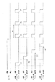
そして、制御部17は、受信回路16からタイヤ情報信号が入力されると、そのタイヤ情報信号に基づいて各タイヤ5a〜5dの監視制御を行う。また、制御部17は、受信回路16からID情報信号が入力されると、そのID情報信号に基づいてドアロック駆動装置23やエンジン制御部24などの電装品の作動制御を行う。そこで、制御部17によって行われるタイヤ情報要求信号及びID要求信号の出力制御と、各タイヤ5a〜5dの監視制御と、電装品の作動制御とを、図3に示すフローチャート及び図4に示すタイムチャートに従って説明する。   When the tire information signal is input from the receiving circuit 16, the control unit 17 performs monitoring control of each tire 5 a to 5 d based on the tire information signal. Further, when the ID information signal is input from the receiving circuit 16, the control unit 17 controls the operation of electrical components such as the door lock driving device 23 and the engine control unit 24 based on the ID information signal. Therefore, the output control of the tire information request signal and the ID request signal, the monitoring control of the tires 5a to 5d, and the operation control of the electrical components performed by the control unit 17, the time chart shown in FIG. 3 and the time shown in FIG. This will be explained according to the chart.

図3に示すように、ステップS1において制御部17は、エンジン制御部24から入力される駆動状態信号に基づき、エンジンが駆動中であるか否かを判断する。そして、制御部17は、エンジンが駆動中であれば、ステップS2〜S4において各タイヤ5a〜5dの監視制御を行う。   As shown in FIG. 3, in step S <b> 1, the control unit 17 determines whether or not the engine is being driven based on the drive state signal input from the engine control unit 24. And if the engine is driving, the control part 17 will perform monitoring control of each tire 5a-5d in step S2-S4.

詳しくは、ステップS2において制御部17は、アンテナ制御信号を送信回路15に出力し、図4にポイントP1〜P4で示すように、各送信アンテナ部12a〜12dから択一的にタイヤ情報要求信号を送信させる。ここで制御部17は、図1に示した小領域A1にタイヤ情報要求信号を送信させる。なお、本実施形態において制御部17は、送信アンテナ部12a→送信アンテナ部12b→送信アンテナ部12c→送信アンテナ部12dの順でタイヤ情報要求信号を送信させるようになっている。   Specifically, in step S2, the control unit 17 outputs an antenna control signal to the transmission circuit 15, and as indicated by points P1 to P4 in FIG. 4, the tire information request signal is alternatively selected from each of the transmission antenna units 12a to 12d. To send. Here, the controller 17 transmits a tire information request signal to the small area A1 shown in FIG. In the present embodiment, the control unit 17 transmits the tire information request signal in the order of the transmission antenna unit 12a → the transmission antenna unit 12b → the transmission antenna unit 12c → the transmission antenna unit 12d.

そして、ステップS3において制御部17は、受信回路16からタイヤ情報信号が入力されたか否かを判断する。すなわち、制御部17は、各送信アンテナ部12a〜12dから送信したタイヤ情報要求信号に応答して送信されたセンサ装置11a〜11dからのタイヤ情報信号が入力されたか否かを判断する。制御部17は、該タイヤ情報信号が入力されると、ステップS4において該タイヤ情報信号に基づいてタイヤ5a〜5dの空気圧状態などをインジケータ22に表示させてここでの処理を一旦終了する。また、制御部17は、ステップS3においてタイヤ情報信号が入力されないと判断すると、再びステップS2の処理へ移行し、対応する送信アンテナ部12a〜12dからタイヤ情報要求信号を送信させる。   In step S <b> 3, the control unit 17 determines whether a tire information signal is input from the receiving circuit 16. That is, the control unit 17 determines whether or not the tire information signals from the sensor devices 11a to 11d transmitted in response to the tire information request signals transmitted from the transmission antenna units 12a to 12d are input. When the tire information signal is input, the control unit 17 displays the air pressure state of the tires 5a to 5d on the indicator 22 on the basis of the tire information signal in step S4, and temporarily ends the processing here. Further, when determining that the tire information signal is not input in step S3, the control unit 17 proceeds to the process of step S2 again, and transmits the tire information request signal from the corresponding transmitting antenna units 12a to 12d.

一方、制御部17は、ステップS1においてエンジンが停止状態であると判断した場合、ステップS5及びステップS6において電装品の作動制御を行う。
詳しくは、制御部17は、図示しない着座センサ等により、車両室内にユーザが存在しないと判断した場合、ステップS5において、図4にポイントP5〜P7で示すように、各送信アンテナ部12a〜12dの全てから同時にID要求信号を送信させる。ここで制御部17は、図1に示した大領域A2にID要求信号を送信させる。なお、同図に示すように、制御部17は、所定の間欠周期ΔtでID要求信号を各送信アンテナ部12a〜12dから送信させるようになっている。
On the other hand, when the control unit 17 determines in step S1 that the engine is in a stopped state, the control unit 17 performs operation control of the electrical components in step S5 and step S6.
Specifically, when the control unit 17 determines that there is no user in the vehicle compartment by using a seating sensor (not shown) or the like, in step S5, as shown by points P5 to P7 in FIG. 4, each transmission antenna unit 12a to 12d. ID request signals are transmitted simultaneously from all of the above. Here, the control unit 17 transmits an ID request signal to the large area A2 illustrated in FIG. As shown in the figure, the control unit 17 transmits the ID request signal from each of the transmission antenna units 12a to 12d at a predetermined intermittent period Δt.

そして、ステップS6において制御部17は、携帯機3から送信されるIDコード信号に基づいて、前記ドアロック駆動装置23の作動制御を行う。詳しくは、まず制御部17は、受信回路16からIDコード信号が入力されたか否かを判断する。すなわち、制御部17は、各送信アンテナ部12a〜12dから送信したID要求信号に応答して送信された携帯機3からのIDコード信号が入力されたか否かを判断する。これにより、該IDコード信号が入力されると、ステップS7において制御部17は、そのIDコード信号に含まれるIDコードとメモリ17aに記録されたIDコードとの比較(IDコード照合)を行う。そして、それらIDコード同士が一致(IDコード照合が成立)した際に、制御部17は、ドアロック駆動装置23に解錠の旨を示す駆動信号(解錠駆動信号)を出力してドア錠を解錠させる。これに対し、該IDコード同士が一致しない場合やIDコード信号が入力されない場合、制御部17は、ドアロック駆動装置23に施錠の旨を示す駆動信号(施錠駆動信号)を出力してドア錠を施錠させる。   In step S <b> 6, the control unit 17 controls the operation of the door lock driving device 23 based on the ID code signal transmitted from the portable device 3. Specifically, first, the control unit 17 determines whether or not an ID code signal is input from the receiving circuit 16. That is, the control unit 17 determines whether or not the ID code signal from the portable device 3 transmitted in response to the ID request signal transmitted from each of the transmission antenna units 12a to 12d is input. Thus, when the ID code signal is input, in step S7, the control unit 17 compares the ID code included in the ID code signal with the ID code recorded in the memory 17a (ID code verification). When these ID codes match (ID code verification is established), the control unit 17 outputs a drive signal (unlock drive signal) indicating unlocking to the door lock drive device 23 to lock the door. To unlock. On the other hand, when the ID codes do not match or when the ID code signal is not input, the control unit 17 outputs a drive signal (locking drive signal) indicating the locking to the door lock driving device 23 to lock the door. Lock.

また、制御部17は、前記着座センサ等により、車両室内にユーザが存在していると判断した場合、ステップS5において、図示しない室内送信アンテナ部から車両室内の所定領域に前記ID要求信号を送信させる。ここで制御部17は、前記間欠周期ΔtでID要求信号を室内送信アンテナから送信させるようになっている。そして、ステップS6において制御部17は、携帯機3から送信されるIDコード信号が入力され、IDコード照合が成立した際に、エンジン始動許可状態となる。制御部17は、このエンジン始動許可状態で前記スタートスイッチ21から操作信号が入力されると、エンジン制御部24に始動信号を出力してエンジンを始動させる。なお、本実施形態においては、シフトポジションセンサ34が「P」レンジまたは「N」レンジに位置し、且つブレーキペダルが踏み込み操作されているときにのみエンジンを始動可能に設定されている。これに対し、該IDコード照合が成立しない場合やIDコード信号が入力されない場合、制御部17は、エンジン始動不可状態となり、たとえスタートスイッチ21から操作信号が入力されてもエンジン制御部24に始動信号を出力しないようになっている。   Further, when the control unit 17 determines that the user is present in the vehicle compartment by the seating sensor or the like, in step S5, the control unit 17 transmits the ID request signal from a not-shown indoor transmission antenna unit to a predetermined region in the vehicle compartment. Let Here, the control unit 17 is configured to transmit the ID request signal from the indoor transmission antenna at the intermittent period Δt. And in step S6, the control part 17 will be in an engine starting permission state, when the ID code signal transmitted from the portable device 3 is input and ID code collation is materialized. When an operation signal is input from the start switch 21 in the engine start permission state, the control unit 17 outputs a start signal to the engine control unit 24 to start the engine. In this embodiment, the engine can be started only when the shift position sensor 34 is in the “P” range or the “N” range and the brake pedal is depressed. On the other hand, when the ID code verification is not established or when the ID code signal is not input, the control unit 17 is in a state where the engine cannot be started, and the engine control unit 24 is started even if an operation signal is input from the start switch 21. The signal is not output.

つまり、本実施形態において、制御部17は、携帯機3との通信の有無に基づいて、ドア錠の施解錠制御及びエンジンの始動許可制御を行うようになっている。
したがって、本実施形態によれば以下のような効果を得ることができる。
That is, in the present embodiment, the control unit 17 performs door lock locking / unlocking control and engine start permission control based on the presence / absence of communication with the portable device 3.
Therefore, according to the present embodiment, the following effects can be obtained.

(1)各センサ装置11a〜11dから送信されるタイヤ情報信号、及び携帯機3から送信されるIDコード信号は、共に受信回路16により受信される。そして、監視制御及び作動制御は、共に制御部17によって行われる。このため、タイヤ情報信号を受信するための受信回路とIDコード信号を受信するための受信回路とを各別に設ける必要がない。また、監視制御を行うための制御部と作動制御を行うための制御部とを各別に設ける必要がない。よって、部品点数の低減を図りつつ、車両制御装置4の多機能化を実現することができる。   (1) The tire information signal transmitted from each of the sensor devices 11 a to 11 d and the ID code signal transmitted from the portable device 3 are both received by the receiving circuit 16. The monitoring control and the operation control are both performed by the control unit 17. For this reason, it is not necessary to provide a receiving circuit for receiving the tire information signal and a receiving circuit for receiving the ID code signal. Further, it is not necessary to provide a control unit for performing monitoring control and a control unit for performing operation control. Therefore, multi-functionalization of the vehicle control device 4 can be realized while reducing the number of parts.

(2)制御部17は、タイヤ情報要求信号及びID要求信号を選択的に出力し、タイヤ情報信号及びIDコード信号がそれら要求信号に応答して入力された際に、監視制御及び作動制御を行う。このため、制御部17は、タイヤ情報信号及びIDコード信号を、必要なときのみに取得することが可能となる。よって、各センサ装置11a〜11dからタイヤ情報信号が無駄に送信されてしまうことを防止することができ、該センサ装置11a〜11dの電力消費量を低減することができる。   (2) The control unit 17 selectively outputs a tire information request signal and an ID request signal, and performs monitoring control and operation control when the tire information signal and the ID code signal are input in response to the request signals. Do. For this reason, the control unit 17 can acquire the tire information signal and the ID code signal only when necessary. Therefore, it is possible to prevent tire information signals from being transmitted from the sensor devices 11a to 11d in vain, and to reduce the power consumption of the sensor devices 11a to 11d.

(3)タイヤ情報要求信号及びID要求信号は、異なる強度の電波で送信される。各センサ装置11a〜11dはタイヤに設けられているため、対応する送信アンテナ部12a〜12dからセンサ装置11a〜11dまでの距離(監視通信距離)が一定である。これに対し、携帯機3はユーザによって所持されるため、各送信アンテナ部12a〜12dから携帯機3までの距離(作動通信距離)は変化する。すなわち、監視通信距離と作動通信距離とは異なる。よって、タイヤ情報要求信号の電波強度と送信要求信号の電波強度とを制御部17によって変化させることにより、それぞれ最適な電波強度で各センサ装置11a〜11d及び携帯機3との通信が可能となる。   (3) The tire information request signal and the ID request signal are transmitted with radio waves having different intensities. Since each of the sensor devices 11a to 11d is provided on the tire, the distance (monitoring communication distance) from the corresponding transmission antenna units 12a to 12d to the sensor devices 11a to 11d is constant. On the other hand, since the portable device 3 is carried by the user, the distance (operating communication distance) from each transmission antenna unit 12a to 12d to the portable device 3 changes. That is, the monitoring communication distance and the working communication distance are different. Therefore, by changing the radio wave intensity of the tire information request signal and the radio wave intensity of the transmission request signal by the control unit 17, it is possible to communicate with each of the sensor devices 11a to 11d and the portable device 3 with the optimal radio wave intensity. .

(4)通常、タイヤの空気圧の監視制御は、車両の走行時、すなわちエンジンが駆動しているときに必要となる。一方、ドアロック駆動装置23やエンジン制御部24などの電装品の作動制御は、エンジンの停止状態において必要となる。このため、エンジンの駆動中にのみタイヤ情報要求信号を送信し、エンジンの停止状態にのみID要求信号を送信することにより、監視制御及び作動制御を好適に行うことができる。   (4) Normally, monitoring control of tire air pressure is required when the vehicle is running, that is, when the engine is being driven. On the other hand, the operation control of the electrical components such as the door lock driving device 23 and the engine control unit 24 is necessary when the engine is stopped. For this reason, monitoring control and operation control can be suitably performed by transmitting a tire information request signal only while the engine is being driven and transmitting an ID request signal only when the engine is stopped.

(5)タイヤ情報要求信号を送信するためのタイヤ用送信手段と、ID要求信号を送信するための携帯機用送信手段とが、各送信アンテナ部12a〜12d及び送信回路15によって共用されている。このため、タイヤ用送信手段と携帯機用送信手段とを個別に設ける必要がなく、部品点数の増加を抑止することができる。   (5) The tire transmission means for transmitting the tire information request signal and the portable device transmission means for transmitting the ID request signal are shared by the transmission antenna units 12a to 12d and the transmission circuit 15. . For this reason, it is not necessary to provide the tire transmission means and the portable device transmission means separately, and the increase in the number of parts can be suppressed.

(6)各送信アンテナ部12a〜12d及び各受信アンテナ部13a〜13dは、車両2の4つのドアにそれぞれ配設されている。このため、車両2の室外における各ドアの周辺にリクエスト信号を確実に送信することができ、携帯機3との通信を確実に行うことができる。しかも、各送信アンテナ部12a〜12d及び各受信アンテナ部13a〜13dは、各センサ装置11a〜11dの近くにそれぞれ対応して配置された状態となる。よって、各送信アンテナ部12a〜12dから送信されるタイヤ情報要求信号が各センサ装置11a〜11dによって受信されやすく、また、各センサ装置11a〜11dから送信されるタイヤ情報信号が各受信アンテナ部13a〜13dによって受信されやすい。すなわち、各送信アンテナ部12a〜12d及び各受信アンテナ部13a〜13dと各センサ装置11a〜11dとの通信を高い信頼性で行うことができる。   (6) The transmitting antenna units 12 a to 12 d and the receiving antenna units 13 a to 13 d are respectively disposed on the four doors of the vehicle 2. For this reason, a request signal can be reliably transmitted to the periphery of each door outside the vehicle 2, and communication with the portable device 3 can be reliably performed. In addition, each of the transmission antenna units 12a to 12d and each of the reception antenna units 13a to 13d is in a state of being arranged corresponding to each other in the vicinity of each of the sensor devices 11a to 11d. Therefore, tire information request signals transmitted from the transmission antenna units 12a to 12d are easily received by the sensor devices 11a to 11d, and tire information signals transmitted from the sensor devices 11a to 11d are received by the reception antenna units 13a. It is easy to be received by ~ 13d. That is, communication with each transmission antenna part 12a-12d, each reception antenna part 13a-13d, and each sensor apparatus 11a-11d can be performed with high reliability.

なお、本発明の実施形態は以下のように変更してもよい。
・ 前記実施形態において制御部17は、エンジンが駆動していることを条件として各タイヤ5a〜5dの監視制御を行い、エンジンが停止していることを条件として電装品の作動制御を行うようになっている。しかし、制御部17は、必ずしもエンジンの駆動中にのみ該監視制御を行うようになっている必要はない。つまり、制御部17が監視制御を行うタイミングは、エンジンが駆動したことに限定されない。例えば、制御部17は、車両2の室内で携帯機3との通信が成立したこと、すなわちエンジン始動許可状態となったことを条件として、該監視制御を行うようになっていてもよい。
In addition, you may change embodiment of this invention as follows.
In the embodiment, the control unit 17 performs monitoring control of the tires 5a to 5d on the condition that the engine is driven, and performs operation control of the electrical components on the condition that the engine is stopped. It has become. However, the control unit 17 does not necessarily need to perform the monitoring control only while the engine is being driven. That is, the timing at which the control unit 17 performs the monitoring control is not limited to the driving of the engine. For example, the control unit 17 may perform the monitoring control on the condition that the communication with the portable device 3 is established in the room of the vehicle 2, that is, the engine start permission state.

・ 前記実施形態において車両制御装置4は、タイヤ情報要求信号を送信するための送信手段と、ID要求信号を送信するための送信手段とを、各送信アンテナ部12a〜12d及び送信回路15によって共用している。しかし、車両制御装置4は、タイヤ情報要求信号のみを送信する送信アンテナ部及び送信回路と、ID要求信号のみを送信する送信アンテナ部及び送信回路とを、個別に備えていてもよい。   -In the said embodiment, the vehicle control apparatus 4 shares the transmission means for transmitting a tire information request signal, and the transmission means for transmitting ID request signal by each transmission antenna part 12a-12d and the transmission circuit 15. doing. However, the vehicle control device 4 may individually include a transmission antenna unit and a transmission circuit that transmit only the tire information request signal, and a transmission antenna unit and a transmission circuit that transmit only the ID request signal.

・ 前記受信回路16は受信感度を変更に構成されていてもよい。そして、制御部17は、タイヤ情報信号の受信待機時とIDコード信号の受信待機時とで、受信回路16の受信感度を変更する感度変更制御を行うようになっていてもよい。例えば、制御部17は、受信回路16の受信感度、すなわち各受信アンテナ部13a〜13dの受信感度を、タイヤ情報要求信号を出力する際には低くし、ID要求信号を出力する際には高くするように感度変更制御を行うようになっていてもよい。このようにすれば、特にタイヤ5a〜5dの監視制御中にあっては、各受信アンテナ部13a〜13dがノイズを受信しにくくなり、好適な監視制御を行うことができる。   The receiving circuit 16 may be configured to change the receiving sensitivity. And the control part 17 may perform the sensitivity change control which changes the reception sensitivity of the receiving circuit 16 at the time of the reception standby of a tire information signal, and the reception standby of an ID code signal. For example, the control unit 17 lowers the reception sensitivity of the reception circuit 16, that is, the reception sensitivity of each of the reception antenna units 13a to 13d when outputting a tire information request signal, and increases when receiving an ID request signal. Thus, sensitivity change control may be performed. In this way, particularly during the monitoring control of the tires 5a to 5d, the receiving antenna units 13a to 13d are less likely to receive noise, and suitable monitoring control can be performed.

・ 前記実施形態において送信回路15は各送信アンテナ部12a〜12dから送信する電波の強度を変更可能に構成されているが、必ずしも変更可能である必要はない。例えば、タイヤ情報要求信号は、前記大領域A2に送信されるようになっていてもよい。   In the above-described embodiment, the transmission circuit 15 is configured to be able to change the intensity of the radio wave transmitted from each of the transmission antenna units 12a to 12d, but it is not necessarily changeable. For example, the tire information request signal may be transmitted to the large area A2.

・ 前記実施形態において制御部17は、エンジンの駆動状態にあってはタイヤ情報要求信号のみを出力して各タイヤ5a〜5dの監視制御のみを行い、エンジンの停止状態にあってはID要求信号のみを出力して電装品の作動制御のみを行うようになっている。しかし、制御部17は、エンジンの駆動状態においてもID要求信号を出力して作動制御を行ってもよく、またエンジンの停止状態においてもタイヤ情報要求信号を出力して監視制御を行うようになっていてもよい。但し、エンジンの駆動状態にあってはタイヤ情報要求信号の出力比率が高く、エンジンの停止状態にあってはID要求信号の出力比率が高く設定されているのが好ましい。   In the embodiment, the control unit 17 outputs only the tire information request signal when the engine is in a driving state and performs only the monitoring control of the tires 5a to 5d, and the ID request signal when the engine is in a stopped state. Only the operation control of the electrical components is performed by outputting only. However, the control unit 17 may perform operation control by outputting an ID request signal even when the engine is in a driving state, and perform monitoring control by outputting a tire information request signal even when the engine is stopped. It may be. However, it is preferable that the output ratio of the tire information request signal is high when the engine is in a driving state, and the output ratio of the ID request signal is high when the engine is in a stopped state.

・ 前記実施形態において車両制御装置4は、各センサ装置11a〜11dと対応して設けられた送信アンテナ部12a〜12dと、送信回路15とを備えている。しかし、これら送信アンテナ部12a〜12d及び送信回路15を省略してもよい。但しこの場合、各センサ装置11a〜11dは、タイヤ情報信号を自動的に送信するようになっている必要がある。例えば、各センサ装置11a〜11dは、所定の間欠周期でタイヤ情報信号を自動的に送信するようになっている必要がある。   -In the said embodiment, the vehicle control apparatus 4 is provided with the transmission antenna parts 12a-12d provided corresponding to each sensor apparatus 11a-11d, and the transmission circuit 15. FIG. However, the transmission antenna units 12a to 12d and the transmission circuit 15 may be omitted. However, in this case, each of the sensor devices 11a to 11d needs to automatically transmit a tire information signal. For example, each of the sensor devices 11a to 11d needs to automatically transmit a tire information signal at a predetermined intermittent period.

・ 前記実施形態においてタイヤ情報信号及びIDコード信号は、同一の周波数に設定されている。しかし、タイヤ情報信号及びIDコード信号は、異なる周波数に設定されてもよい。それに伴い、受信回路16は、受信周波数を変更可能に構成されてもよい。加えて、制御部17は、タイヤ情報信号の受信待機状態と送信信号の受信待機状態とで、受信回路16の受信周波数を変更する周波数変更制御を行うようになっていてもよい。このようにすれば、タイヤ情報信号と送信信号との混信を確実に防止することができ、監視制御及び作動制御を好適に行うことができる。   In the embodiment, the tire information signal and the ID code signal are set to the same frequency. However, the tire information signal and the ID code signal may be set to different frequencies. Accordingly, the reception circuit 16 may be configured to change the reception frequency. In addition, the control unit 17 may perform frequency change control for changing the reception frequency of the reception circuit 16 between the tire information signal reception standby state and the transmission signal reception standby state. If it does in this way, interference with a tire information signal and a transmission signal can be prevented certainly, and monitoring control and operation control can be performed suitably.

次に、特許請求の範囲に記載された技術的思想のほかに、前述した実施形態によって把握される技術的思想を以下に列挙する。
(1) 請求項2に記載の車両制御装置において、前記受信手段は受信感度を変更可能に構成され、前記制御手段は、前記受信手段による前記タイヤ情報信号の受信待機状態と前記送信信号の受信待機状態とで、該受信手段の受信感度を変化させる感度変更制御を行うこと。
Next, in addition to the technical ideas described in the claims, the technical ideas grasped by the embodiment described above are listed below.
(1) The vehicle control device according to claim 2, wherein the reception unit is configured to be able to change a reception sensitivity, and the control unit receives the tire information signal by the reception unit and receives the transmission signal. Sensitivity change control for changing the receiving sensitivity of the receiving means in the standby state.

(2) 請求項3に記載の車両制御装置において、前記送信手段は、送信する電波の強度を変更可能に構成され、前記制御手段は、前記タイヤ情報要求信号の出力時と前記送信要求信号の出力時とで、前記送信手段から送信される電波の強度を制御すること。この技術的思想(2)に記載の発明によれば、タイヤ情報要求信号及び送信要求信号は、異なる強度の電波で送信される。各センサ装置はタイヤに設けられているため送信手段からセンサ装置までの距離(監視通信距離)が一定であるのに対し、携帯機はユーザによって所持されるため送信手段から携帯機までの距離(作動通信距離)は変化する。すなわち、監視通信距離と作動通信距離とは異なる。よって、タイヤ情報要求信号の電波強度と送信要求信号の電波強度とを制御手段によって変化させることにより、それぞれ最適な電波強度で各センサ装置及び携帯機との通信が可能となる。   (2) In the vehicle control device according to claim 3, the transmission means is configured to be able to change the intensity of a radio wave to be transmitted, and the control means is configured to output the tire information request signal and the transmission request signal. Controlling the intensity of the radio wave transmitted from the transmission means at the time of output. According to the invention described in this technical idea (2), the tire information request signal and the transmission request signal are transmitted with radio waves having different intensities. Since each sensor device is provided on the tire, the distance from the transmission means to the sensor device (monitoring communication distance) is constant, whereas the portable device is carried by the user, so the distance from the transmission means to the portable device ( The working communication distance will vary. That is, the monitoring communication distance and the working communication distance are different. Therefore, by changing the radio wave intensity of the tire information request signal and the radio wave intensity of the transmission request signal by the control means, it is possible to communicate with each sensor device and portable device with the optimum radio wave intensity.

(3) 請求項3または技術的思想(2)に記載の車両制御装置において、前記制御手段は、少なくともエンジンの駆動状態を示すエンジン駆動情報を含む車両情報に基づいて、前記タイヤ情報要求信号及び前記送信要求信号の出力比率を変化させること。この技術的思想(3)に記載の発明によれば、通常、タイヤの空気圧の監視制御は、車両の走行時、すなわちエンジンが駆動しているときに必要となる。一方、例えば送信信号に基づいてドア錠の施解錠やエンジンの始動許可を制御するセキュリティ制御システムとして車両制御装置を具体化した場合などには、電装品の作動制御は、エンジンの停止状態において必要となる。このため、エンジンの駆動状態と停止状態とでタイヤ情報要求信号及び送信要求信号の出力比率を変化させることにより、監視制御及び作動制御を好適に行うことができる。   (3) In the vehicle control device according to claim 3 or the technical idea (2), the control means includes at least the tire information request signal and the tire information request signal based on vehicle information including engine drive information indicating an engine drive state. Changing an output ratio of the transmission request signal; According to the invention described in the technical idea (3), usually, the tire air pressure monitoring control is required when the vehicle is running, that is, when the engine is being driven. On the other hand, for example, when the vehicle control device is embodied as a security control system that controls locking / unlocking of door locks and engine start permission based on a transmission signal, the operation control of electrical components is necessary when the engine is stopped. It becomes. For this reason, monitoring control and operation control can be suitably performed by changing the output ratio of the tire information request signal and the transmission request signal between the driving state and the stopped state of the engine.

(4) 技術的思想(2)に記載の車両制御装置において、前記制御手段は、前記タイヤ情報要求信号の送信時には、前記送信要求信号の送信時よりも電波の強度が低くなるように前記送信手段を制御すること。   (4) In the vehicle control device described in the technical idea (2), the control unit transmits the tire information request signal so that the radio wave intensity is lower than that of the transmission request signal. Control means.

(5) 技術的思想(3)に記載の車両制御装置において、前記制御手段は、エンジンの駆動状態にあっては前記タイヤ情報要求信号を高い比率で出力し、エンジンの停止状態にあっては前記送信要求信号を高い比率で出力すること。   (5) In the vehicle control device described in the technical concept (3), the control means outputs the tire information request signal at a high rate when the engine is in a driving state, and when the engine is in a stopped state. Outputting the transmission request signal at a high rate.

(6) 請求項3、技術的思想(2)〜(5)のいずれか1項に記載の車両制御装置において、前記タイヤ情報信号の送信周波数と、前記送信信号の送信周波数とは、同一の周波数に設定されていること。   (6) In the vehicle control device according to any one of claim 3 and technical ideas (2) to (5), the transmission frequency of the tire information signal and the transmission frequency of the transmission signal are the same. Must be set to frequency.

(7) 請求項3、技術的思想(2)〜(6)のいずれか1項に記載の車両制御装置において、前記送信手段は、前記各センサ装置の近傍にそれぞれ配設された送信アンテナ部と、前記制御手段から入力される入力信号を電波に変調して各送信アンテナ部から送信する一つの送信回路とを備えていること。   (7) The vehicle control device according to any one of claims 3 and technical ideas (2) to (6), wherein the transmitting means is a transmitting antenna unit disposed in the vicinity of each of the sensor devices. And a transmission circuit that modulates an input signal input from the control means into a radio wave and transmits the radio signal from each transmission antenna unit.

(8) 請求項1〜3、技術的思想(1)〜(7)のいずれか1項に記載の車両制御装置において、前記受信手段は、前記各センサ装置の近傍にそれぞれ配設された受信アンテナ部と、それら受信アンテナ部によって受信された電波を復調して前記制御手段に出力する一つの受信回路とを備えていること。   (8) In the vehicle control device according to any one of claims 1 to 3 and technical ideas (1) to (7), the receiving means is a receiver disposed in the vicinity of each of the sensor devices. An antenna unit; and a single receiving circuit that demodulates radio waves received by the receiving antenna unit and outputs the demodulated signal to the control means.

(9) 車両の複数のタイヤにそれぞれ個別に設けられ、所定のタイヤ情報要求信号を受信したことを条件として、対応するタイヤの少なくとも空気圧データを含むタイヤ情報信号を自動的に送信することを特徴とするセンサ装置。   (9) A tire information signal that is provided individually for each of a plurality of tires of a vehicle and automatically transmits a tire information signal including at least air pressure data of the corresponding tire on condition that a predetermined tire information request signal is received. Sensor device.

本発明の一実施形態の車両制御装置を搭載した車両の概略的に示す平面図。The top view showing roughly the vehicles carrying the vehicle control device of one embodiment of the present invention. 同実施形態の車両制御システムの概略構成を示すブロック図。The block diagram which shows schematic structure of the vehicle control system of the embodiment. 同実施形態の制御手段の処理を示すフローチャート。The flowchart which shows the process of the control means of the embodiment. 同実施形態の制御態様の一例を示すタイムチャート。The time chart which shows an example of the control aspect of the embodiment. 従来の車両用セキュリティ制御装置の概略構成を示すブロック図。The block diagram which shows schematic structure of the conventional vehicle security control apparatus. 従来のタイヤ空気圧監視装置の概略構成を示すブロック図。The block diagram which shows schematic structure of the conventional tire pressure monitoring apparatus.

符号の説明Explanation of symbols

1…車両制御システム、2…車両、3…携帯機、4…車両制御装置、5a〜5d…タイヤ、11a〜11d…センサ装置、12a〜12d…送信アンテナ部、13a〜13d…受信アンテナ部、15…送信回路、16…受信回路、17…制御手段としての制御部、23…電装品としてのドアロック駆動装置、24…電装品としてのエンジン制御部。   DESCRIPTION OF SYMBOLS 1 ... Vehicle control system, 2 ... Vehicle, 3 ... Portable machine, 4 ... Vehicle control apparatus, 5a-5d ... Tire, 11a-11d ... Sensor apparatus, 12a-12d ... Transmission antenna part, 13a-13d ... Reception antenna part, DESCRIPTION OF SYMBOLS 15 ... Transmission circuit, 16 ... Reception circuit, 17 ... Control part as control means, 23 ... Door lock drive device as electrical equipment, 24 ... Engine control part as electrical equipment.

Claims (5)

車両の複数のタイヤにそれぞれ個別に設けられ、対応するタイヤの少なくとも空気圧データを含むタイヤ情報信号を電波で送信する複数のセンサ装置と、
前記タイヤ情報信号を受信するとともに、通信機能を有する携帯機から電波で送信される送信信号を受信する受信手段と、
前記受信手段によって受信された前記タイヤ情報信号に基づいて前記各センサ装置と対応するタイヤの少なくとも空気圧を監視する監視制御を行うとともに、前記携帯機からの送信信号に基づいて車両の所定の電装品の作動制御を行う制御手段と、
を備えることを特徴とする車両制御装置。
A plurality of sensor devices that are individually provided to a plurality of tires of a vehicle, and transmit a tire information signal including at least air pressure data of the corresponding tires by radio waves;
Receiving means for receiving the tire information signal and receiving a transmission signal transmitted by radio waves from a portable device having a communication function;
Based on the tire information signal received by the receiving means, monitoring control is performed to monitor at least the air pressure of the tire corresponding to each sensor device, and a predetermined electrical component of the vehicle is based on a transmission signal from the portable device Control means for controlling the operation of
A vehicle control device comprising:
前記タイヤ情報信号は、前記送信信号と異なる周波数に設定され、
前記受信手段は、受信周波数を変更可能に構成され、
前記制御手段は、前記受信手段による前記タイヤ情報信号の受信待機状態にあっては該タイヤ情報信号の周波数、該受信手段による前記送信信号の受信待機状態にあっては該送信信号の周波数となるように、該受信手段の受信周波数を制御することを特徴とする請求項1に記載の車両制御装置。
The tire information signal is set to a frequency different from the transmission signal,
The receiving means is configured to be able to change the reception frequency,
The control means has a frequency of the tire information signal when the reception means is in a reception standby state of the tire information signal, and a frequency of the transmission signal when the reception means is in a reception standby state of the transmission signal. Thus, the vehicle control apparatus according to claim 1, wherein the receiving frequency of the receiving means is controlled.
前記制御手段から入力される入力信号を電波に変調して送信する送信手段を備え、
前記制御手段は、前記入力信号として、前記センサ装置に対して前記タイヤ情報信号の送信を要求するタイヤ情報要求信号と、前記携帯機に対して前記送信信号の送信を要求する送信要求信号とを選択的に出力する制御を行うとともに、該タイヤ情報要求信号に応答して送信された前記タイヤ情報信号が前記受信手段から入力された際に前記監視制御を行い、該送信要求信号に応答して送信された前記送信信号が前記受信手段から入力された際に前記作動制御を行うことを特徴とする請求項1または請求項2に記載の車両制御装置。
A transmission means for modulating the input signal input from the control means into a radio wave and transmitting it;
The control means, as the input signal, a tire information request signal that requests the sensor device to transmit the tire information signal, and a transmission request signal that requests the portable device to transmit the transmission signal. In addition to performing control to selectively output, the monitoring control is performed when the tire information signal transmitted in response to the tire information request signal is input from the receiving means, and in response to the transmission request signal The vehicle control device according to claim 1, wherein the operation control is performed when the transmitted transmission signal is input from the receiving unit.
通信機能を有する携帯機に対して送信信号の送信を要求する旨を示すリクエスト信号を車両室外の所定領域に電波で送信するとともに、該携帯機から電波で送信される前記送信信号を受信する送受信手段と、前記リクエスト信号に応答して送信された前記送信信号が前記送受信手段によって受信されたか否かに基づいてドアロック駆動装置を駆動制御してドア錠を施解錠するドア錠制御手段とを備えた車両用施解錠制御装置において、
前記送受信手段は、車両の複数のタイヤにそれぞれ個別に設けられた複数のセンサ装置から電波で送信される、それぞれ対応するタイヤの少なくとも空気圧データを含むタイヤ情報信号を、受信可能であることを特徴とする車両制御装置。
Transmission / reception of a request signal indicating that a portable device having a communication function is requested to transmit a transmission signal by radio wave to a predetermined area outside the vehicle compartment and receiving the transmission signal transmitted from the portable device by radio wave And a door lock control means for driving and controlling the door lock driving device to lock and unlock the door based on whether the transmission signal transmitted in response to the request signal is received by the transmission / reception means. In the vehicle locking / unlocking control device provided,
The transmission / reception means is capable of receiving tire information signals including at least air pressure data of corresponding tires, which are transmitted by radio waves from a plurality of sensor devices individually provided on a plurality of tires of a vehicle. A vehicle control device.
前記ドア錠制御手段は、前記受信手段によって受信された前記タイヤ情報信号に基づいて前記各センサ装置と対応するタイヤの少なくとも空気圧を監視する監視制御を行うことを特徴とする請求項4に記載の車両制御装置。   The said door lock control means performs monitoring control which monitors at least the air pressure of the tire corresponding to each said sensor apparatus based on the said tire information signal received by the said receiving means. Vehicle control device.
JP2003423650A 2003-12-19 2003-12-19 Vehicle controller Pending JP2005178635A (en)

Priority Applications (1)

Application Number Priority Date Filing Date Title
JP2003423650A JP2005178635A (en) 2003-12-19 2003-12-19 Vehicle controller

Applications Claiming Priority (1)

Application Number Priority Date Filing Date Title
JP2003423650A JP2005178635A (en) 2003-12-19 2003-12-19 Vehicle controller

Publications (1)

Publication Number Publication Date
JP2005178635A true JP2005178635A (en) 2005-07-07

Family

ID=34784113

Family Applications (1)

Application Number Title Priority Date Filing Date
JP2003423650A Pending JP2005178635A (en) 2003-12-19 2003-12-19 Vehicle controller

Country Status (1)

Country Link
JP (1) JP2005178635A (en)

Cited By (9)

* Cited by examiner, † Cited by third party
Publication number Priority date Publication date Assignee Title
JP2007261454A (en) * 2006-03-29 2007-10-11 Aisin Seiki Co Ltd Tire pneumatic pressure monitoring system
JP2008087704A (en) * 2006-10-04 2008-04-17 Bridgestone Corp Tire information management system
JP2011126461A (en) * 2009-12-18 2011-06-30 Pacific Ind Co Ltd Tire condition monitoring device equipped with keyless entry function
JP2012101709A (en) * 2010-11-11 2012-05-31 Tokai Rika Co Ltd On-vehicle communication instrument
JP2012101710A (en) * 2010-11-11 2012-05-31 Tokai Rika Co Ltd On-vehicle communication instrument
JP2012112196A (en) * 2010-11-26 2012-06-14 Denso Corp Electronic key system
JP2012126192A (en) * 2010-12-14 2012-07-05 Denso Corp Id registration system for tire air pressure sensor
CN103253232A (en) * 2006-08-01 2013-08-21 雅马哈发动机株式会社 Vehicle control apparatus and vehicle having the same
JP2016141270A (en) * 2015-02-02 2016-08-08 アルプス電気株式会社 Tire pneumatic pressure detection system

Cited By (12)

* Cited by examiner, † Cited by third party
Publication number Priority date Publication date Assignee Title
JP2007261454A (en) * 2006-03-29 2007-10-11 Aisin Seiki Co Ltd Tire pneumatic pressure monitoring system
CN103253232A (en) * 2006-08-01 2013-08-21 雅马哈发动机株式会社 Vehicle control apparatus and vehicle having the same
CN103253232B (en) * 2006-08-01 2015-10-21 雅马哈发动机株式会社 Controller of vehicle and there is the vehicle of this controller of vehicle
JP2008087704A (en) * 2006-10-04 2008-04-17 Bridgestone Corp Tire information management system
WO2008044540A1 (en) * 2006-10-04 2008-04-17 Bridgestone Corporation Tire information management system
US8115614B2 (en) 2006-10-04 2012-02-14 Bridgestone Corporation Tire information management system
JP2011126461A (en) * 2009-12-18 2011-06-30 Pacific Ind Co Ltd Tire condition monitoring device equipped with keyless entry function
JP2012101709A (en) * 2010-11-11 2012-05-31 Tokai Rika Co Ltd On-vehicle communication instrument
JP2012101710A (en) * 2010-11-11 2012-05-31 Tokai Rika Co Ltd On-vehicle communication instrument
JP2012112196A (en) * 2010-11-26 2012-06-14 Denso Corp Electronic key system
JP2012126192A (en) * 2010-12-14 2012-07-05 Denso Corp Id registration system for tire air pressure sensor
JP2016141270A (en) * 2015-02-02 2016-08-08 アルプス電気株式会社 Tire pneumatic pressure detection system

Similar Documents

Publication Publication Date Title
US10737659B2 (en) Protocols for remote vehicle access systems
US7656270B2 (en) Keyless entry device with passive and active entry modes
JP5186475B2 (en) Tire condition monitoring device with keyless entry function
JP4140731B2 (en) Vehicle communication device
US6647773B2 (en) System and method for integrated tire pressure monitoring and passive entry
US20080100429A1 (en) Tire pressure monitoring (tpm) and remote keyless entry (rke) system for a vehicle
JP2004189072A (en) Passive keyless entry device to perform tire pneumatic pressure monitoring through bidirectional communications
JP4690218B2 (en) Portable device having wireless communication function
JP2004009923A (en) Vehicle-mounted equipment remote control
JP2007191891A (en) Remote control system for vehicle-mounted equipment
JP2018107653A (en) Authentication system for vehicle
JP2004027490A (en) Vehicle remote control system, and portable machine for vehicle remote control system
JP2005178635A (en) Vehicle controller
JP4285211B2 (en) Information processing apparatus and wheel information processing apparatus for vehicle
JP2010064722A (en) Vehicular operation monitoring system
JP4585961B2 (en) Wireless communication control system
US9114670B2 (en) Multifunction receiver
EP3470275A1 (en) Wireless communication system
JP5278908B2 (en) Remote starter for vehicle and remote start system
JP2006152763A (en) On-vehicle communication control system
JP2008278431A (en) Vehicle control system
JP2005226254A (en) Portable machine
JP2008169663A (en) Portable machine and vehicular remote control system using the same
JP4384946B2 (en) Passive keyless entry device
JP2008132911A (en) On-vehicle electronic control device