JP2005177480A - Movable canopy for infant care apparatus - Google Patents
Movable canopy for infant care apparatus Download PDFInfo
- Publication number
- JP2005177480A JP2005177480A JP2004362722A JP2004362722A JP2005177480A JP 2005177480 A JP2005177480 A JP 2005177480A JP 2004362722 A JP2004362722 A JP 2004362722A JP 2004362722 A JP2004362722 A JP 2004362722A JP 2005177480 A JP2005177480 A JP 2005177480A
- Authority
- JP
- Japan
- Prior art keywords
- infant
- canopy
- platform
- care apparatus
- obstacle
- Prior art date
- Legal status (The legal status is an assumption and is not a legal conclusion. Google has not performed a legal analysis and makes no representation as to the accuracy of the status listed.)
- Pending
Links
Images


Classifications
-
- A—HUMAN NECESSITIES
- A61—MEDICAL OR VETERINARY SCIENCE; HYGIENE
- A61G—TRANSPORT, PERSONAL CONVEYANCES, OR ACCOMMODATION SPECIALLY ADAPTED FOR PATIENTS OR DISABLED PERSONS; OPERATING TABLES OR CHAIRS; CHAIRS FOR DENTISTRY; FUNERAL DEVICES
- A61G11/00—Baby-incubators; Couveuses
-
- A—HUMAN NECESSITIES
- A61—MEDICAL OR VETERINARY SCIENCE; HYGIENE
- A61G—TRANSPORT, PERSONAL CONVEYANCES, OR ACCOMMODATION SPECIALLY ADAPTED FOR PATIENTS OR DISABLED PERSONS; OPERATING TABLES OR CHAIRS; CHAIRS FOR DENTISTRY; FUNERAL DEVICES
- A61G11/00—Baby-incubators; Couveuses
- A61G11/001—Baby-incubators; Couveuses with height-adjustable elements
- A61G11/002—Baby-incubators; Couveuses with height-adjustable elements height-adjustable patient support
-
- A—HUMAN NECESSITIES
- A61—MEDICAL OR VETERINARY SCIENCE; HYGIENE
- A61G—TRANSPORT, PERSONAL CONVEYANCES, OR ACCOMMODATION SPECIALLY ADAPTED FOR PATIENTS OR DISABLED PERSONS; OPERATING TABLES OR CHAIRS; CHAIRS FOR DENTISTRY; FUNERAL DEVICES
- A61G11/00—Baby-incubators; Couveuses
- A61G11/005—Baby-incubators; Couveuses with movable walls, e.g. for accessing the inside, removable walls
-
- A—HUMAN NECESSITIES
- A61—MEDICAL OR VETERINARY SCIENCE; HYGIENE
- A61G—TRANSPORT, PERSONAL CONVEYANCES, OR ACCOMMODATION SPECIALLY ADAPTED FOR PATIENTS OR DISABLED PERSONS; OPERATING TABLES OR CHAIRS; CHAIRS FOR DENTISTRY; FUNERAL DEVICES
- A61G11/00—Baby-incubators; Couveuses
- A61G11/009—Baby-incubators; Couveuses with hand insertion windows, e.g. in the walls
Abstract
Description
本発明は、乳児ケア装置に関し、より具体的には、オーバーヘッド式放射加熱器と、乳児の上方に配置されたピボット運動可能なキャノピとを有する乳児加温装置に関する。 The present invention relates to an infant care apparatus, and more particularly to an infant warming apparatus having an overhead radiant heater and a pivotable canopy disposed above the infant.
新生児のケアにおいて、乳児に熱を与える様々な種類の装置があり、こうした装置は、乳児保育器、乳児加温器、及びこの2つの組み合わせを含むことができる。こうした装置においては、通常、世話を受けるように上に乳児が置かれる乳児用プラットフォームが設けられ、この乳児用プラットフォームは、乳児を横たえるように配置されたほぼ平坦な面である。乳児加温器と共に、乳児を暖めるために、赤外線スペクトルのエネルギーを活性化して、乳児用プラットフォーム上に載せられている乳児の方向に向けることができるオーバーヘッド式放射加熱器も存在する。
特定の乳児用装置においては、乳児を囲む乳児用コンパートメントも設けられ、この乳児用コンパートメントは、これにより乳児が制御された環境の中にいることができる囲まれた領域を形成し、そこで、乳児の健康のために有利な環境を作り出すように、熱及び場合によっては湿度が制御される。この乳児用コンパートメントは、乳児の上方に配置されたキャノピの存在によって形成され、これにより乳児用プラットフォーム上にいる乳児が囲まれる。
There are various types of devices that provide heat to infants in neonatal care, and such devices can include infant incubators, infant warmers, and combinations of the two. Such devices are usually provided with an infant platform on which an infant is placed to be cared for, and the infant platform is a substantially flat surface arranged to lay the infant. Along with the infant warmer, there is also an overhead radiant heater that can activate the energy in the infrared spectrum to direct the infant on the infant platform to warm the infant.
In certain infant devices, an infant compartment surrounding the infant is also provided, which forms an enclosed area where the infant can be in a controlled environment, where the infant is Heat and, in some cases, humidity are controlled to create a favorable environment for health. This infant compartment is formed by the presence of a canopy located above the infant, which encloses the infant on the infant platform.
この特許の従来技術として、乳児加温器が、Falk他の米国特許第5,474,517号に示され説明されており、乳児保育器が、Mackin他の米国特許第4,936,824号に示され説明されており、乳児加温器と乳児保育器両方の機能を組み合わせる組み合わせ装置が、Jones他の米国特許第6,224,539号に示され説明されている。
乳児の世話をするための更に別の装置として、「Infant Care Apparatus with Fixed Overhead Heater」という名称の、Falk他の係属中の米国特許出願第10/672,948号に示され説明されるような、移動可能なキャノピと共に、乳児用プラットフォームの上方に取り付けられた固定加温器があり、この特許の開示の全体を引用によりここに組み入れる。しかしながら、後者の装置においては、移動キャノピがあり、放射加温器自体は、定位置に保持されている。
As prior art to this patent, an infant warmer is shown and described in US Pat. No. 5,474,517 to Falk et al. And an infant incubator is described in US Pat. No. 4,936,824 to Mackin et al. A combined device that combines the functions of both an infant warmer and an infant incubator is shown and described in US Pat. No. 6,224,539 to Jones et al.
As yet another apparatus for caring for infants, as shown and described in Falk et al., Pending US patent application Ser. No. 10 / 672,948, entitled “Infant Care Apparatus with Fixed Overhead Heater”. There is a fixed warmer mounted above the infant platform, along with a movable canopy, the entire disclosure of which is incorporated herein by reference. However, the latter device has a moving canopy and the radiant warmer itself is held in place.
しかしながら、乳児用コンパートメントを形成するために乳児を覆うキャノピを用いる1つの問題は、乳児にアクセスするために、或いは乳児をその乳児用コンパートメントに入れたり、該乳児用コンパートメントから出したりするために、明らかに該キャノピを開けなければならない場合がある点である。したがって、キャノピを、乳児用コンパートメントが乳児を囲む閉位置と、乳児に介入又は処置を行うために該乳児にアクセス可能な開位置との間で移動できる、幾つかの手段がなければならない。
したがって、開位置と閉位置との間でキャノピを移動することを可能にするために設けることができる1つの便利な方法は、好ましくはほぼ長方形の底面積の構成の短い方の端部の1つにおいて、通常は、装置の北端部としてここに定義される端部すなわち通常該装置の機能を実行する際に用いられる制御装置及びモニタが配置され、乳児加温装置の使用中に従来より乳児の頭部が位置する該装置の端部である端部において、キャノピをピボット運動することによるものである。
However, one problem with using an infant canopy to form an infant compartment is to access the infant or to put the infant in or out of the infant compartment. Obviously, the canopy may need to be opened. Accordingly, there must be some means by which the canopy can be moved between a closed position in which the infant compartment surrounds the infant and an open position accessible to the infant for intervention or treatment of the infant.
Thus, one convenient method that can be provided to allow the canopy to move between the open and closed positions is preferably one of the shorter ends of the substantially rectangular base area configuration. On the other hand, usually the end defined here as the north end of the device, i.e. the control device and the monitor normally used in carrying out the function of the device, is arranged, and the infant is conventionally used during the use of the infant warming device. By pivoting the canopy at the end, which is the end of the device where the head of the device is located.
しかしながら、開位置と閉位置との間を、キャノピをその一端においてピボット運動する際に生じる問題は、乳児用プラットフォームの上方に頭上障害物が配置されることが多いために、該キャノピが上方にピボット運動された時に、該キャノピの長い寸法により、該キャノピが該障害物にぶつかるか又は当たり、北回りの該キャノピのピボット運動が阻止されるという点である。上述の特許及び継続中の特許出願に説明された装置の場合には、この頭上障害物は、その乳児用プラットフォーム上方に配置された時に乳児に熱を与える放射加熱器である。
したがって、それ故に、そのキャノピが障害物に物理的にぶつかるので、短い方の端部の1つを中心とするピボット運動によって、通常中実の又は一部品のキャノピを容易に開けることができず、よって乳児への完全なアクセスを可能にするために、又は該乳児を暖めるために装置がオーバーヘッド式放射加熱器を用いることを可能にするために、該キャノピを十分に開けることが防止される。
However, the problem that arises when pivoting the canopy at one end between the open and closed positions is that overhead obstacles are often placed above the infant platform, so the canopy is When pivoted, the long dimension of the canopy causes the canopy to hit or hit the obstacle and prevent the canopy from pivoting northward. In the case of the devices described in the above-mentioned patents and pending patent applications, this overhead obstruction is a radiant heater that provides heat to the infant when placed over the infant platform.
Therefore, because the canopy physically hits an obstacle, a solid or one-piece canopy cannot usually be easily opened by pivoting about one of the shorter ends. Thus preventing the canopy from being fully opened to allow full access to the infant or to allow the apparatus to use an overhead radiant heater to warm the infant .
したがって、一端の周りをピボット運動することによって開閉されるように設計されたキャノピを用いる乳児ケア装置を有することは有利であり、そこでキャノピが、固定された頭上障害物の存在下で機能するように特に構成され、さらに、開ける動きを過度に制限することなく、該キャノピを開位置と閉位置との間でピボット運動することができる。
その乳児ケア装置が乳児加熱器であり、障害物が、乳児に熱を与えるために該装置と共に用いられる放射加熱器である場合は、さらに有利である。
Therefore, it would be advantageous to have an infant care device that uses a canopy that is designed to be opened and closed by pivoting around one end so that the canopy functions in the presence of a fixed overhead obstacle. Further, the canopy can be pivoted between an open position and a closed position without excessively restricting the opening movement.
It is further advantageous if the infant care device is an infant heater and the obstacle is a radiant heater used with the device to give heat to the infant.
したがって、本発明は、世話を受ける乳児の支持を与えるように、上に乳児用プラットフォームを備えたベースを含む、乳児加温装置のような乳児ケア装置に関する。
乳児用プラットフォームの上に配置され、該乳児用プラットフォームに対してピボット運動可能に取り付けられたキャノピがあり、該キャノピは、開位置と閉位置との間で、それぞれピボット運動可能に上げ下げすることができる。乳児加温装置の乳児用プラットフォームの一端に配置された放射加熱器も存在し、該放射加熱器は、赤外線スペクトルの放射を、該乳児用プラットフォームの方向に向け、該乳児用プラットフォーム上に寝ている乳児を暖める。
Accordingly, the present invention relates to an infant care device, such as an infant warming device, including a base with an infant platform thereon to provide support for the infant being cared for.
There is a canopy disposed on the infant platform and pivotally attached to the infant platform, the canopy being pivotable up and down between an open position and a closed position, respectively. it can. There is also a radiant heater located at one end of the infant platform of the infant warming device, which radiates infrared spectrum radiation toward the infant platform and sleeps on the infant platform. Warm the infant.
放射加熱器が配置される乳児用プラットフォームの端部又はその近くに、キャノピのピボット軸が配置されるので、該キャノピの他方の反対端を、該ピボット軸を中心に上げ下げし、該キャノピをそれぞれ開位置と閉位置との間で移動することができる。キャノピの開位置において、介護者は、乳児に完全にアクセスすることができ、放射加熱器を活性化して放射熱を乳児用プラットフォーム上の乳児の方向に向けることができる。閉位置において、乳児は乳児用コンパートメント内に囲まれ、熱及び場合によっては湿度が対流加熱システムによって制御される。 Since the pivot axis of the canopy is located at or near the end of the infant platform where the radiant heater is located, the other opposite end of the canopy is raised and lowered about the pivot axis and the canopy is It can move between an open position and a closed position. In the open position of the canopy, the caregiver has full access to the infant and can activate the radiant heater to direct the radiant heat toward the infant on the infant platform. In the closed position, the infant is enclosed in an infant compartment and heat and possibly humidity are controlled by a convection heating system.
しかしながら、本乳児ケア装置を用いる場合に、キャノピが閉位置から開位置に上昇される前又は上昇された時に、オープンスペースすなわち開口部を形成できる特別に設計されたキャノピがあり、そのオープンスペースは、放射加熱器又は他の障害物と位置合わせするように寸法決めされ、配向されており、他の場合には、該キャノピが、該キャノピを開位置まで上方にピボット運動する際にぶつかることになる。したがって、キャノピが開位置にピボット運動される時に、オープンスペースにより、該キャノピが少なくとも放射加熱器まで、好ましくはその放射加熱器を越えてピボット運動することが可能になり、該放射加熱器は、該キャノピによって妨げられずに、乳児用プラットフォームの方向に放射エネルギーを向けることができる。
キャノピ内にオープンスペースを形成することは、2つの部分すなわち第1の部分及び第2の部分を有するキャノピの構成によって達成される。第1の部分は、乳児用プラットフォームに対して固定されたピボット軸において、乳児ケア装置にピボット運動可能に取り付けられ、第2の部分は、第1の部分に対して移動可能であり、開口部すなわちオープンスペースを形成する。
However, when using this infant care device, there is a specially designed canopy that can form an open space or opening before or when the canopy is raised from the closed position to the open position, Sized and oriented to align with a radiant heater or other obstruction, in other cases, the canopy will bump when it is pivoted up to the open position Become. Thus, when the canopy is pivoted to the open position, the open space allows the canopy to pivot at least up to the radiant heater, preferably beyond the radiant heater, The radiant energy can be directed toward the infant platform without being obstructed by the canopy.
Forming an open space in the canopy is accomplished by a canopy configuration having two parts, a first part and a second part. The first part is pivotally attached to the baby care device at a pivot axis fixed relative to the infant platform, the second part is movable relative to the first part, and the opening That is, an open space is formed.
1つの実施形態において、第2の部分は、第1の部分に摺動可能に取り付けられており、第2の部分の少なくとも一部を摺動させ、第1の部分の下に収納することによって、キャノピの全体の長さが減少される。この長さの減少により、短くされたキャノピによって形成されたオープンスペースが、放射加熱器と位置合わせされるように、該キャノピをピボット運動可能に上昇させることが可能になり、該キャノピを放射加熱器まで、好ましくは該放射加熱器を越えてピボット運動させることができ、該キャノピの材料を通過することなく、放射エネルギーを該放射加熱器から乳児用プラットフォームに向けることができるようになる。
本質的に、第2の部分を第1の部分に対して移動し、これによりオープンスペースが形成されることによって、放射加熱器が、もともとは第2の部分が占めていた該オープンスペースと位置合わせされるので、キャノピをピボット運動可能に上昇させて、放射加熱器を越えて移動させることができ、よって該放射加熱器を取り除き、赤外線エネルギーが乳児用プラットフォームを直接通り、上に配置された乳児を暖めることができるようになる。
In one embodiment, the second portion is slidably attached to the first portion, and by sliding at least a portion of the second portion and retracting under the first portion. The overall length of the canopy is reduced. This reduction in length allows the open space formed by the shortened canopy to be pivotably raised so that the open space is aligned with the radiant heater, and the canopy is radiantly heated. Can be pivoted up to and preferably past the radiant heater so that radiant energy can be directed from the radiant heater to the infant platform without passing through the material of the canopy.
In essence, moving the second part relative to the first part, thereby forming an open space, allows the radiant heater to be positioned relative to the open space originally occupied by the second part. So that the canopy can be pivotably raised and moved beyond the radiant heater, thus removing the radiant heater and the infrared energy being placed directly above the infant platform Be able to warm infants.
別の実施形態において、第2の部分は、第1の部分にヒンジ式に取り付けられ、閉位置の方向に付勢された落とし戸の形態を取る。したがって、キャノピが開位置にピボット運動された時、付勢された落とし戸が放射加熱器にぶつかり、該キャノピがさらに移動することにより、該放射加熱器が該落とし戸に押されて開き、その後、これにより該キャノピ内に形成された開口部を通って延びる。したがって、第1の部分に対する第2の部分の相対的な動きのため、放射加熱器からの放射エネルギーが、乳児用プラットフォームに直接進み、キャノピを構成する材料を通過することなく、上に置かれた乳児を加熱する。
いずれの実施形態においても、キャノピを開位置と閉位置との間を手動で移動させることができ、或いは代替的に、モータのような幾つかの動力手段によって動力供給することができ、落とし戸を用いる実施形態において、該落とし戸を、モータのような動力手段によって交互に開閉することができる。
In another embodiment, the second portion takes the form of a trapdoor that is hingedly attached to the first portion and biased toward the closed position. Therefore, when the canopy is pivoted to the open position, the biased trap door hits the radiant heater, and the canopy moves further, causing the radiant heater to be pushed open by the trap door, and then Thereby extending through an opening formed in the canopy. Thus, due to the relative movement of the second part relative to the first part, the radiant energy from the radiant heater goes directly to the infant platform and is placed on top without passing through the material making up the canopy. Heat the infant.
In either embodiment, the canopy can be moved manually between the open and closed positions, or alternatively can be powered by some power means such as a motor, In this embodiment, the trapdoor can be opened and closed alternately by power means such as a motor.
本発明のこれらの及び他の特徴及び利点は、図面と併せて以下の詳細な説明を見たときに、直ちに明らかとなるであろう。 These and other features and advantages of the present invention will become readily apparent when viewing the following detailed description in conjunction with the drawings.
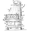
ここで図1を参照すると、キャノピ12が下方位置すなわち閉位置に配置された状態の、本発明に従って構成された乳児ケア装置10の側面図が示されている。示されるように、キャノピ12の位置において、乳児ケア装置10は、乳児保育器として働くことになり、乳児加温器と比較すると、乳児に対するアクセスは相対的に制限されているが、温度及び場合によっては湿度及び/又は酸素濃度が確立され、乳児の健康のためにこれらが慎重に維持されている制御された環境をもっている。
Referring now to FIG. 1, a side view of an infant care device 10 constructed in accordance with the present invention is shown with the
示されるように、乳児ケア装置10は、乳児の下にあって乳児を支持する乳児用プラットフォーム14を含む。同じく分かるように、乳児を乳児ケア装置10内に安全に収めるために、複数の壁16が設けられており、これらは乳児用プラットフォーム14の四辺の全てに配置される。壁16は、透明なプラスチック材料からなり、説明されるように、乳児ケア装置10が図1の構成である場合、保育器機能を与えるように他のコンポーネントと協働することが好ましい。
As shown, the infant care apparatus 10 includes an infant platform 14 that underlies and supports the infant. As can also be seen, a plurality of
対流加熱システムは、本発明と併せて用いることができ、強制空気対流を用いる公知の商業上のシステムとすることができ、用いることができる1つのこのようなシステムが、Mackin他の米国特許第6,213,936号に示され説明されており、加熱器、ファン、湿度制御、空気ダクトなどのような、対流加熱システムに必要な装置は、通常、乳児用プラットフォーム14内に配置される。この対流加熱システムは、当該キャノピ12が閉位置にあり、乳児ケア装置10が保育器機能を実行している場合に形成される乳児用コンパートメントを通して加熱空気を循環させる。
The convection heating system can be used in conjunction with the present invention and can be a known commercial system using forced air convection, and one such system that can be used is the Mackin et al. The devices necessary for the convection heating system, such as heaters, fans, humidity control, air ducts, etc., are typically located within the infant platform 14 as shown and described in US Pat. No. 6,213,936. The convection heating system circulates heated air through an infant compartment formed when the
乳児用プラットフォーム14は垂直ベース部材18に取り付けられ、該垂直ベース部材18は、好ましい実施形態においては、固定垂直ベース部材19に移動可能に固定され、該固定垂直ベース部材19は、乳児ケア装置10を容易に移動できるようにする車輪22を有するベース20に取り付けられる。
The infant platform 14 is attached to a
垂直ベース部材18は、ユーザが、必要に応じて該垂直ベース部材18を上げ下げすることによって乳児用プラットフォーム14の高さを調節できるように取り付けられることが好ましく、これにより該乳児用プラットフォーム14は、ユーザが好ましい高さに調節することができる。さらに標準的な特徴として、壁16は、図1の保育器構成の際に乳児へのアクセスを可能にする手挿入用穴24を有し、通常はドア26を有し、及び/又は該壁自体がドアとして働き、これらのドアは、乳児にアクセスするために開けることができ、もちろん特定の介入が終わったときに乳児を取り囲む所望の環境を保つために閉じることができる。
The
別の便利な特徴は、乳児に対して或る作業を行うのに必要な供給品その他の装置を保持する引き出し28を含み、この引き出し28は、通常は乳児用プラットフォーム14の下に位置する。他の特徴は、ベースが乳児用プラットフォームにピボット運動可能に取り付けられ、それにより壁16を外方にかつ下方に移動することができ、さらに別の態様としては乳児用プラットフォーム14から簡単に完全に取り去ることができるようにする、該壁16の操作性を含む。
したがって、それ故に、乳児ケア装置10のキャノピ12が、図1に示されるように閉位置にある際には、壁16は、看護人が乳児用プラットフォーム14に載せられている乳児にアクセスして、その乳児に対して介入を行えるように、下方に倒すか又は全て取り去ることができる。
Another convenient feature includes a
Therefore, when the
乳児ケア装置10の更に別の構造コンポーネントは、ベース部材18に取り付けられた垂直フレーム部材30(もちろん、1つより多い垂直フレーム部材があってもよい)を含む。垂直フレーム部材30に取り付けることができる制御モジュール(図示せず)があってもよく、該制御モジュールは、種々のモニタ用パラメータのディスプレイを含み、並びに乳児ケア装置10の機能の作動のための種々の制御を含むことができる。制御モジュールは、Falk他の米国特許第5,474,517号に示され説明されるものに類似するか、又はこれと同じものとすることができる。
放射加熱器34は、垂直フレーム部材30の上に配置され、乳児用プラットフォーム14に対して定位置でそこに保持されるので、該放射加熱器34は、常に、赤外線エネルギーを、該乳児用プラットフォーム14に位置された乳児の方向に向けるように合焦することができる。
Yet another structural component of the infant care apparatus 10 includes a vertical frame member 30 (of course, there may be more than one vertical frame member) attached to the
Since the
ここでキャノピ12を参照すると、キャノピ12は2つの部分すなわち第1の部分36及び第2の部分38で構成される。第1の部分36は、基本的にキャノピ12の一端の近く又は一端に配置されたピボット軸40において、乳児用プラットフォーム14に対してピボット運動可能に取り付けられている。キャノピ12の全体は、ここで用いられる便宜上キャノピ北端部42と呼ばれる端部を有し、このキャノピ北端部は、乳児ケア装置10の端部に位置しており、ここに垂直フレーム部材30が配置され、ここから放射加熱器34が延びている。
Referring now to the
通常は、その端部に制御モジュールが配置されており、よって制御の作業コンポーネント、モニタ、及び放射加熱器34を支持する構造コンポーネントが、乳児ケア装置10のプラットフォーム北端部44に配置され、キャノピ12と同様になっている。実際には、キャノピ北端部42もプラットフォーム北端44部も、通常は、乳児の頭部の向きである。
したがって、ピボット軸40の位置は、キャノピ北端部42か、又は該キャノピ北端部42の近くにあり、該ピボット軸40は、乳児用プラットフォーム14に対して固定され、ブラケット又は該ピボット軸40を定位置に保持する他の構造コンポーネントによって固定することができる。
Typically, a control module is located at the end, so that the control work components, the monitor, and the structural components that support the
Thus, the position of the
プラットフォーム南端部46及びキャノピ南端部48が、プラットフォーム北端部44の反対側に配置され、通常、乳児の足が該プラットフォーム南端部46及び該キャノピ南端部48の方向に向けられる。
示される実施形態においては、乳児用プラットフォーム14の構成全体及びキャノピ12がほぼ長方形であるので、プラットフォーム北端44部及びプラットフォーム南端部46は、共にこの長方形の辺の短辺であり、横方向の辺50は、該長方向の辺の長辺である。したがって、示される実施形態において、ピボット軸40は、乳児用プラットフォーム14及びキャノピ12の長方形の底面積の辺の短辺に沿っている。
明らかに、正方形の構成或いは円形又は弧状の底面積さえも含む、乳児用プラットフォーム14及び嵌合するキャノピ12の他の構成を本発明と共に用いることができ、該キャノピ12の一端又は一部が乳児用プラットフォーム14に対してピボット運動可能に取り付けられていることだけが重要である。
A platform south end 46 and a canopy south end 48 are positioned opposite the platform north end 44 and the infant's foot is typically oriented toward the platform south end 46 and the canopy
In the embodiment shown, the overall configuration of the infant platform 14 and the
Obviously, other configurations of the infant platform 14 and
このように、図1において、第2の部分38は、第1の部分36に対して移動可能であり、プラットフォーム北端部44の方向に摺動することができる。第2の部分38と第1の部分36との間の摺動関係は、2つの部分が接合された状態のまま実行され、この摺動関係は、第2の部分38及び第1の部分36の従来の重なっている又は連結している下縁部によって達成することができる。
ここで図1において理解できるように、乳児へのアクセスを得るために、或いは乳児ケア装置10を保育器のようなある機能から、乳児加温器及び赤外線エネルギーを乳児用プラットフォーム14の方向に向けるように活性化された放射加熱器34のようなある機能に変換するために、キャノピ南端部48を持ち上げることにより、ピボット軸40を中心にしてキャノピ12をピボット運動させることができる。
Thus, in FIG. 1, the
As can now be seen in FIG. 1, to direct the infant warmer and infrared energy toward the infant platform 14 to gain access to the infant or from some function such as an incubator, the infant care apparatus 10. The
しかしながら、乳児ケア装置10の寸法のために、キャノピ12が一部品構成又は中実の構成である場合には、該キャノピ12が開位置にピボット運動することにより、該キャノピ12が、該キャノピ12のピボット運動に対する障害物となる放射加熱器34にぶつかることになるので、該キャノピ12のピボット運動の角度が、該障害物によって制限される。このように、キャノピ12が放射加熱器34を越えてピボット運動することができないので、乳児ケア装置10が該放射加熱器34を活性化して乳児を暖めることを可能にするために、ピボット軸40を中心に該キャノピ12をピボット運動することが防止され、これにより該放射加熱器34から乳児用プラットフォーム14上に載せられている乳児への赤外線エネルギーの直接経路が妨げられる。
見られるように、キャノピ12のプラスチック材料を通過することなく、放射エネルギーを放射加熱器34から乳児用プラットフォーム14まで放出するために、該キャノピ12が、放射加熱器34まで、好ましくは該放射加熱器34を越えてピボット運動しなければならない。
However, due to the dimensions of the infant care apparatus 10, if the
As can be seen, in order to release radiant energy from the
ここで図2を参照すると、第2の部分38が、矢印Aの方向にキャノピ北端部42に向けて摺動され、これによりキャノピ12の横方向の辺の長さが短くなり、全体を52で示される開口部すなわちオープンスペースが形成されるようになった、乳児ケア装置10の側面図が示される。第2の部分38の後端部54は、長さが短くなった際に第1の部分36の内部に嵌め込まれるようになったが、下縁部の連結が、摺動関係で互いに取り付けられた第1の部分36及び第2の部分38を保持し続ける。図2の第1の部分36及び第2の部分38のこの位置においては、キャノピ12は、乳児へのアクセルを得ることができ、及び/又は乳児を暖めるために放射加熱器34を活性化することができる開位置にピボット運動できる状態にある。
Referring now to FIG. 2, the
ここで図3を参照すると、キャノピ12が開位置にピボット運動された本乳児ケア装置10の側面図がある。この図において、キャノピ12は、矢印Bの方向にピボット軸40を中心としてピボット運動され、第1の部分36の方向への第2の部分38の相対的な移動によりもたらされた短くなった長さのため、該キャノピ12が放射加熱器34を越えてピボット運動でき、その障害物が回避され、該キャノピ12をほぼ垂直な配向角度までピボット運動できるので、該放射加熱器34による放射を、該キャノピ12を通過することなく、乳児用プラットフォーム14の方向に向けることができる。
示されるように、ユーザが単にキャノピ南端部48を持ち上げることにより、キャノピ12のピボット運動を手動で実行することができるが、代替的な実施形態においては、キャノピ12が開位置と閉位置との間で移動する際に、該キャノピ12のピボット運動を実行するために、小型のDC又はステッパモータのようなモータ56があってもよい。
Referring now to FIG. 3, there is a side view of the infant care apparatus 10 with the
As shown, the user can manually perform a pivoting movement of the
次に、図4を参照すると、代替的な実施形態の側面図が示されており、多くのコンポーネントが、図1乃至図3の実施形態におけるものと同じであり、同じ番号で識別された。この実施形態において、キャノピ12の第1の部分36は、同じくピボット軸40によって、乳児用プラットフォーム14に対してピボット運動可能に取り付けられており、このピボット軸40は、キャノピ12北端部42又は該キャノピ北端部の近くに配置されている。従来の実施形態と同様に、単にピボット軸40を中心としてキャノピ南端部48を持ち上げることにより、乳児へのアクセスのために、又は乳児ケア装置10を乳児加温器機能に変換するために、キャノピを上昇させることができる。
しかしながら、この実施形態を用いる場合、キャノピの第2の部分38は、キャノピ12内に形成された落とし戸60であり、図4において閉位置の状態で示される。落とし戸60は、ピボット軸を形成するヒンジ62によって、キャノピ12の第1の部分36にピボット運動可能に取り付けられている。落とし戸60は、閉位置の方向に付勢され、ばね64によってその閉位置に保持されている。
Referring now to FIG. 4, a side view of an alternative embodiment is shown, with many components being the same as in the embodiment of FIGS. 1-3 and identified with the same numbers. In this embodiment, the
However, when using this embodiment, the
したがって、図5を参照すると、キャノピ12が開位置の状態で示された、図4の実施形態の乳児ケア装置10の側面図が示される。図示されるように、キャノピ12の上昇又はピボット運動により、該キャノピ12が障害物にぶつかる位置すなわち放射加熱器34まで移動された。キャノピ12が障害物にぶつかると、落とし戸60が、ばね64の付勢に抗してその開位置に押し付けられるので、放射加熱器34は、実際に該落とし戸60の開口部によって生じた開口部すなわちスペース66に入り、該スペース66を通過することができる。1つの落とし戸60だけが示されるが、本発明の精神と一致するように用いられる複数の落とし戸があってもよい。
したがって、図1乃至図3の実施形態と同様に、放射加熱器34によって放射された放射エネルギーが、乳児用プラットフォーム14に向けられ、キャノピ12の存在によって妨げられないことを可能にするように、該キャノピ12を十分に開けることができる。
Accordingly, referring to FIG. 5, a side view of the infant care apparatus 10 of the embodiment of FIG. 4 is shown with the
Thus, similar to the embodiment of FIGS. 1-3, to allow the radiant energy radiated by the
従来の実施形態と同様に、本発明のキャノピ12を手動で開閉できるが、該キャノピ12を開位置と閉位置との間で移動させるように活性化できるモータ66を設けてもよく、さらに、モータ68によって落とし戸60を開閉することもできる。したがって、この故に、キャノピ12及び落とし戸60の作動は、ユーザによって自動的に制御することができ、通常、落とし戸60は、放射加熱器34にぶつかる前にモータ68によって開けられる。
As with the conventional embodiment, the
当業者であれば、本発明の乳児ケア装置になし得る多くの適応及び修正と、その結果として乳児ケア装置のための改良されたテレメトリ・システムが得られることと、またその全てが上記の特許請求の範囲において定められた本発明の範囲及び精神内に入ることを直ちに認識するであろう。したがって、本発明は、上記の特許請求の範囲の請求項及びそれらの均等物によってのみ限定されるものである。 One of ordinary skill in the art will be able to make many adaptations and modifications to the infant care device of the present invention, resulting in an improved telemetry system for the infant care device, and all of which are described above. It will be readily recognized that it is within the scope and spirit of the invention as defined in the claims. Accordingly, the invention is limited only by the following claims and their equivalents.
10:乳児ケア装置
12:キャノピ
14:乳児用プラットフォーム
16:壁
34:放射加熱器
36:第1の部分
38:第2の部分
40:ピボット軸
60:落とし戸
64:ばね
68:モータ
10: baby care device 12: canopy 14: baby platform 16: wall 34: radiant heater 36: first part 38: second part 40: pivot shaft 60: trap door 64: spring 68: motor
Claims (10)
乳児用プラットフォームと前記乳児用プラットフォームの上方に垂直方向に変位して配置された障害物とを有し、さらに、前記乳児用プラットフォームの上に取り付けられ、該乳児用コンパートメント内で乳児を内部に囲む、第1の部分及び第2の部分を有するキャノピを含む乳児加温器を準備し、
前記乳児用プラットフォームの端部の一方の近くに配置された軸に沿って、該乳児用プラットフォームに対して前記第1の部分をピボット運動可能に取り付け、前記キャノピが、前記乳児用コンパートメントが形成される第1の位置と該乳児用プラットフォーム上に載せられている乳児にアクセス可能な第2の位置との間で前記軸の周りをピボット運動することを可能にし、
前記キャノピ内にオープンスペースを形成するように、該キャノピの前記第2の部分を前記第1の部分に対して配置し、
前記オープンスペースを前記障害物と位置合わせし、
前記キャノピを、前記障害物を越えて開位置まで移動させる、
段階を含むことを特徴とする方法。 A method of using an infant warming device,
An infant platform and an obstacle vertically displaced above the infant platform, further mounted on the infant platform and enclosing the infant within the infant compartment Preparing an infant warmer including a canopy having a first portion and a second portion;
The first portion is pivotally attached to the infant platform along an axis disposed near one of the ends of the infant platform, the canopy is formed with the infant compartment. Enabling pivoting about said axis between a first position and a second position accessible to an infant resting on said infant platform;
Placing the second portion of the canopy relative to the first portion so as to form an open space in the canopy;
Align the open space with the obstacle,
Moving the canopy over the obstacle to an open position;
A method comprising steps.
Applications Claiming Priority (1)
| Application Number | Priority Date | Filing Date | Title |
|---|---|---|---|
| US10/736,660 US6893390B1 (en) | 2003-12-16 | 2003-12-16 | Movable canopy for infant care apparatus |
Publications (1)
| Publication Number | Publication Date |
|---|---|
| JP2005177480A true JP2005177480A (en) | 2005-07-07 |
Family
ID=34523129
Family Applications (1)
| Application Number | Title | Priority Date | Filing Date |
|---|---|---|---|
| JP2004362722A Pending JP2005177480A (en) | 2003-12-16 | 2004-12-15 | Movable canopy for infant care apparatus |
Country Status (4)
| Country | Link |
|---|---|
| US (1) | US6893390B1 (en) |
| EP (1) | EP1543808A3 (en) |
| JP (1) | JP2005177480A (en) |
| CA (1) | CA2488286A1 (en) |
Cited By (1)
| Publication number | Priority date | Publication date | Assignee | Title |
|---|---|---|---|---|
| JP2011502726A (en) * | 2007-12-04 | 2011-01-27 | ドレーゲル メディカル システムズ,インコーポレイテッド | Warming treatment device having a retractable hood member |
Families Citing this family (9)
| Publication number | Priority date | Publication date | Assignee | Title |
|---|---|---|---|---|
| GB2431353A (en) * | 2005-10-18 | 2007-04-25 | Shailinder Jit Singh | Multipurpose incubator |
| JP5283477B2 (en) * | 2008-10-23 | 2013-09-04 | アトムメディカル株式会社 | Incubator |
| JP5297879B2 (en) * | 2009-05-08 | 2013-09-25 | アトムメディカル株式会社 | Child care equipment |
| DE102012006204B4 (en) * | 2012-03-27 | 2016-04-28 | Drägerwerk AG & Co. KGaA | Thermotherapy device |
| DE102016006371B4 (en) * | 2016-05-30 | 2023-03-09 | Drägerwerk AG & Co. KGaA | Device for aligning and connecting a hood to a housing |
| US11141104B2 (en) | 2017-06-22 | 2021-10-12 | General Electric Company | Infant warming system having ECG monitor and method for providing resuscitation assistance |
| US10596054B2 (en) | 2017-06-28 | 2020-03-24 | General Electric Company | Infant warming system and method |
| US11564373B2 (en) * | 2019-05-14 | 2023-01-31 | Farrpro, Inc. | System and method for heating animals |
| CN114053050B (en) * | 2021-11-16 | 2023-04-07 | 四川省妇幼保健院 | Body temperature monitoring nursing device for pediatrics department |
Citations (5)
| Publication number | Priority date | Publication date | Assignee | Title |
|---|---|---|---|---|
| JPS645549A (en) * | 1987-05-15 | 1989-01-10 | Boc Group Inc | Newborn nursing device having air curtain |
| US5308310A (en) * | 1992-08-18 | 1994-05-03 | Vitaltrends Technology, Inc. | Plethysmograph system and air-tight sealing assembly therefor |
| US5474517A (en) * | 1994-08-15 | 1995-12-12 | Ohmeda Inc. | Heater assembly for infant warmers |
| JP2001008984A (en) * | 1999-05-21 | 2001-01-16 | Datex Ohmeda Inc | Actuating mechanism for heater door for infant caring apparatus |
| US20010049465A1 (en) * | 1993-12-17 | 2001-12-06 | Charles Goldberg | Patient thermal support device |
Family Cites Families (5)
| Publication number | Priority date | Publication date | Assignee | Title |
|---|---|---|---|---|
| US3858570A (en) | 1972-06-12 | 1975-01-07 | Puritan Bennett Corp | Comprehensive infant care system |
| IL75215A (en) | 1985-05-16 | 1992-07-15 | Israel Atomic Energy Comm | Infant incubator |
| US6709384B1 (en) | 1993-12-17 | 2004-03-23 | Hill-Rom Services, Inc. | Infant thermal support device |
| US6022310A (en) * | 1997-09-09 | 2000-02-08 | Hill-Rom, Inc. | Canopy adjustment mechanisms for thermal support apparatus |
| US6213935B1 (en) | 1999-12-11 | 2001-04-10 | Datex-Ohmeda, Inc. | Infant warming apparatus |
-
2003
- 2003-12-16 US US10/736,660 patent/US6893390B1/en not_active Expired - Fee Related
-
2004
- 2004-11-24 CA CA002488286A patent/CA2488286A1/en not_active Abandoned
- 2004-12-01 EP EP04257476A patent/EP1543808A3/en not_active Withdrawn
- 2004-12-15 JP JP2004362722A patent/JP2005177480A/en active Pending
Patent Citations (8)
| Publication number | Priority date | Publication date | Assignee | Title |
|---|---|---|---|---|
| JPS645549A (en) * | 1987-05-15 | 1989-01-10 | Boc Group Inc | Newborn nursing device having air curtain |
| US5308310A (en) * | 1992-08-18 | 1994-05-03 | Vitaltrends Technology, Inc. | Plethysmograph system and air-tight sealing assembly therefor |
| US20010049465A1 (en) * | 1993-12-17 | 2001-12-06 | Charles Goldberg | Patient thermal support device |
| US5474517A (en) * | 1994-08-15 | 1995-12-12 | Ohmeda Inc. | Heater assembly for infant warmers |
| JPH08178313A (en) * | 1994-08-15 | 1996-07-12 | Ohmeda Inc | Heater assembly for infant heating apparatus |
| JP3357375B2 (en) * | 1995-09-25 | 2002-12-16 | ヒル−ロム,インコーポレイティド | Thermal support equipment for the sick |
| JP2001008984A (en) * | 1999-05-21 | 2001-01-16 | Datex Ohmeda Inc | Actuating mechanism for heater door for infant caring apparatus |
| US6224539B1 (en) * | 1999-05-21 | 2001-05-01 | Datex-Ohmeda, Inc. | Heater door mechanism for infant warming apparatus |
Cited By (2)
| Publication number | Priority date | Publication date | Assignee | Title |
|---|---|---|---|---|
| JP2011502726A (en) * | 2007-12-04 | 2011-01-27 | ドレーゲル メディカル システムズ,インコーポレイテッド | Warming treatment device having a retractable hood member |
| US8602963B2 (en) | 2007-12-04 | 2013-12-10 | Draeger Medical Systems, Inc. | Warming therapy device including retractable hood member |
Also Published As
| Publication number | Publication date |
|---|---|
| EP1543808A3 (en) | 2006-02-08 |
| US6893390B1 (en) | 2005-05-17 |
| CA2488286A1 (en) | 2005-06-16 |
| EP1543808A2 (en) | 2005-06-22 |
Similar Documents
| Publication | Publication Date | Title |
|---|---|---|
| JP5232281B2 (en) | Infant care equipment | |
| US7282022B2 (en) | Infant care apparatus with fixed overhead heater | |
| US6213935B1 (en) | Infant warming apparatus | |
| JP2000041795A (en) | Rotary type mattress for baby | |
| JP2005177480A (en) | Movable canopy for infant care apparatus | |
| US6471634B1 (en) | Infant care apparatus with bidirectional sliding drawer | |
| US6506147B2 (en) | Movable canopy warmer for an infant care unit | |
| US6905457B2 (en) | Radiant field management for infant care apparatus | |
| US6611978B1 (en) | Patient-support apparatus | |
| US6880188B1 (en) | Infant care apparatus with movable infant support | |
| US7108653B2 (en) | Canopy adjustable mounting system for infant warming apparatus | |
| JPS6128596Y2 (en) | ||
| US6953427B1 (en) | Infant care apparatus with object detection sensing | |
| US20220296447A1 (en) | Patient care device with retractable heater element | |
| BRPI1106266A2 (en) | hospital equipment, which operates as an incubator or heated crib, with a heater positioning system |
Legal Events
| Date | Code | Title | Description |
|---|---|---|---|
| A621 | Written request for application examination |
Free format text: JAPANESE INTERMEDIATE CODE: A621 Effective date: 20071214 |
|
| A131 | Notification of reasons for refusal |
Free format text: JAPANESE INTERMEDIATE CODE: A131 Effective date: 20091214 |
|
| A521 | Written amendment |
Free format text: JAPANESE INTERMEDIATE CODE: A523 Effective date: 20100315 |
|
| A02 | Decision of refusal |
Free format text: JAPANESE INTERMEDIATE CODE: A02 Effective date: 20100412 |