JP2005172027A - Linear guide bearing device - Google Patents
Linear guide bearing device Download PDFInfo
- Publication number
- JP2005172027A JP2005172027A JP2003408976A JP2003408976A JP2005172027A JP 2005172027 A JP2005172027 A JP 2005172027A JP 2003408976 A JP2003408976 A JP 2003408976A JP 2003408976 A JP2003408976 A JP 2003408976A JP 2005172027 A JP2005172027 A JP 2005172027A
- Authority
- JP
- Japan
- Prior art keywords
- return guide
- guide
- end cap
- cap body
- return
- Prior art date
- Legal status (The legal status is an assumption and is not a legal conclusion. Google has not performed a legal analysis and makes no representation as to the accuracy of the status listed.)
- Pending
Links
Images


Landscapes
- Bearings For Parts Moving Linearly (AREA)
Abstract
Description
本発明は、例えば工作機械や射出成形機等の産業機械分野等に用いられる直動案内軸受装置に関する。 The present invention relates to a linear motion guide bearing device used in an industrial machine field such as a machine tool or an injection molding machine.
従来のこの種の直動案内軸受装置としては、例えば図29に示すものが知られている。 この直動案内軸受装置は、軸方向に延びる案内レール1と、該案内レール1上に軸方向に相対移動可能に跨架されたスライダ2とを備えている。
案内レール1の幅方向の両側面にはそれぞれ軸方向に延びる転動体転動溝3が片側上下二条列ずつ、合計4条列形成されており、スライダ2のスライダ本体2Aには、その両袖部4の内側面にそれぞれ転動体転動溝3に対向する転動体転動溝5が片側上下二条列ずつ、合計4条列形成されている。
As a conventional linear guide bearing device of this type, for example, the one shown in FIG. 29 is known. This linear motion guide bearing device includes a guide rail 1 extending in the axial direction and a
On both side surfaces of the guide rail 1 in the width direction, rolling
両転動体転動溝3,5の間には転動体としての多数の円筒ころ6が転動自在に装填され、これらの円筒ころ6の転動を介してスライダ2が案内レール1上を軸方向に沿って相対移動できるようになっている。
この移動につれて、案内レール1とスライダ2との間に介在する円筒ころ6は転動してスライダ2の軸方向の端部に移動するが、スライダ2を軸方向に継続移動させていくためには、これらの円筒ころ6を無限に循環させる必要がある。
A large number of
Along with this movement, the
このため、スライダ本体2Aの両袖部4内に軸方向に貫通する孔7を片側上下2箇所ずつ、合計4箇所形成して該孔7に内部が円筒ころ6の通路(転動体通路)8aとされた循環スリーブ8を嵌め込むと共に、スライダ本体2Aの軸方向の両端にそれぞれ転動体循環部品としての一対のエンドキャップ9をねじ等を介して固定し、このエンドキャップ9に上記両転動体転動溝3,5間と上記転動体通路8aとを連通する円弧状に湾曲した方向転換路10(図30参照)を形成することにより、円筒ころ6の無限循環軌道を形成している。
For this reason,
エンドキャップ9は、図30に示すように、エンドキャップ本体9aと、該エンドキャップ9の前記スライダ本体2Aの端面を向く側に軸方向に嵌め込まれる第1のリターンガイド30及び第2のリターンガイド40とを備える。
第1のリターンガイド30と第2のリターンガイド40は共に外形形状が略同形の板状部材とされており、互いに対向する平行な接合面及び外側面に方向転換路10を形成するための凹凸や穴が複数設けられている。第1のリターンガイド30と第2のリターンガイド40との各接合面同士を外形形状が略一致するように凹凸嵌合し、この状態で第1のリターンガイド30側がエンドキャップ本体9aに軸方向に嵌合される(例えば特許文献1参照)。
As shown in FIG. 30, the
Both the
そして、この例では、第1のリターンガイド30、第2のリターンガイド40及びエンドキャップ本体9aによって上側の転動体通路8aと下側の両転動体転動溝3,5間とを連通する方向転換路10を形成し、第1のリターンガイド30と第2のリターンガイド40とによって下側の転動体通路8aと上側の両転動体転動溝3,5間とを連通する方向転換路10を形成している。
ところで、無限循環する多数の円筒ころ6はころ軸を中心に同一方向に回転するため、互いに隣り合う円筒ころ6同士が接触した場合、その接触部分のころ速度の向きは互いに逆方向になり、それにより発生する力は円筒ころ6の円滑な転動を妨げることになる。
In this example, the
By the way, since many
また、転動体に円筒ころ6を使用することで、ボールを使用する場合に比べて剛性及び負荷能力が高くなる反面、走行中の円筒ころ6の軸振れ、いわゆるスキューが発生して作動性を悪化させる要因になる。
このような事情から、従来においては、互いに隣り合う円筒ころ6間にセパレータ20を介装することで、円筒ころ同士の直接接触を防止すると共に、前記スキューを抑制し、これにより、スライダ2の走行を滑らかにすると共に、走行中の騒音低減を図るようにしている。
In addition, the use of the
Under such circumstances, conventionally, by interposing the
セパレータ20は、図31〜図33に示すように、互いに隣り合う円筒ころ6間に介装されるセパレータ本体21と、該円筒ころ6の軸方向の両端面を挟むように配置されて前記セパレータ本体21と一体に設けられた腕部22とを備えており、セパレータ本体21の円筒ころ6の外周面に対向する部分には該円筒ころ6の外周形状に応じた凹曲面21aが形成されている。なお、図29において符号23は案内レール1の外側面とスライダ2の内側面との間に配置されたセパレータ案内部材である。
As shown in FIGS. 31 to 33, the
そして、両転動体転動溝3,5間、方向転換路10及び転動体通路8aを円筒ころ6が循環する際には、セパレータ20の腕部22は、前記セパレータ案内部材23、前記転動体通路8a及び前記方向転換路10にそれぞれ設けられた案内溝24によって円筒ころ6の循環方向に沿って案内されるようになっている。
しかしながら、上記従来の直動案内軸受装置においては、第1のリターンガイド30と第2のリターンガイド40が共に外形形状が複雑で且つ略同形の板状部材とされて、互いに対向する平行な接合面及び外側面に方向転換路10を形成するための凹凸や穴が複数設けられているため、形状が複雑となって高い成形精度が要求されるばかりか、第1のリターンガイド30と第2のリターンガイド40との各接合面同士を外形形状が略一致するように凹凸嵌合する作業が面倒なため組立作業の効率が悪く、製造コストが高くつく。
However, in the above-described conventional linear motion guide bearing device, the
また、エンドキャップ本体9a、第1のリターンガイド30及び第2のリターンガイド40を互いに略平行に分割した構造となるため、方向転換路10のころ軌道溝をころ軸方向に横切るような分割面が多くなり(第1のリターンガイド30と第2のリターンガイド40との分割面で2箇所、第1のリターンガイド30とエンドキャップ本体9aとの分割面で1箇所、合計3箇所)、この結果、分割面の接合部分での段差数が多くなって円筒ころ6の案内精度が悪化し、作動性に悪影響を及ぼす可能性がある。
本発明はこのような不都合を解消するためになされたものであり、第1のリターンガイドと第2のリターンガイドとの嵌合作業を簡単にして組立作業の効率化、ひいては製造コストの低コスト化を図ることができると共に、方向転換路のころ軌道溝の段差数を減らして作動性の向上を図ることができる直動案内軸受装置を提供することを目的とする。
Further, since the end cap
The present invention has been made in order to eliminate such inconveniences. The fitting work between the first return guide and the second return guide is simplified to improve the efficiency of the assembling work, and the manufacturing cost is low. An object of the present invention is to provide a linear motion guide bearing device that can improve the operability by reducing the number of steps of the roller raceway grooves on the direction change path.
上記目的を達成するために、請求項1に係る発明は、両側部に軸方向に延びる転動体転動溝を有する案内レールと、該案内レールの前記転動体転動溝に対向する転動体転動溝を有し、これらの両転動体転動溝間に挿入された転動体としての多数のころの転動を介して軸方向に沿って相対移動可能に前記案内レールに跨架されたスライダとを備え、
前記スライダは、軸方向に貫通する転動体通路を有するスライダ本体と、前記両転動体転動溝間と前記転動体通路とを連通する湾曲状の方向転換路を有して前記スライダ本体の軸方向の両端面に固定された一対のエンドキャップとを具備し、
前記両転動体転動溝が片側上下二条列で合計4条列とされると共に前記転動体通路が片側上下二つずつで合計4つとされた直動案内軸受装置において、
前記エンドキャップは、エンドキャップ本体と、該エンドキャップ本体の前記スライダ本体の端面を向く側に軸方向に嵌め込まれた第1のリターンガイドと、該第1のリターンガイドに軸方向に嵌め込まれた第2のリターンガイドとを備え、
前記第1のリターンガイドと前記第2のリターンガイドとは軸方向から見て短辺側に前記ころの軌道溝が設けられた略長方形状をなして互いに略直交配置され、前記第1のリターンガイドと前記エンドキャップ本体とによって上側の前記転動体通路と下側の前記両転動体転動溝間とを連通する方向転換路及び下側の前記転動体通路と上側の前記両転動体転動溝間とを連通する方向転換路の内のいずれか一方の方向転換路を形成すると共に、前記第2のリターンガイド、前記エンドキャップ本体及び前記第1のリターンガイドによって他方の方向転換路を形成することを特徴とする。
In order to achieve the above object, the invention according to claim 1 is directed to a guide rail having rolling element rolling grooves extending in the axial direction on both sides, and a rolling element rolling member facing the rolling element rolling grooves of the guide rail. A slider having a moving groove and straddling the guide rail so as to be relatively movable along the axial direction through rolling of a large number of rollers as rolling elements inserted between the rolling grooves of both the rolling elements. And
The slider has a slider body having a rolling element passage penetrating in the axial direction, and a curved direction changing path that communicates between the rolling element rolling grooves and the rolling element passage. A pair of end caps fixed to both end faces of the direction,
In the linear guide bearing device in which the rolling element rolling grooves are arranged in a total of four rows in two rows on one side and a total of four rolling element passages in two on the one side.
The end cap is fitted into the end cap body, a first return guide fitted in the axial direction on the side of the end cap body facing the end surface of the slider body, and fitted in the first return guide in the axial direction. A second return guide,
The first return guide and the second return guide are arranged in a substantially rectangular shape in which a raceway groove of the roller is provided on the short side when viewed from the axial direction, and are arranged substantially orthogonal to each other. A direction changing path for communicating between the upper rolling element passage and the lower rolling element rolling grooves by the guide and the end cap body, and the lower rolling element path and the upper rolling element rolling. One of the direction change paths communicating with the grooves is formed, and the other direction change path is formed by the second return guide, the end cap body, and the first return guide. It is characterized by doing.
請求項2に係る発明は、請求項1において、前記第1のリターンガイドと前記エンドキャップ本体とによって形成される前記方向転換路の内周側のころ軌道溝を該第1のリターンガイドに設けると共に、該方向転換路の外周側のころ軌道溝を前記エンドキャップ本体に設け、
前記第2のリターンガイド、前記エンドキャップ本体及び前記第1のリターンガイドによって形成される前記方向転換路の内周側のころ軌道溝を該第2のリターンガイドに設けると共に、該方向転換路の外周側のころ軌道溝を前記エンドキャップ本体及び前記第1のリターンガイドに設けたことを特徴とする。
According to a second aspect of the present invention, in the first aspect, the first return guide is provided with a roller raceway groove on the inner peripheral side of the direction change path formed by the first return guide and the end cap body. A roller raceway groove on the outer periphery side of the direction changing path is provided in the end cap body,
A roller raceway groove on the inner peripheral side of the direction change path formed by the second return guide, the end cap body and the first return guide is provided in the second return guide, and the direction change path A roller raceway groove on the outer peripheral side is provided in the end cap body and the first return guide.
請求項3に係る発明は、請求項1又は2において、互いに隣り合う前記ころ間に介装されたセパレータ本体及び該ころの軸方向の少なくとも一方の端面に面するように配置されて前記セパレータ本体と一体に設けられた腕部を有するセパレータを備え、
前記両転動体転動溝間、前記方向転換路及び前記転動体通路を前記ころが循環する際に前記セパレータの前記腕部を前記ころの循環方向に沿って案内する案内溝を設けると共に、前記エンドキャップ本体、前記第1のリターンガイド及び前記第2のリターンガイドに前記案内溝の一部を形成する支持壁を設けたことを特徴とする。
The invention according to
A guide groove for guiding the arm portion of the separator along the circulation direction of the roller when the roller circulates between the rolling element rolling grooves, the direction changing path and the rolling element passage; The end cap body, the first return guide, and the second return guide are provided with support walls that form a part of the guide groove.
請求項4に係る発明は、請求項3において、前記第1のリターンガイドと前記エンドキャップ本体とによって形成される前記方向転換路に設けられた前記案内溝の内周支持壁を該第1のリターンガイドに設けると共に、該案内溝の外周支持壁を前記エンドキャップ本体に設け、
前記第2のリターンガイド、前記エンドキャップ本体及び前記第1のリターンガイドによって形成される前記方向転換路に設けられた前記案内溝の内周支持壁を該第2のリターンガイドに設けると共に、該案内溝の外周支持壁を前記エンドキャップ本体及び前記第1のリターンガイドに設けたことを特徴とする。
According to a fourth aspect of the present invention, in the third aspect, the inner peripheral support wall of the guide groove provided in the direction change path formed by the first return guide and the end cap main body is provided on the first return guide. Provided on the return guide, and provided with an outer peripheral support wall of the guide groove on the end cap body,
An inner peripheral support wall of the guide groove provided in the direction change path formed by the second return guide, the end cap body and the first return guide is provided in the second return guide, An outer peripheral support wall of a guide groove is provided in the end cap body and the first return guide.
請求項5に係る発明は、請求項4において、前記第1のリターンガイドと前記エンドキャップ本体とによって形成される前記方向転換路に設けられた前記案内溝の底面を前記エンドキャップ本体側に設け、
前記第1のリターンガイドと前記エンドキャップ本体との分割面を、該第1のリターンガイド側の前記内周側のころ軌道溝のころ軸方向延長面又は前記第1のリターンガイド側の案内溝の内周支持壁面のころ軸方向延長面としたことを特徴とする。
According to a fifth aspect of the present invention, in the fourth aspect, the bottom surface of the guide groove provided in the direction changing path formed by the first return guide and the end cap body is provided on the end cap body side. ,
A split surface between the first return guide and the end cap body is formed by extending a roller axial direction surface of the inner circumferential roller raceway groove on the first return guide side or a guide groove on the first return guide side. The inner peripheral support wall surface of the roller is an extension surface in the roller axial direction.
請求項6に係る発明は、請求項4において、前記第1のリターンガイドと前記エンドキャップ本体とによって形成される前記方向転換路に設けられた前記案内溝の底面を該第1のリターンガイド側に設け、
前記第1のリターンガイドと前記エンドキャップ本体との分割面を、前記エンドキャップ本体側の前記外周側のころ軌道溝のころ軸方向延長面又は該エンドキャップ本体側の前記案内溝の外周支持壁面のころ軸方向延長面としたことを特徴とする。
According to a sixth aspect of the present invention, in the fourth aspect, the bottom surface of the guide groove provided in the direction changing path formed by the first return guide and the end cap body is formed on the first return guide side. Provided in
A dividing surface between the first return guide and the end cap body is defined by a roller axially extending surface of the roller raceway groove on the outer peripheral side on the end cap body side or an outer peripheral support wall surface of the guide groove on the end cap body side. It is characterized by having a roller axially extending surface.
請求項7に係る発明は、請求項5又は6において、前記エンドキャップ本体と前記第1のリターンガイドとの分割面を該第1のリターンガイドの前記エンドキャップ本体に対する位置決め面及び/又は係止面としたことを特徴とする。
請求項8に係る発明は、請求項3〜7のいずれか一項において、前記第2のリターンガイド、前記エンドキャップ本体及び前記第1のリターンガイドによって形成される前記方向転換路に設けられた前記案内溝の底面を前記エンドキャップ本体側及び前記第1のリターンガイド側に設け、
前記第2のリターンガイドと前記第1のリターンガイドとの分割面を、該第2のリターンガイド側の前記内周側のころ軌道溝のころ軸方向延長面又は前記第2のリターンガイド側の前記案内溝の内周支持壁面のころ軸方向延長面としたことを特徴とする。
According to a seventh aspect of the present invention, in the fifth or sixth aspect, the split surface of the end cap body and the first return guide is a positioning surface and / or locking of the first return guide with respect to the end cap body. It is characterized by having a surface.
The invention according to
A split surface between the second return guide and the first return guide is defined by a roller axial extension surface of the inner circumferential roller raceway groove on the second return guide side or the second return guide side. A roller axially extending surface of an inner peripheral supporting wall surface of the guide groove is characterized in that
請求項9に係る発明は、請求項3〜7のいずれか一項において、前記第2のリターンガイド、前記エンドキャップ本体及び前記第1のリターンガイドによって形成される前記方向転換路に設けられた前記案内溝の底面を前記第2のリターンガイド側に設け、
前記第2のリターンガイドと前記第1のリターンガイドとの分割面を、該第1のリターンガイドの前記外周側のころ軌道溝のころ軸方向延長面又は前記第1のリターンガイドの前記案内溝の外周支持壁面のころ軸軸方向延長面としたことを特徴とする。
請求項10に係る発明は、請求項8又は9において、前記第2のリターンガイドと前記第1のリターンガイドとの分割面を該第2のリターンガイドの前記第1のリターンガイドに対する位置決め面及び/又は係止面としたことを特徴とする。
The invention according to
A split surface between the second return guide and the first return guide is defined as a roller axial extension surface of the roller raceway groove on the outer peripheral side of the first return guide or the guide groove of the first return guide. The outer circumferential support wall surface of the roller is an axially extended surface.
The invention according to
本発明によれば、第1のリターンガイドと第2のリターンガイドとがスライダ本体の軸方向から見て短辺側にころの軌道溝が設けられた略長方形状をなして互いに略直交配置されているので、第1のリターンガイド及び第2のリターンガイドの形状が簡単になって高い成形精度の要求を回避することができると共に、第1のリターンガイドと第2のリターンガイドとの軸方向の嵌合作業を容易に行うことができ、これにより、組立作業の効率化、ひいては製造コストの低コスト化を図ることができる。 According to the present invention, the first return guide and the second return guide are arranged substantially orthogonal to each other in a substantially rectangular shape in which the raceway groove of the roller is provided on the short side when viewed from the axial direction of the slider body. Therefore, the shape of the first return guide and the second return guide can be simplified to avoid the requirement for high molding accuracy, and the axial direction of the first return guide and the second return guide can be avoided. This makes it possible to easily perform the fitting operation, thereby making it possible to improve the efficiency of the assembling operation and hence to reduce the manufacturing cost.
また、第1のリターンガイドとエンドキャップ本体とによって形成される方向転換路の内周側のころ軌道溝を該第1のリターンガイドに設けると共に、該方向転換路の外周側のころ軌道溝をエンドキャップ本体に設け、第2のリターンガイド、エンドキャップ本体及び前記第1のリターンガイドによって形成される方向転換路の内周側のころ軌道溝を該第2のリターンガイドに設けると共に、該方向転換路の外周側のころ軌道溝をエンドキャップ本体及び第1のリターンガイドに設けることで、第2のリターンガイド、エンドキャップ本体及び前記第1のリターンガイドによって形成される方向転換路の外周側のころ軌道溝にころ軸方向に横切る分割面が2箇所形成されるに留めることができるので、分割面の接合部分での段差数が従来に比べて減少し、この結果、ころの案内精度が向上して作動性の向上を図ることができる。
更に、互いに隣り合うころ間にセパレータを介装した場合には、方向転換路でセパレータの腕部を循環方向に案内する案内溝についても、前記ころ軌道溝の場合と同様に、分割面の接合部分での段差数を減らすことができるので、セパレータの腕部の案内精度が向上して作動性の向上を図ることができる。
In addition, a roller raceway groove on the inner periphery side of the direction change path formed by the first return guide and the end cap body is provided in the first return guide, and a roller raceway groove on the outer periphery side of the direction change path is provided. A roller raceway groove on the inner peripheral side of the direction change path formed by the second return guide, the end cap body, and the first return guide is provided in the second return guide, By providing a roller raceway groove on the outer peripheral side of the conversion path in the end cap main body and the first return guide, the outer peripheral side of the direction change path formed by the second return guide, the end cap main body and the first return guide. Since the roller raceway groove can be formed with only two split surfaces that cross in the roller axial direction, the number of steps at the junction of the split surfaces is lower than in the conventional case. It decreased Te, as a result, it is possible to improve the operability by improving guidance accuracy of the roller.
Further, when a separator is interposed between the rollers adjacent to each other, the guide groove for guiding the arm portion of the separator in the direction of circulation in the direction change path is also joined to the divided surface as in the case of the roller raceway groove. Since the number of steps at the portion can be reduced, the guide accuracy of the arm portion of the separator can be improved and the operability can be improved.
以下、本発明の実施の形態の一例を図を参照して説明する。
図1は本発明の実施の形態の一例である直動案内軸受装置の要部を説明するための説明図、図2は図1の矢印A方向から見た内部構造の説明図、図3はエンドキャップ本体のスライダ本体の端面側を向く面を示す図、図4は図3のA−A線断面図、図5は図3のB−B線断面図、図6は第1のリターンガイドをスライダ本体の端面側から軸方向(嵌合方向)に見た図、図7は図6の右側面図、図8は図6のA−A線断面図、図9は第2のリターンガイドをスライダ本体の端面側から軸方向(嵌合方向)に見た図、図10は図9の右側面図、図11は図9の底面図、図12はエンドキャップ本体、第1のリターンガイド及び第2のリターンガイドの嵌合構造を示す断面図、図13は図12の矢印A方向から見た内部構造を示す断面図、図14は第1のリターンガイドと第2のリターンガイドとの嵌合前の状態を示す図、図15は第1のリターンガイドと第2のリターンガイドとが嵌合された状態を示す図、図16は図15の矢印A方向から見た図、図17は第1のリターンガイドに第2のリターンガイドを嵌合した状態で第1のリターンガイドをエンドキャップ本体に嵌合した状態を示す図、図18は第1のリターンガイドと第2のリターンガイドとの分割位置及び第1のリターンガイドとエンドキャップ本体との分割位置を説明するための断面図、図19〜図28はエンドキャップ本体、第1のリターンガイド及び第2のリターンガイドの嵌合構造の変形例を示す断面図である。
Hereinafter, an example of an embodiment of the present invention will be described with reference to the drawings.
FIG. 1 is an explanatory diagram for explaining a main part of a linear guide bearing device which is an example of an embodiment of the present invention, FIG. 2 is an explanatory diagram of an internal structure viewed from the direction of arrow A in FIG. 1, and FIG. FIG. 4 is a cross-sectional view taken along line AA in FIG. 3, FIG. 5 is a cross-sectional view taken along line BB in FIG. 3, and FIG. 6 is a first return guide. FIG. 7 is a right side view of FIG. 6, FIG. 8 is a cross-sectional view taken along line AA of FIG. 6, and FIG. 9 is a second return guide. FIG. 10 is a right side view of FIG. 9, FIG. 11 is a bottom view of FIG. 9, FIG. 12 is an end cap body, and a first return guide. And FIG. 13 is a cross-sectional view showing the internal structure seen from the direction of arrow A in FIG. 12, and FIG. 14 is a cross-sectional view showing the fitting structure of the second return guide. FIG. 15 shows a state before the first return guide and the second return guide are fitted together, FIG. 15 shows a state where the first return guide and the second return guide are fitted, and FIG. 15 is a view seen from the direction of arrow A, FIG. 17 is a view showing a state in which the first return guide is fitted to the end cap body in a state where the second return guide is fitted to the first return guide, and FIG. FIG. 19 to FIG. 28 are sectional views for explaining the division position of the first return guide and the second return guide and the division position of the first return guide and the end cap body. FIGS. It is sectional drawing which shows the modification of the fitting structure of this return guide and a 2nd return guide.
なお、この実施の形態では、既に図29で説明した従来の直動案内軸受装置と基本的構造が同一のものを例に採り、重複する部分については各図に同一符号を付してその説明を省略する。
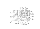
本発明の実施の形態の一例である直動案内軸受装置は、図1及び図2に示すように、スライダ本体2Aの端面に固定されるエンドキャップ50が、エンドキャップ本体50aと、該エンドキャップ本体50aのスライダ本体2Aの端面を向く側に軸方向に嵌め込まれた第1のリターンガイド60と、該第1のリターンガイド60に軸方向に嵌め込まれた第2のリターンガイド70とを備えており、第1のリターンガイド60と第2のリターンガイド70とは、軸方向から見て短辺側に円筒ころ6の内周側軌道溝6aが設けられた略長方形状をなして互いに略直交配置されている。
In this embodiment, the same basic structure as that of the conventional linear motion guide bearing device already described with reference to FIG. 29 is taken as an example, and overlapping portions are denoted by the same reference numerals in the respective drawings. Is omitted.
As shown in FIGS. 1 and 2, a linear guide bearing device that is an example of an embodiment of the present invention includes an
そして、この実施の形態では、第1のリターンガイド60とエンドキャップ本体50aとによって上側の転動体通路8aと下側の両転動体転動溝3,5間とを連通する方向転換路10aを形成し、第2のリターンガイド70、第1のリターンガイド60及びエンドキャップ本体50aによって下側の転動体通路8aと上側の両転動体転動溝3,5間とを連通する方向転換路10bを形成している。
In this embodiment, the
第1のリターンガイド60は、図6〜図8に示すように、略U字形状をなしてその周方向両端部がスライダ本体2Aの軸方向から見て長手方向に対向配置されており、U字状の外周面に沿って方向転換路10aの内周側ころ軌道溝6aが形成されると共に、内周面側の底部に方向転換路10bの外周側ころ軌道溝6b(図8参照)の一部が前記内周側ころ軌道溝6aに対して略直交するように形成されている。
そして、第1のリターンガイド60の外周面側の底部がエンドキャップ本体50aに形成された嵌合凹部51に軸方向に嵌合されている。
As shown in FIGS. 6 to 8, the
And the bottom part of the outer peripheral surface side of the
嵌合凹部51は、図3〜図5に示すように、第1のリターンガイド60の形状に対応してエンドキャップ本体50aのスライダ本体2Aの端面側を向く面に略U字状に凹設されており、該嵌合凹部51のU字状の底面に沿って方向転換路10aの外周側ころ軌道溝6bが形成されている。
この嵌合凹部51の外周側ころ軌道溝6bと第1のリターンガイド60の内周側ころ軌道溝6aとによって上側の転動体通路8aと下側の両転動体転動溝3,5間とを連通する方向転換路10aが形成される。
As shown in FIGS. 3 to 5, the
By the outer peripheral side
また、エンドキャップ本体50aには嵌合凹部51より浅いU字凹部52が該嵌合凹部51に対して略直交するように形成されており、該U字凹部52の底部には方向転換路10bの外周側ころ軌道溝6bが上述した第1のリターンガイド60の内周面側の底部に部分的に形成された方向転換路10bの外周側ころ軌道溝6bと面一で接続されるように形成されている。
第2のリターンガイド70は、図9〜図10に示すように、スライダ本体2Aの軸方向寸法が第1のリターンガイド60より短い略円弧形状をなしてその周方向両端部がスライダ本体2Aの軸方向から見て長手方向に対向配置されており、円弧状の外周面に沿って方向転換路10bの内周側ころ軌道溝6aが形成されている。
Further, a
As shown in FIGS. 9 to 10, the
そして、第2のリターンガイド70の外周面側の底部が第1のリターンガイド60の内周側にその長手方向が第1のリターンガイド60の長手方向に対して略直交するように軸方向に嵌合され、かかる嵌合状態においては、第2のリターンガイド70の外周側の内周側ころ軌道溝6aと、エンドキャップ本体50aのU字凹部52の底部に形成された外周側ころ軌道溝6b及び第1のリターンガイド60の内周面側の底部に部分的に形成された外周側ころ軌道溝6bとによって、下側の転動体通路8aと上側の両転動体転動溝3,5間とを連通する方向転換路10bが方向転換路10aに対して立体交差するように形成される。
Then, the bottom of the
ここで、この実施の形態では、エンドキャップ本体50aのU字凹部52の底部に形成された外周側ころ軌道溝6bと第1のリターンガイド60の内周面側の底部に部分的に形成された外周側ころ軌道溝6bとの接続部に、外周側ころ軌道溝6bをころ軸方向に横切る分割面55が2箇所形成される。
なお、エンドキャップ本体50a、第1のリターンガイド60及び第2のリターンガイド70の嵌合手順は、図14〜図17に示すように、第1のリターンガイド60と第2のリターンガイド70とを嵌合した後に、第1のリターンガイド60をエンドキャップ本体50aの嵌合凹部51に嵌合してもよいし、エンドキャップ本体50aの嵌合凹部51に第1のリターンガイド60を嵌合した後に、該第1のリターンガイド60に第2のリターンガイド70を嵌合するようにしてもよい。
Here, in this embodiment, it is partially formed on the outer peripheral side
The end cap
次に、方向転換路10a,10bに設けられるセパレータ20の腕部22の案内溝24について説明する。
第1のリターンガイド60の外周側に設けられた内周側ころ軌道溝6aのころ軸方向両側には、方向転換路10aに設けられる案内溝24の内周支持壁24aが第1のリターンガイド60のU字状外周面に沿って形成され、第1のリターンガイド60の内周側底部に設けられた外周側ころ軌道溝6bのころ軸方向の両側には、方向転換路10bに設けられる案内溝24の外周支持壁24bが形成され、第2のリターンガイド70の外周側に設けられた内周側ころ軌道溝6aのころ軸方向両側には、方向転換路10bに設けられる案内溝24の内周支持壁24aが第2のリターンガイド70の円弧状外周面に沿って形成されている。
Next, the
On the both sides in the roller axial direction of the inner peripheral
また、エンドキャップ本体50aの嵌合凹部51に設けられた外周側ころ軌道溝6bのころ軸方向両側には、方向転換路10aに設けられる案内溝24の外周支持壁24bが嵌合凹部51のU字形状に沿って形成され、エンドキャップ本体50aのU字凹部52に設けられた外周側ころ軌道溝6bのころ軸方向両側には、方向転換路10bに設けられる案内溝24の外周支持壁24bが第1のリターンガイド60の内周側底部に設けられた外周支持壁24bと面一で接続されるように形成されている。従って、案内溝24についても、エンドキャップ本体50aのU字凹部52に設けられた外周支持壁24bと第1のリターンガイド60の内周側底部に設けられた外周支持壁24bとの接続部に、分割面55が2箇所形成される。
In addition, on the both sides in the roller axial direction of the outer peripheral
ここで、この実施の形態では、図12に示すように、方向転換路10aに設けられる案内溝24の底面24cをエンドキャップ本体50aに設けると共に、第1のリターンガイド60とエンドキャップ本体50aとの分割面を該第1のリターンガイド60の内周側ころ軌道溝6aのころ軸方向延長面80(図18参照)とし、図12の第1のリターンガイド60のエンドキャップ本体50aに対する上下方向の位置決め面及び係止面を前記内周側ころ軌道溝6aのころ軸方向延長面80とすると共に、図12の第1のリターンガイド60の左右方向の位置決め面及び係止面を第1のリターンガイド60の側面81(図18参照)又は第1のリターンガイド60のU字状外周面に沿って形成された案内溝24の内周支持壁24aの外側面82(図18参照)としている。
In this embodiment, as shown in FIG. 12, the
また、図13に示すように、方向転換路10bに設けられる案内溝24の底面24cを第1のリターンガイド60の内周側の底部及びエンドキャップ本体50aのU字凹部52に設けると共に、第2のリターンガイド70と第1のリターンガイド60との分割面を該第2のリターンガイド70の内周側ころ軌道溝6aのころ軸方向延長面80(図18参照)とし、図13の第2のリターンガイド70の第1のリターンガイド60に対する上下方向の位置決め面及び係止面を前記内周側ころ軌道溝6aのころ軸方向延長面80とすると共に、図13の第2のリターンガイド70の左右方向の位置決め面及び係止面を第2のリターンガイド70の側面81(図18参照)又は第2のリターンガイド70の円弧状外周面に沿って形成された案内溝24の内周支持壁24aの外側面82(図18参照)としている。
Further, as shown in FIG. 13, the
上記の説明から明らかなように、この実施の形態では、エンドキャップ本体50aの嵌合凹部51に軸方向に嵌合される第1のリターンガイド60と、該第1のリターンガイド60に軸方向に嵌合される第2のリターンガイド70とがスライダ本体2Aの軸方向から見て短辺側にころ軌道溝6aが設けられた略長方形状をなして互いに略直交配置されているので、第1のリターンガイド60及び第2のリターンガイド70の形状が簡単になって高い成形精度の要求が回避されると共に、第1のリターンガイド60と第2のリターンガイド70との軸方向の嵌合作業を容易に行うことができ、これにより、組立作業の効率化、ひいては製造コストの低コスト化を図ることができる。
As is apparent from the above description, in this embodiment, the
また、第2のリターンガイド70、エンドキャップ本体50a及び第1のリターンガイド60によって形成される方向転換路10bの外周側のころ軌道溝6bにころ軸方向に横切る分割面55が2箇所形成されるに留めることができるので、分割面55の接合部分での段差数が従来に比べて減少し、この結果、ころの案内精度が向上して作動性の向上を図ることができる。
更に、方向転換路10bでセパレータ20の腕部22を循環方向に案内する案内溝24についても、前記ころ軌道溝6bの場合と同様に、分割面55の接合部分での段差数を減らすことができるので、セパレータ20の腕部22の案内精度が向上して作動性の向上を図ることができる。
なお、本発明の直動案内軸受装置は上記実施の形態に限定されるものではなく、本発明の要旨を逸脱しない範囲において適宜変更可能である。
Further, two split
Further, with respect to the
The linear guide bearing device of the present invention is not limited to the above-described embodiment, and can be appropriately changed without departing from the gist of the present invention.
例えば、上記実施の形態では、第1のリターンガイド60とエンドキャップ本体50aとによって上側の転動体通路8aと下側の両転動体転動溝3,5間とを連通する方向転換路10aを形成し、第2のリターンガイド70、第1のリターンガイド60及びエンドキャップ本体50aによって下側の転動体通路8aと上側の両転動体転動溝3,5間とを連通する方向転換路10bを形成した場合を例に採ったが、これに代えて、第1のリターンガイド60とエンドキャップ本体50aとによって下側の転動体通路8aと上側の両転動体転動溝3,5間とを連通する方向転換路10bを形成し、第2のリターンガイド70、第1のリターンガイド60及びエンドキャップ本体50aによって上側の転動体通路8aと下側の両転動体転動溝3,5間とを連通する方向転換路10aを形成するようにしてもよい。
For example, in the above-described embodiment, the direction change
また、上記実施の形態では、第1のリターンガイド60の外周側に方向転換路10aを形成する内周側ころ軌道溝6aを全て設けた場合を例に採ったが、必ずしもこのようにする必要はなく、例えば図19に示すように、第2のリターンガイド70に方向転換路10aを形成する内周側ころ軌道溝6aの一部を設けるようにしてもよい。
以下、図20〜図28を参照して、エンドキャップ本体50a、第1のリターンガイド及び第2のリターンガイドの嵌合構造の変形例を説明する。
In the above embodiment, the case where all the inner peripheral
Hereinafter, modified examples of the fitting structure of the
図20は、エンドキャップ本体50aと第1のリターンガイド60との嵌合構造の変形例を示すもので、この例では、方向転換路10aに設けられた案内溝24の底面24cをエンドキャップ本体50aに設けると共に、第1のリターンガイド60とエンドキャップ本体50aとの分割面を該第1のリターンガイド60に設けた案内溝24の内周支持壁24aのころ軸方向延長面83(図18参照)とし、図20の第1のリターンガイド60のエンドキャップ本体50aに対する上下方向の位置決め面及び係止面を前記内周支持壁24aのころ軸方向延長面83とすると共に、図20の第1のリターンガイド60の左右方向の位置決め面及び係止面を第1のリターンガイド60の側面81(図18参照)としている。
FIG. 20 shows a modification of the fitting structure between the
図21は、第1のリターンガイド60と第2のリターンガイド70との嵌合構造の変形例を示すもので、この例では、方向転換路10bに設けられた案内溝24の底面24cを第1のリターンガイド60の内周側の底部及びエンドキャップ本体50aのU字凹部52に設けると共に、第2のリターンガイド70と第1のリターンガイド60との分割面を該第2のリターンガイド70に設けた案内溝24の内周支持壁24aのころ軸方向延長面83(図18参照)とし、図21の第2のリターンガイド70の第1のリターンガイド60に対する上下方向の位置決め面及び係止面を内周支持壁24aのころ軸方向延長面83とすると共に、図21の第2のリターンガイド70の左右方向の位置決め面及び係止面を第2のリターンガイド70の側面81(図18参照)としている。なお、図22は、第2のリターンガイド70に方向転換路10aを形成する内周側ころ軌道溝6aの一部を設けた例である。
FIG. 21 shows a modified example of the fitting structure of the
図23は、エンドキャップ本体50aと第1のリターンガイド60との嵌合構造の変形例を示すもので、この例では、方向転換路10aに設けられた案内溝24の底面24cを第1のリターンガイド60に設けると共に、第1のリターンガイド60とエンドキャップ本体50aとの分割面をエンドキャップ本体50aの嵌合凹部51に設けた案内溝24の外周支持壁24bのころ軸方向延長面84(図18参照)とし、図23の第1のリターンガイド60のエンドキャップ本体50aに対する上下方向の位置決め面及び係止面を前記案内溝24の外周支持壁24bのころ軸方向延長面84とすると共に、図23の第1のリターンガイド60の左右方向の位置決め面及び係止面を第1のリターンガイド60の側面81(図18参照)としている。
FIG. 23 shows a modification of the fitting structure between the
図24は、第1のリターンガイド60と第2のリターンガイド70との嵌合構造の変形例を示すもので、この例では、方向転換路10bに設けられた案内溝24の底面24cを第2のリターンガイド70に設けると共に、第2のリターンガイド70と第1のリターンガイド60との分割面を第1のリターンガイド60に設けた案内溝24の外周支持壁24bのころ軸方向延長面84(図18参照)とし、図24の第2のリターンガイド70の第1のリターンガイド60に対する上下方向の位置決め面及び係止面を前記外周支持壁24bのころ軸方向延長面84とすると共に、図24の第2のリターンガイド70の左右方向の位置決め面及び係止面を第2のリターンガイド70の側面81(図18参照)としている。なお、図25は、第2のリターンガイド70に方向転換路10aを形成する内周側ころ軌道溝6aの一部を設けた例である。
FIG. 24 shows a modified example of the fitting structure of the
図26は、エンドキャップ本体50aと第1のリターンガイド60との嵌合構造の変形例を示すもので、この例では、方向転換路10aに設けられた案内溝24の底面24cを第1のリターンガイド60に設けると共に、第1のリターンガイド60とエンドキャップ本体50aとの分割面をエンドキャップ本体50aの嵌合凹部51に設けた外周側ころ軌道溝6bのころ軸方向延長面85(図18参照)とし、図26の第1のリターンガイド60のエンドキャップ本体50aに対する上下方向の位置決め面及び係止面を前記外周側ころ軌道溝6bのころ軸方向延長面85とすると共に、図26の第1のリターンガイド60の左右方向の位置決め面及び係止面を第1のリターンガイド60の側面81(図18参照)又はエンドキャップ本体50aの嵌合凹部51に設けられた案内溝24の外周支持壁24bの外側面85(図18参照)としている。
FIG. 26 shows a modification of the fitting structure between the
図27は、第1のリターンガイド60と第2のリターンガイド70との嵌合構造の変形例を示すもので、この例では、方向転換路10bに設けられた案内溝24の底面24cを第2のリターンガイド70に設けると共に、第2のリターンガイド70と第1のリターンガイド60との分割面を第1のリターンガイド60の外周側ころ軌道溝6bのころ軸方向延長面85(図18参照)とし、図27の第2のリターンガイド70の第1のリターンガイド60に対する上下方向の位置決め面及び係止面を前記外周側ころ軌道溝6bのころ軸方向延長面85とすると共に、図23の第2のリターンガイド70の左右方向の位置決め面及び係止面を第2のリターンガイド70の側面81(図18参照)又は第1のリターンガイド60に形成された案内溝24の外周支持壁24bの外側面86(図18参照)としている。なお、図28は、第2のリターンガイド70に方向転換路10aを形成する内周側ころ軌道溝6aの一部を設けた例である。
FIG. 27 shows a modified example of the fitting structure of the
1 案内レール
2 スライダ
2A スライダ本体
3 転動体転動溝(案内レール側)
5 転動体転動溝(スライダ側)
6 円筒ころ
6a 内周側ころ軌道溝
6b 外周側ころ軌道溝
8a 転動体通路
10a,10b 方向転換路
20 セパレータ
21 セパレータ本体
22 腕部
24 案内溝
24a 案内溝の内周支持壁
24b 案内溝の外周支持壁
24c 案内溝の底面
50 エンドキャップ
50a エンドキャップ本体
60 第1のリターンガイド
70 第2のリターンガイド
80 内周側ころ軌道溝のころ軸方向延長面
83 案内溝の内周支持壁面のころ軸方向延長面
84 案内溝の外周支持壁面のころ軸方向延長面
85 外周側ころ軌道溝のころ軸方向延長面
1
5 Rolling element rolling groove (slider side)
6
Claims (10)
前記スライダは、軸方向に貫通する転動体通路を有するスライダ本体と、前記両転動体転動溝間と前記転動体通路とを連通する湾曲状の方向転換路を有して前記スライダ本体の軸方向の両端面に固定された一対のエンドキャップとを具備し、
前記両転動体転動溝が片側上下二条列で合計4条列とされると共に前記転動体通路が片側上下二つずつで合計4つとされた直動案内軸受装置において、
前記エンドキャップは、エンドキャップ本体と、該エンドキャップ本体の前記スライダ本体の端面を向く側に軸方向に嵌め込まれる第1のリターンガイドと、該第1のリターンガイドに軸方向に嵌め込まれる第2のリターンガイドとを備え、
前記第1のリターンガイドと前記第2のリターンガイドとは軸方向から見て短辺側に前記ころの軌道溝が設けられた略長方形状をなして互いに略直交配置され、前記第1のリターンガイドと前記エンドキャップ本体とによって上側の前記転動体通路と下側の前記両転動体転動溝間とを連通する方向転換路及び下側の前記転動体通路と上側の前記両転動体転動溝間とを連通する方向転換路の内のいずれか一方の方向転換路を形成すると共に、前記第2のリターンガイド、前記エンドキャップ本体及び前記第1のリターンガイドによって他方の方向転換路を形成することを特徴とする直動案内軸受装置。 A guide rail having axially extending rolling element rolling grooves on both sides, and a rolling element rolling groove facing the rolling element rolling groove of the guide rail, and between the rolling element rolling grooves. A slider straddling the guide rail so as to be relatively movable along the axial direction through rolling of a large number of rollers as inserted rolling elements,
The slider has a slider body having a rolling element passage penetrating in the axial direction, and a curved direction changing path that communicates between the rolling element rolling grooves and the rolling element passage. A pair of end caps fixed to both end faces of the direction,
In the linear guide bearing device in which the rolling element rolling grooves are arranged in a total of four rows in two rows on one side and a total of four rolling element passages in two on the one side.
The end cap includes an end cap body, a first return guide fitted in the axial direction on the side of the end cap body facing the end face of the slider body, and a second return guide fitted in the first return guide in the axial direction. With a return guide,
The first return guide and the second return guide are arranged in a substantially rectangular shape in which a raceway groove of the roller is provided on the short side when viewed from the axial direction, and are arranged substantially orthogonal to each other. A direction changing path for communicating between the upper rolling element passage and the lower rolling element rolling grooves by the guide and the end cap body, and the lower rolling element path and the upper rolling element rolling. One of the direction change paths communicating with the grooves is formed, and the other direction change path is formed by the second return guide, the end cap body, and the first return guide. A linear motion guide bearing device comprising:
前記第2のリターンガイド、前記エンドキャップ本体及び前記第1のリターンガイドによって形成される前記方向転換路の内周側のころ軌道溝を該第2のリターンガイドに設けると共に、該方向転換路の外周側のころ軌道溝を前記エンドキャップ本体及び前記第1のリターンガイドに設けたことを特徴とする請求項1に記載した直動案内軸受装置。 A roller raceway groove on the inner peripheral side of the direction changing path formed by the first return guide and the end cap body is provided in the first return guide, and a roller raceway groove on the outer peripheral side of the direction change path. Is provided on the end cap body,
A roller raceway groove on the inner peripheral side of the direction change path formed by the second return guide, the end cap body and the first return guide is provided in the second return guide, and the direction change path The linear guide bearing device according to claim 1, wherein a roller raceway groove on an outer peripheral side is provided in the end cap body and the first return guide.
前記両転動体転動溝間、前記方向転換路及び前記転動体通路を前記ころが循環する際に前記セパレータの前記腕部を前記ころの循環方向に沿って案内する案内溝を設けると共に、前記エンドキャップ本体、前記第1のリターンガイド及び前記第2のリターンガイドに前記案内溝の一部を形成する支持壁を設けたことを特徴とする請求項1又は2に記載した直動案内軸受装置。 A separator body interposed between the rollers adjacent to each other, and a separator having an arm portion disposed so as to face at least one end face in the axial direction of the rollers and provided integrally with the separator body,
A guide groove for guiding the arm portion of the separator along the circulation direction of the roller when the roller circulates between the rolling element rolling grooves, the direction changing path and the rolling element passage; The linear guide bearing device according to claim 1, wherein a support wall that forms a part of the guide groove is provided in an end cap body, the first return guide, and the second return guide. .
前記第2のリターンガイド、前記エンドキャップ本体及び前記第1のリターンガイドによって形成される前記方向転換路に設けられた前記案内溝の内周支持壁を該第2のリターンガイドに設けると共に、該案内溝の外周支持壁を前記エンドキャップ本体及び前記第1のリターンガイドに設けたことを特徴とする請求項3に記載した直動案内軸受装置。 An inner peripheral support wall of the guide groove provided in the direction change path formed by the first return guide and the end cap body is provided in the first return guide, and an outer peripheral support wall of the guide groove. Is provided on the end cap body,
An inner peripheral support wall of the guide groove provided in the direction change path formed by the second return guide, the end cap body and the first return guide is provided in the second return guide, 4. The linear guide bearing device according to claim 3, wherein an outer peripheral support wall of a guide groove is provided in the end cap body and the first return guide.
前記第1のリターンガイドと前記エンドキャップ本体との分割面を、該第1のリターンガイド側の前記内周側のころ軌道溝のころ軸方向延長面又は前記第1のリターンガイド側の案内溝の内周支持壁面のころ軸方向延長面としたことを特徴とする請求項4に記載した直動案内軸受装置。 A bottom surface of the guide groove provided in the direction change path formed by the first return guide and the end cap body is provided on the end cap body side;
A split surface between the first return guide and the end cap body is formed by extending a roller axial direction surface of the inner circumferential roller raceway groove on the first return guide side or a guide groove on the first return guide side. The linear motion guide bearing device according to claim 4, wherein the inner peripheral support wall surface is a roller axially extending surface.
前記第1のリターンガイドと前記エンドキャップ本体との分割面を、前記エンドキャップ本体側の前記外周側のころ軌道溝のころ軸方向延長面又は該エンドキャップ本体側の前記案内溝の外周支持壁面のころ軸方向延長面としたことを特徴とする請求項4に記載した直動案内軸受装置。 A bottom surface of the guide groove provided in the direction change path formed by the first return guide and the end cap body is provided on the first return guide side;
A dividing surface between the first return guide and the end cap body is defined by a roller axially extending surface of the roller raceway groove on the outer peripheral side on the end cap body side or an outer peripheral support wall surface of the guide groove on the end cap body side. The linear motion guide bearing device according to claim 4, wherein the roller axial extension surface is provided.
前記第2のリターンガイドと前記第1のリターンガイドとの分割面を、該第2のリターンガイド側の前記内周側のころ軌道溝のころ軸方向延長面又は前記第2のリターンガイド側の前記案内溝の内周支持壁面のころ軸方向延長面としたことを特徴とする請求項3〜7のいずれか一項に記載した直動案内軸受装置。 The bottom surface of the guide groove provided in the direction change path formed by the second return guide, the end cap body, and the first return guide is formed on the end cap body side and the first return guide side. Provided,
A split surface between the second return guide and the first return guide is defined by a roller axial extension surface of the inner circumferential roller raceway groove on the second return guide side or the second return guide side. The linear motion guide bearing device according to any one of claims 3 to 7, wherein the guide groove is an extension surface in the roller axial direction of an inner peripheral support wall surface of the guide groove.
前記第2のリターンガイドと前記第1のリターンガイドとの分割面を、該第1のリターンガイドの前記外周側のころ軌道溝のころ軸方向延長面又は前記第1のリターンガイドの前記案内溝の外周支持壁面のころ軸軸方向延長面としたことを特徴とする請求項3〜7のいずれか一項に記載した直動案内軸受装置。 A bottom surface of the guide groove provided in the direction change path formed by the second return guide, the end cap body and the first return guide is provided on the second return guide side;
A split surface between the second return guide and the first return guide is defined as a roller axial extension surface of the roller raceway groove on the outer peripheral side of the first return guide or the guide groove of the first return guide. The linear guide bearing device according to any one of claims 3 to 7, characterized in that the outer peripheral support wall surface is a roller axial direction extending surface.
Priority Applications (3)
| Application Number | Priority Date | Filing Date | Title |
|---|---|---|---|
| JP2003408976A JP2005172027A (en) | 2003-12-08 | 2003-12-08 | Linear guide bearing device |
| US10/797,109 US7465093B2 (en) | 2003-03-13 | 2004-03-11 | Linear guide apparatus |
| EP04005871A EP1457693A2 (en) | 2003-03-13 | 2004-03-11 | Linear guide apparatus |
Applications Claiming Priority (1)
| Application Number | Priority Date | Filing Date | Title |
|---|---|---|---|
| JP2003408976A JP2005172027A (en) | 2003-12-08 | 2003-12-08 | Linear guide bearing device |
Publications (2)
| Publication Number | Publication Date |
|---|---|
| JP2005172027A true JP2005172027A (en) | 2005-06-30 |
| JP2005172027A5 JP2005172027A5 (en) | 2006-11-09 |
Family
ID=34730504
Family Applications (1)
| Application Number | Title | Priority Date | Filing Date |
|---|---|---|---|
| JP2003408976A Pending JP2005172027A (en) | 2003-03-13 | 2003-12-08 | Linear guide bearing device |
Country Status (1)
| Country | Link |
|---|---|
| JP (1) | JP2005172027A (en) |
Cited By (1)
| Publication number | Priority date | Publication date | Assignee | Title |
|---|---|---|---|---|
| WO2023203932A1 (en) * | 2022-04-20 | 2023-10-26 | Thk株式会社 | Motion guide device |
Citations (3)
| Publication number | Priority date | Publication date | Assignee | Title |
|---|---|---|---|---|
| JPS48104943U (en) * | 1972-03-16 | 1973-12-06 | ||
| JPH05209617A (en) * | 1992-01-31 | 1993-08-20 | Nippon Thompson Co Ltd | Direct-acting rolling guide unit |
| WO2001092738A1 (en) * | 2000-05-29 | 2001-12-06 | Thk Co., Ltd. | Linear motion guide device |
-
2003
- 2003-12-08 JP JP2003408976A patent/JP2005172027A/en active Pending
Patent Citations (3)
| Publication number | Priority date | Publication date | Assignee | Title |
|---|---|---|---|---|
| JPS48104943U (en) * | 1972-03-16 | 1973-12-06 | ||
| JPH05209617A (en) * | 1992-01-31 | 1993-08-20 | Nippon Thompson Co Ltd | Direct-acting rolling guide unit |
| WO2001092738A1 (en) * | 2000-05-29 | 2001-12-06 | Thk Co., Ltd. | Linear motion guide device |
Cited By (1)
| Publication number | Priority date | Publication date | Assignee | Title |
|---|---|---|---|---|
| WO2023203932A1 (en) * | 2022-04-20 | 2023-10-26 | Thk株式会社 | Motion guide device |
Similar Documents
| Publication | Publication Date | Title |
|---|---|---|
| EP1326026B1 (en) | Linear motion guide unit with separator between any two adjoining rolling elements | |
| JP4537588B2 (en) | Linear motion guidance unit | |
| JP4493103B2 (en) | Exercise guidance device | |
| JP4285286B2 (en) | Linear motion guide bearing device | |
| US7465093B2 (en) | Linear guide apparatus | |
| JP2003278752A (en) | Direct action guide unit interposing separator between roller | |
| US20070223846A1 (en) | Ball spline | |
| JP2005172027A (en) | Linear guide bearing device | |
| JP2006234032A (en) | Linear guide bearing device | |
| JP4635735B2 (en) | Linear motion guide bearing device | |
| JP4305162B2 (en) | Linear motion guide bearing device | |
| JP2005180580A (en) | Linear guide bearing device | |
| JP5222609B2 (en) | Rolling body circuit structure and exercise device | |
| JP5810596B2 (en) | Linear guide device | |
| JP2006002870A (en) | Straight motion guide bearing device | |
| JP5909848B2 (en) | Linear motion guide bearing device | |
| JP2012082879A (en) | Motion guide device | |
| JP5604889B2 (en) | Sliding tripod type constant velocity joint | |
| JP2008309227A (en) | Linear guide | |
| JP2009058072A (en) | Motion apparatus and its manufacturing method | |
| JP2005016553A (en) | Linear motion guide bearing device | |
| JP2007120528A (en) | Linear guide bearing device | |
| JP2005163909A (en) | Linear guide bearing device | |
| JP2005155788A (en) | Linear guide bearing device | |
| KR20230149844A (en) | Direct guidance device |
Legal Events
| Date | Code | Title | Description |
|---|---|---|---|
| A521 | Written amendment |
Free format text: JAPANESE INTERMEDIATE CODE: A523 Effective date: 20060927 |
|
| A621 | Written request for application examination |
Free format text: JAPANESE INTERMEDIATE CODE: A621 Effective date: 20060927 |
|
| A977 | Report on retrieval |
Free format text: JAPANESE INTERMEDIATE CODE: A971007 Effective date: 20090402 |
|
| A131 | Notification of reasons for refusal |
Free format text: JAPANESE INTERMEDIATE CODE: A131 Effective date: 20091208 |
|
| A02 | Decision of refusal |
Free format text: JAPANESE INTERMEDIATE CODE: A02 Effective date: 20100406 |