JP2005166312A - Contact device - Google Patents
Contact device Download PDFInfo
- Publication number
- JP2005166312A JP2005166312A JP2003400483A JP2003400483A JP2005166312A JP 2005166312 A JP2005166312 A JP 2005166312A JP 2003400483 A JP2003400483 A JP 2003400483A JP 2003400483 A JP2003400483 A JP 2003400483A JP 2005166312 A JP2005166312 A JP 2005166312A
- Authority
- JP
- Japan
- Prior art keywords
- contact
- contact portion
- intermediate body
- contacted
- elastic member
- Prior art date
- Legal status (The legal status is an assumption and is not a legal conclusion. Google has not performed a legal analysis and makes no representation as to the accuracy of the status listed.)
- Granted
Links
Images
Landscapes
- Support Of Aerials (AREA)
- Details Of Aerials (AREA)
Abstract
【課題】接点装置の接点部の耐摩耗性を向上しつつ、より確実な導通を確保する。
【解決手段】接点部16は、基体部12に装着された弾性部材14によって上方に付勢され、被当接体に押しつけられる。中間体18は、基体部12に設けられたガイド孔34にガイドされて所定区間内で被当接体に対して接離自在となるとともに、弾性部材14に直接的に付勢されることなく接点部16と係合して、接点部16の可動範囲を規制する。中間体18はガイド孔34に緩装される。
【選択図】図3[PROBLEMS] To secure more reliable conduction while improving the wear resistance of a contact portion of a contact device.
A contact portion 16 is urged upward by an elastic member 14 attached to a base portion 12 and pressed against a contacted body. The intermediate body 18 is guided by a guide hole 34 provided in the base portion 12 so that the intermediate body 18 can be brought into and out of contact with the contacted body within a predetermined section, and is not directly biased by the elastic member 14. The movable portion of the contact portion 16 is restricted by engaging with the contact portion 16. The intermediate body 18 is loosely mounted in the guide hole 34.
[Selection] Figure 3
Description
本発明は、弾性部材を用いて接点部材を被当接体に押し当てる構成を有する接点装置に関する。 The present invention relates to a contact device having a configuration in which a contact member is pressed against a contacted body using an elastic member.
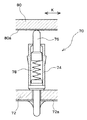
図9に、従来の接点装置70を示す。この接点装置70は、二つの部品等の間で導通を確保する場合に、その接続部分に用いられる。図9の接点装置70は、一方の部品72に固定される固定部74と、固定部74内に移動自在に収容され導体からなる可動接触子76と、同じく固定部74内に移動自在に収容され導体からなるスプリング78と、を備える。可動接触子76は、スプリング78によって付勢され、もう一方の部品80の導体パターン80aに当接される。そして、スプリング78、可動接触子76、および固定部74が導通路として機能し、二つの部品72,80間(各々に設けられる導体パターン72a,80a間)で導通が確保される。この種の接点装置は、二つの部品間で電気的な接続のための結線作業が不要になるというメリットがあり、特に、二つの部品間の距離が変動したり、個体差(ばらつき)があったりする場合に有効である。この種の接点装置としては、例えば特許文献1に開示されるものが知られている。
FIG. 9 shows a
上記従来の接点装置で、例えば、二つの部品を組み付けるとき等、可動接触子と被当接体とが軸方向と垂直な方向(図9の矢印Kの方向)にずれる可能性がある場合においては、可動接触子と被当接体との擦れる距離を短くすべく、可動接触子にある程度の傾きを許容しつつ、可動接触子の先端(当接端)を丸めることで、その傾斜によらずより安定的な導通が得られるようにすることがあった。 In the above conventional contact device, for example, when assembling two parts, the movable contact and the contacted body may be displaced in the direction perpendicular to the axial direction (the direction of the arrow K in FIG. 9). In order to shorten the rubbing distance between the movable contact and the abutted body, the movable contact is allowed to be tilted to some extent while the tip of the movable contact (contact end) is rounded, so that In some cases, more stable conduction was obtained.
しかしながら、その構成では、可動接触子の先端を丸めて被当接体との接触面積が小さくなる分、接触抵抗が大きくなったり、また、面圧が高くなることで、可動接触子の先端あるいは被当接体が摩耗しやすくなるという問題があった。 However, in the configuration, the tip of the movable contact is increased by rounding the tip of the movable contact to reduce the contact area with the contacted body, and the contact resistance is increased or the surface pressure is increased. There was a problem that the contacted body was easily worn.
かといって、可動接触子の傾斜を抑制すると、上記ずれが生じたときには、傾斜が許容される場合に比べて、被当接体と擦れる距離が長くなり、この場合も、可動接触子の先端あるいは被当接体が摩耗してしまうことがある。また、可動接触子の先端を平面状に形成すると、可動接触子の僅かな傾きによっても当該平面で被当接体と接触することができなくなる場合があり、所望の導通性能を確保できなくなるおそれがあった。 However, if the inclination of the movable contact is suppressed, when the above-described deviation occurs, the distance rubbed against the abutted body is longer than the case where the inclination is allowed. Or a to-be-contacted body may be worn out. In addition, if the tip of the movable contact is formed in a flat shape, even if the movable contact is slightly inclined, it may not be possible to make contact with the contacted body on the plane, and it may not be possible to secure desired conduction performance. was there.
また、上記従来の接点装置では、摺動方向に可動範囲を拡大するには可動接触子が固定部と摺動する部分の長さを長くとらなければならない。したがって、可動接触子を大きくすることについて何らかの制約(例えば製造上や性能上の制約)がある場合には、それに応じて可動範囲を短くせざるを得ず、二つの部品間の距離の許容量が小さくなってしまうという問題もあった。 In the conventional contact device, in order to expand the movable range in the sliding direction, it is necessary to increase the length of the portion where the movable contact slides with the fixed portion. Therefore, if there are some restrictions on the size of the movable contact (for example, restrictions on manufacturing and performance), the movable range must be shortened accordingly, and the allowable distance between the two parts. There was also a problem that became smaller.
本発明にかかる接点装置は、基体部と、上記基体部に装着された弾性部材に付勢されて被当接体に押しつけられる接点部と、上記基体部に設けられたガイド部にガイドされて所定区間内で被当接体に対して接離自在となる中間体であって、上記弾性部材に直接的に付勢されることなく、上記接点部と係合して当該接点部の可動範囲を規制する中間体と、を備える。 A contact device according to the present invention is guided by a base part, a contact part that is urged by an elastic member mounted on the base part and pressed against a contacted body, and a guide part provided on the base part. An intermediate body that can be brought into and out of contact with a contacted body within a predetermined section, and is engaged directly with the contact portion without being urged directly by the elastic member, so that the movable range of the contact portion And an intermediate for regulating.
また、上記本発明にかかる接点装置では、上記中間体は、上記ガイド部に緩装されるのが好適である。 In the contact device according to the present invention, it is preferable that the intermediate body is loosely mounted on the guide portion.
また、上記本発明にかかる接点装置では、上記中間体は、被当接体との接離方向に対して傾斜可能となるように上記ガイド部に緩装されるのが好適である。 In the contact device according to the present invention, it is preferable that the intermediate body is loosely mounted on the guide portion so as to be inclined with respect to the contact / separation direction with respect to the contacted body.
また、上記本発明にかかる接点装置では、上記中間体は、被当接体側に向かうにつれて細くなる先細形状を有するのが好適である。 In the contact device according to the present invention, it is preferable that the intermediate body has a tapered shape that becomes thinner toward the abutted body side.
また、上記本発明にかかる接点装置では、上記接点部は、上記中間体に設けられた窓内に緩挿されており、上記接点部の可動範囲が、当該接点部と上記窓との間隙および当該接点部と上記ガイド部との間隙によって規制されるのが好適である。 In the contact device according to the present invention, the contact portion is loosely inserted into a window provided in the intermediate body, and the movable range of the contact portion is a gap between the contact portion and the window, and It is preferable to be regulated by a gap between the contact portion and the guide portion.
また、上記本発明にかかる接点装置では、上記接点部は、導電性ゴムを含むのが好適である。 In the contact device according to the present invention, it is preferable that the contact portion includes conductive rubber.
また、上記本発明にかかる接点装置では、上記接点部の被当接体との当接部分は、略平面状に形成されるのが好適である。 In the contact device according to the present invention, it is preferable that the contact portion of the contact portion with the contacted body is formed in a substantially flat shape.
また、本発明にかかる車両用ガラスアンテナに用いられる接点装置は、基体部と、上記基体部に装着された弾性部材によって、車両用ガラスに設けられたアンテナエレメントの被当接部に押しつけられる接点部と、上記基体部に設けられたガイド部にガイドされて被当接体に対して所定区間内で接離自在となる中間体であって、上記接点部と係合して当該接点部の可動範囲を規制する中間体と、を備える。 The contact device used for the glass antenna for a vehicle according to the present invention is a contact that is pressed against a contacted portion of an antenna element provided on the glass for a vehicle by a base portion and an elastic member attached to the base portion. And an intermediate body that is guided by a guide portion provided on the base portion and can be brought into contact with and separated from a contacted body within a predetermined section, and is engaged with the contact portion to An intermediate body that regulates the movable range.
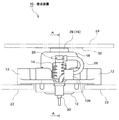
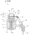
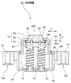
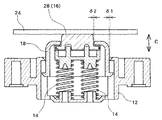
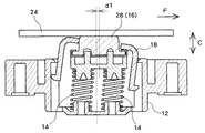
以下、本発明の好適な実施形態について図面を参照して説明する。図1は、本実施形態にかかる接点装置10の一例を示す外観図、図2は、図1のA−A断面図、図3は図2のB−B断面図である。
Preferred embodiments of the present invention will be described below with reference to the drawings. FIG. 1 is an external view showing an example of a
接点装置10は、基体部12、弾性部材14、接点部16、中間体18、および導線20を含み、第一の部品22(例えば、車両ウインドウアンテナ用の信号処理ユニット等)側と被当接体としての第二の部品24(例えば、車両ウインドウ等)側との間で導通路を形成するために用いられる。図1〜3の例では、第一の部品22の導体パターン(図示せず)、導線20、金属リード部26、当接部28、および第二の部品24の導体パターン30が、この順に電気的に接続されて導通路が形成される。
The
基体部12は、第一の部品22側に固定される。図1〜図3の例では、基体部12は、ボルト挿入穴12aに螺入されたタップスクリュー(図示せず)により、第一の部品22に固定される。なお、基体部12は、絶縁性部材(例えばナイロン樹脂)によって構成するのが好適である。
The
中間体18は、基体部12に設けられたガイド部にガイドされ、所定区間内で第二の部品24に対して接離自在である。図2および図3に示すように、この例では、基体部12には、ガイド部としてのガイド孔34が設けられている。ガイド孔34は、第二の部品24側に開口を有し、第一の部品22の設置面に対して略垂直となる方向(図3の矢印Cに沿う方向;以下、C方向または上下方向と記す)に伸びる有底孔として設けられている。また、断面は略長穴状である。中間体18は、このガイド孔34に案内され、基体部12の被当接体(第二の部品24)側の端面から出没自在となる。
The
また、この例では、ガイド孔34の口先(開口端)に、中間体18の脱落を防止する係合爪36が設けられている。また、中間体18の根元側にも係合爪38が設けられている。中間体18の最も上方の位置(上死点)はこれら係合爪36,38の係合によって定まる(図2、3に示される位置)。なお、中間体18の最も下方の位置(下死点)は、中間体18の底部がガイド孔34の底部に当接するまで没した位置または弾性部材14が最も短くなった位置となる。
In this example, an
また、中間体18は、ガイド孔34に緩装されている。すなわち、中間体18の外壁とガイド孔34の内壁との間には所定の間隙があり、この間隙の分、中間体18は、図3の矢印Dの方向(以下、D方向または横方向と記す)に移動自在である。さらに、この間隙は、中間体18がガイド孔34に挿入された状態で、接離方向(略C方向)に対して所定の角度範囲内で傾斜可能となるように設定されている。この間隙の構成および中間体18の傾斜の効果については後述する。
The
さらに、中間体18は、上底壁および側壁を有する筒状の部材として構成される。そして、上底壁に設けられた窓としての貫通孔40に当接部28が緩挿され、当接部28が第二の部品24側に露出している。この貫通孔40の側壁と当接部28の側壁とが係合することで、中間体18は、接点部16の横方向への動きに連動することになる。したがって、接点部16の横方向の可動範囲は、中間体18の可動範囲によって規制される。
Furthermore, the
また、当接部28の外壁と貫通孔40の内壁との間には所定の間隙があり、この間隙の分、当接部28は、貫通孔40の軸方向と垂直な方向(図3の姿勢ではD方向)に移動自在である。さらに、その間隙は、当接部28が貫通孔40内に挿入された状態で、貫通孔40の軸方向(図3の姿勢ではC方向)に対して所定の角度範囲内で傾斜可能となるように設定されている。この間隙の構成および当接部28の傾斜の効果についても後述する。
Further, there is a predetermined gap between the outer wall of the
接点部16は、弾性部材14により第二の部品24に向けて(すなわち上方向に)付勢され、当該第二の部品24に押しつけられる。この例では、接点部16は、当接部28、金属リード部26、および絶縁体32を含む。このうち当接部28は、上面側に、略平面状の当接面を有している。また当接部28は、底面側で横方向に張り出す鍔部16aを有している。鍔部16aの上面と中間体18の上底の下面とが係合することで、中間体18は、接点部16の上方向への動きに連動することになる。したがって、接点部16の上方向への可動範囲は、中間体18の可動範囲によって規制される。なお、通常、接点装置10は、多少傾斜する場合はあるが、基本的には第一の部品22側が鉛直下方側となる姿勢で装着されるため、中間体18は、作用する重力によって鍔部16a上に載置される。このため、中間体18は、接点部16の下方向への動きにも連動することになる。
The
さて、上述したように、この例では、金属リード部26および導線20を導通路として用い、金属導体からなる弾性部材(例えばコイルスプリング)14は導通路として用いないようにしている。これは、導通路として金属導体からなる弾性部材14(特にコイルスプリングの場合)を用いると、そのインダクタンスが、高周波信号の伝送特性に悪影響を及ぼすからである。そこで、この例では、絶縁体32を用いて、弾性部材14と導通路(この例では金属リード部26や当接部28)とを絶縁している。
As described above, in this example, the
また、導通路と弾性部材14との距離が近いと、金属リード部26、弾性部材14、およびグラウンド電極(図示せず)という経路で高周波信号が漏洩し、伝送特性に悪影響を及ぼす場合がある。そこで、この例では、高周波信号が使用周波数帯域において漏洩しないように、絶縁体32によって、導通路(この例では金属リード部26)と弾性部材14との距離を確保している。
If the distance between the conduction path and the
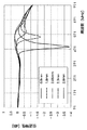
図4は、接点装置10の導通路を伝送される信号の周波数と信号強度との関係を、導通路と弾性部材14との距離(弾性部材14の上端と金属リード部26の下端との距離)毎に示す図である。この図4から、当該距離が短い場合には、特定の周波数帯域で信号強度が低下しているが、当該距離が長くなるにつれ、信号強度の落ち込みが少なくなり、伝送特性が改善していることがわかる。弾性部材14の上端と金属リード部26との間の距離は、金属リード部26の面積や形状、介在する部材等の比誘電率、使用する周波数帯域、周囲の金属物等の配置などを考慮して決める必要があり、この例の場合には、さらに、コイルスプリングの直径、線径、巻数、材質、長さ等を考慮して決める必要がある。
FIG. 4 shows the relationship between the frequency of the signal transmitted through the conduction path of the
また、この例では、図2および図3に示すように、絶縁体32にアーム32aを形成し、弾性部材14の上端と導通路下端(金属リード部26)との間に空隙42が形成されるようにしている。空気の比誘電率は絶縁体32の比誘電率より低いため、このような構成とすることで、導通路と弾性部材14との間の寄生キャパシタンスをさらに低くし、伝送特性をより一層向上することができる。なお、この例では、アーム32aによって空隙42を形成しているが、絶縁体32に空洞を設けることによっても同様の効果が期待できる。
In this example, as shown in FIGS. 2 and 3, an
さらに、この例では、図3に示すように、例えば金属板を成形して成る金属リード部26は、横方向外側(図2の矢印E方向)に向けて延伸するアーム26aを備えており、このアーム26aと導線20とが結線されている。接点部16に接続される導線20は、当該接点部16の上下動に伴って伸縮することになるが、このとき、弾性部材14側より内側の位置で導線20が接点部16に接続されていると、折れ曲がった導線20が弾性部材14に近づくことも考えられる。そこで、この例では、弾性部材14の側端に対して横方向外側となる位置で接点部16と導線20とを結線することで、導線20を弾性部材14から遠ざけ、寄生キャパシタンスが低く維持できるようにしている。また、基体部12に、導線20を係止する係止部12bを設け、この係止部12bによっても導線20の位置を規制するようにしている。こうすることで、接点部16に無理な力が加わってスムーズな上下動が妨げられるのを抑制している。
Furthermore, in this example, as shown in FIG. 3, for example, the
当接部28および金属リード部26は、絶縁体32のピン32bにより位置決めされた状態で載置されており、当接部28、金属リード部26および絶縁体32は、接点部16として、一体となって横方向および上方向に移動する。また、当接部28は、弾性部材14による上方向付勢力の反力により、その上面から第二の部品24または中間体18から下方向に押されるから、当接部28、金属リード部26および絶縁体32は、下方向にも一体となって移動する。
The
弾性部材14は、この例では、平行に配置された二つのコイルスプリングであり、図3の状態、すなわち、中間体18が最も上方の位置にある状態で、自由長より短くなるように構成されている。そして、接点部16が被当接体(第二の部品24)に当接した状態では、接点部16が下方に押し込まれ、コイルスプリングとしての弾性部材14が伸長する方向の付勢力を発生するように、基体部12下面と被当接体の当接面(導体パターン30の表面)との距離や、接点装置10の各部の寸法が決定される。この付勢力が、当接面における接触面圧の元となる。なお、弾性部材14として一つあるいは三つ以上のコイルスプリングを用いてもよいし、コイルスプリング以外の弾性部材(例えば板ばね等)を用いるようにしてもよい。なお、中間体18は、接点部16と係合するものの、この弾性部材14からの付勢力は作用しないように構成されている。
In this example, the
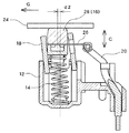
図5〜図7は、実装された状態(第一の部品22に取り付けられ、接点部16が被当接体としての第二の部品24の被当接面を押圧する状態)における接点装置10の内部部品の配置や姿勢を例示する図であり、図5は、被当接体から接点部16が横方向にオフセットすることなく比較的真っ直ぐ押し込まれた場合の図、図6は、接点部16が横方向(F方向)にオフセットして押し込まれた場合の図、また図7は、接点部16が横方向(G方向)にオフセットして押し込まれた場合の図である。
5 to 7 show the
図5のように、接点部16がほぼ直下方に押し下げられた場合には、中間体18はガイド孔34のガイド方向(C方向)に対して傾斜することなく、図3の姿勢からそのまま下方に移動することになる。図5からわかるように、この例では、接点部16と基体部12との間に中間体18を介在させているので、接点部16の上下方向(C方向)の可動範囲は、中間体18とガイド孔34との重なり合う部分の長さによって決まる。すなわち、接点部16の可動範囲に、中間体18の構造が関与している。従来のように、中間体18が無く、接点部16が直接ガイド孔34にガイドされる構成で接点部16の可動距離を長くしようとすると、接点部16自体を大きくしなければならない。これに対し、本実施形態のように、中間体18を設ければ、接点部16自体を大きくすることなく、接点部16の移動距離を長くすることができるようになる。かかる構造は、接点部16が特殊な材質であったり高価な材質であったりする場合や、弾性部材14のバネ定数などの観点から、接点部16を小型化したい場合に有効である。例えば、当接部28を導電性ゴムとする場合、その耐久性の観点から、当接部28はなるべく塊状に、かつ応力集中が生じにくい形状とするのが望ましい。かかる中間体18を介在させる構造は、当接部28(接点部16)の形状の自由度が高くなるから、当接部28として導電性ゴムを用いる場合にも好適となる。
As shown in FIG. 5, when the
なお、中間体18は、ガイド孔34との間隙δ1の分だけ、傾斜しない姿勢で横方向にオフセットすることができる。さらに、当接部28は、当該当接部28の側壁と中間体18の貫通孔40との側壁との間隙δ2の分だけ、同じく傾斜しない姿勢で横方向にオフセットすることができる。これは、この姿勢での接点部16の横方向の移動量が、それらの間隙δ1,δ2の大きさによって定まっていることを意味する。
Note that the
一方、図6のように、接点部16が横方向(F方向)にさらに大きくオフセットする場合には(オフセット量:d1)、中間体18はC方向に対して傾斜し、さらに、接点部16は中間体18に対して傾斜することになる。その結果、接点部16は、略平面状の当接面で被当接体に当接している状態を維持したまま、比較的(図5の場合より)長い距離を横方向に移動することができる。これは、上述したように、中間体18が接点部16と横方向に係合するよう構成するとともに、中間体18をガイド孔34に対して傾斜可能とし、さらに接点部16を中間体18に対して傾斜可能とすることで実現される。このような構成とすることで、当接部28の当接面と被当接体の当接面とが、面接触の状態を維持したまま従来より大きくオフセットすることができるようになり、耐摩耗性が向上するとともに、片当たりによる接触抵抗の増大を抑制することができる。
On the other hand, when the
さらに、中間体18のガイド部(ガイド孔34)に対する傾斜量(C方向に対する傾斜角)が大きくなるよう、ガイド孔34の側壁と中間体18の外壁との間の間隙を、第二の部品24側(上側)に向かうにつれて広くするのが好適である。この例では、中間体18を先細形状(テーパ状;上側に向かうほど細くなる形状)としている。ガイド方向に沿って当該間隙が一定であると、中間体18の第一の部品22側への押し込み量が大きくなるほど、中間体18の傾きが小さくなり、接点部16の横方向(F方向)のオフセット量が小さくなってしまう。本実施形態では、上記構成とすることで、中間体18が押し込まれた場合にも、中間体18の傾斜量を確保し、接点部16の横方向のオフセット量が大きくなるようにしている。
Further, the gap between the side wall of the
なお、本実施形態では、被当接体(第二の部品24)が、第一の部品22に対して平行となっていない場合にも、接点部16と被当接体との間で面接触が維持される。被当接体の傾きの許容範囲は、基体部12に対する中間体18の傾き量と、中間体18に対する接点部16の傾き量との合計として決定される。
In the present embodiment, even when the abutted body (second component 24) is not parallel to the
また、図7のように、接点部16が横方向(G方向)にさらに大きくオフセットする場合にも(オフセット量:d2)、中間体18はG方向に傾き、さらに、接点部16は中間体18に対して傾斜する。その結果、接点部16は、略平面状の当接面で被当接体に当接する状態を維持したまま、横方向に移動することができる。なお、G方向のオフセット量を大きくするためには、中間体18を先細形状(テーパ状;上側に向かうほど細くなる形状)とすることが望ましい。
Also, as shown in FIG. 7, when the
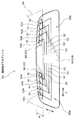
図8は、本実施形態にかかる接点装置10を用いた車両用ガラスアンテナ50の概略構成の一例を示す図である。車両用ガラスアンテナ50のアンテナエレメント52は、車両の例えばリアウインドウガラス54の車室側に、印刷等により貼り付けられている。各アンテナエレメント52の一端は、車両のルーフパネル56とリアウインドウガラス54の重合部分Hまで延びている。ルーフパネル56には、アンテナエレメント52で受信した信号を処理するためにアンプをはじめとする処理回路を支持した基板支持ベース58が、例えば、ボルト等で固定されている。なお、重合部分Hには、図示しないカバー等が取り付けられ外部からは見えないようになっている。
FIG. 8 is a diagram illustrating an example of a schematic configuration of the vehicle glass antenna 50 using the
基板支持ベース58には、アンプ等の処理回路やアンテナエレメント52の端部に形成された端部接点52aと接触する接点装置10が載置される。したがって、接点装置10とリアウインドウガラス54の端部接点52aとが押圧接触して、アンテナエレメント52と基板支持ベース58の内部回路との間の導通が確保されるように、基板支持ベース58は、ルーフパネル56に対して所定の位置に固定される。なお、図8では、ダイバシティが構成されるよう、実質的に同等の機能を備えるアンテナユニット50a,50bが二系統設けられている。また、アンテナエレメント52の本数や形状は、図示のものには限定されず、その機能等に応じて適宜設定される。なお、図8の例では、基板支持ベース58が上記第一の部品22に相当し、リアウインドウガラス54が上記第二の部品24、すなわち被当接体に相当し、端部接点52aが導体パターン30に相当する。
On the
さて、かかる構成の車両用ガラスアンテナ50では、まず、接点装置10の載置された基板支持ベース58がルーフパネル56上に取り付けられ、次に、リアウインドウガラス54が所定の位置に載置され、固定される。この作業において、取り付け位置の微調整のため、リアウインドウガラス54は、図8のI方向やJ方向などリアウインドウガラス54の面に沿った方向に動かされる場合が多い。ここで、被当接体としてのリアウインドウガラス54は、車両に装着された状態では、接点装置10の接点部16を所定量だけ押し込むことになるから、リアウインドウガラス54は、車両側の装着位置に到達する前に、必ず接点装置10に接触することになる。このため、リアウインドウガラス54は、接点装置10と端部接点52aが接触した状態で、当該方向(接点装置10にとっては横方向)に移動することになる。本実施形態にかかる接点装置10は、上述したように、接点部16(当接部28)と第二の部品24とが面接触した状態で横方向にずれる場合に、摩耗が少なく、かつ片当たりによる接触抵抗の増大が抑制されるから、こうした構成および組み付けが行われる車両用ガラスアンテナ50用の接点装置10としては極めて有効である。
In the vehicle glass antenna 50 having such a configuration, first, the
以上、本発明の好適な実施形態について説明したが、本発明は上記実施形態には限定されず、等価な範囲内で種々の変形が可能であることを理解されたい。 Although the preferred embodiments of the present invention have been described above, it should be understood that the present invention is not limited to the above-described embodiments, and various modifications can be made within an equivalent range.
10 接点装置、12 基体部、12a ボルト挿入穴、12b 係止部、14 弾性部材、16 接点部、16a 鍔部、18 中間体、20 導線、22 (第一の)部品、24 (第二の)部品(被当接体)、26 金属リード部、26a アーム、28 当接部、30 導体パターン、32 絶縁体、32a アーム、32b ピン、34 ガイド孔、36,38 係合爪、40 貫通孔、42 空隙、50 車両用ガラスアンテナ、50a,50b アンテナユニット、52 アンテナエレメント、52a 端部接点、54 リアウインドウガラス、56 ルーフパネル、58 基板支持ベース。
DESCRIPTION OF
Claims (8)
前記基体部に装着された弾性部材に付勢されて被当接体に押しつけられる接点部と、
前記基体部に設けられたガイド部にガイドされて所定区間内で被当接体に対して接離自在となる中間体であって、前記弾性部材に直接的に付勢されることなく、前記接点部と係合して当該接点部の可動範囲を規制する中間体と、
を備える接点装置。 A base part;
A contact portion that is urged by an elastic member attached to the base portion and pressed against the contacted body;
An intermediate body that is guided by a guide portion provided in the base portion and can be brought into and out of contact with a contacted body within a predetermined section, without being urged directly by the elastic member, An intermediate body that engages the contact portion and regulates the movable range of the contact portion;
A contact device comprising:
前記接点部の可動範囲が、当該接点部と前記窓との間隙および当該接点部と前記ガイド部との間隙によって規制されることを特徴とする請求項1〜4のうちいずれか一つに記載の接点装置。 The contact portion is loosely inserted in a window provided in the intermediate body,
The movable range of the contact portion is regulated by a gap between the contact portion and the window and a gap between the contact portion and the guide portion. Contact device.
前記基体部に装着された弾性部材によって、車両用ガラスに設けられたアンテナエレメントの被当接部に押しつけられる接点部と、
前記基体部に設けられたガイド部にガイドされて被当接体に対して所定区間内で接離自在となる中間体であって、前記接点部と係合して当該接点部の可動範囲を規制する中間体と、
を備える車両用ガラスアンテナに用いられる接点装置。 A base part;
A contact portion that is pressed against a contacted portion of an antenna element provided on the vehicle glass by an elastic member attached to the base portion;
An intermediate body that is guided by a guide portion provided on the base portion and can be brought into and out of contact with a contacted body within a predetermined section, and engages with the contact portion to thereby provide a movable range of the contact portion. Intermediates to regulate,
A contact device used for a vehicle glass antenna.
Priority Applications (1)
| Application Number | Priority Date | Filing Date | Title |
|---|---|---|---|
| JP2003400483A JP4194924B2 (en) | 2003-11-28 | 2003-11-28 | Contact device |
Applications Claiming Priority (1)
| Application Number | Priority Date | Filing Date | Title |
|---|---|---|---|
| JP2003400483A JP4194924B2 (en) | 2003-11-28 | 2003-11-28 | Contact device |
Publications (2)
| Publication Number | Publication Date |
|---|---|
| JP2005166312A true JP2005166312A (en) | 2005-06-23 |
| JP4194924B2 JP4194924B2 (en) | 2008-12-10 |
Family
ID=34724744
Family Applications (1)
| Application Number | Title | Priority Date | Filing Date |
|---|---|---|---|
| JP2003400483A Expired - Fee Related JP4194924B2 (en) | 2003-11-28 | 2003-11-28 | Contact device |
Country Status (1)
| Country | Link |
|---|---|
| JP (1) | JP4194924B2 (en) |
Cited By (5)
| Publication number | Priority date | Publication date | Assignee | Title |
|---|---|---|---|---|
| JP2008091297A (en) * | 2006-10-05 | 2008-04-17 | Kojima Press Co Ltd | Contact point device |
| JP2008546164A (en) * | 2005-06-10 | 2008-12-18 | デラウェア キャピタル フォーメーション インコーポレイテッド | Electrical contact probe with flexible internal interconnect |
| WO2013011985A1 (en) * | 2011-07-19 | 2013-01-24 | 日本発條株式会社 | Contact structure unit |
| JP2017183266A (en) * | 2016-03-29 | 2017-10-05 | 宏致電子股▲ふん▼有限公司Aces Electronics Co.,Ltd. | connector |
| CN108172712A (en) * | 2017-12-22 | 2018-06-15 | 斯坦德机器人(深圳)有限公司 | A kind of charging pile equipment with contraposition charging structure |
-
2003
- 2003-11-28 JP JP2003400483A patent/JP4194924B2/en not_active Expired - Fee Related
Cited By (8)
| Publication number | Priority date | Publication date | Assignee | Title |
|---|---|---|---|---|
| JP2008546164A (en) * | 2005-06-10 | 2008-12-18 | デラウェア キャピタル フォーメーション インコーポレイテッド | Electrical contact probe with flexible internal interconnect |
| JP2008091297A (en) * | 2006-10-05 | 2008-04-17 | Kojima Press Co Ltd | Contact point device |
| WO2013011985A1 (en) * | 2011-07-19 | 2013-01-24 | 日本発條株式会社 | Contact structure unit |
| JPWO2013011985A1 (en) * | 2011-07-19 | 2015-02-23 | 日本発條株式会社 | Contact structure unit |
| US9373900B2 (en) | 2011-07-19 | 2016-06-21 | Nhk Spring Co., Ltd. | Contact structure unit |
| JP2017183266A (en) * | 2016-03-29 | 2017-10-05 | 宏致電子股▲ふん▼有限公司Aces Electronics Co.,Ltd. | connector |
| CN108172712A (en) * | 2017-12-22 | 2018-06-15 | 斯坦德机器人(深圳)有限公司 | A kind of charging pile equipment with contraposition charging structure |
| CN108172712B (en) * | 2017-12-22 | 2024-02-06 | 斯坦德机器人(深圳)有限公司 | Fill electric pile equipment with counterpoint charging structure |
Also Published As
| Publication number | Publication date |
|---|---|
| JP4194924B2 (en) | 2008-12-10 |
Similar Documents
| Publication | Publication Date | Title |
|---|---|---|
| JP4194923B2 (en) | Contact device | |
| TWI761862B (en) | Coaxial connector with floating mechanism | |
| US9620900B2 (en) | Coaxial connector with floating mechanism | |
| US6821131B2 (en) | IC socket for a fine pitch IC package | |
| US11552421B2 (en) | Electrical connector with floating contacts each with multiple impedances | |
| US10559921B2 (en) | Connector | |
| KR20150080486A (en) | Contact element for transmitting high-frequency signals between two circuit boards | |
| JP2005512289A (en) | Electrical connector | |
| US9472867B2 (en) | Electric contact and electric component socket | |
| JP2007501498A (en) | connector | |
| US20050001822A1 (en) | Resilient switch contact for a key switch device | |
| JP4194924B2 (en) | Contact device | |
| US11476069B2 (en) | Low noise relay | |
| JP2005332644A (en) | Contact device | |
| US8242773B2 (en) | Vehicle switch | |
| JP4361831B2 (en) | Contact device | |
| JP2005166307A (en) | Contact device and its contacting member | |
| JP3611754B2 (en) | Antenna structure | |
| JP5227124B2 (en) | Contact device | |
| JP2004265598A (en) | connector | |
| JP4279860B2 (en) | Vehicle antenna connection device | |
| US20200343672A1 (en) | Electrical connector and locking member | |
| KR101546833B1 (en) | sensor module with contact spring | |
| KR101546840B1 (en) | sensor module with contact spring | |
| KR101640601B1 (en) | Relay connector |
Legal Events
| Date | Code | Title | Description |
|---|---|---|---|
| A621 | Written request for application examination |
Free format text: JAPANESE INTERMEDIATE CODE: A621 Effective date: 20060616 |
|
| A977 | Report on retrieval |
Free format text: JAPANESE INTERMEDIATE CODE: A971007 Effective date: 20080605 |
|
| A131 | Notification of reasons for refusal |
Free format text: JAPANESE INTERMEDIATE CODE: A131 Effective date: 20080617 |
|
| A521 | Written amendment |
Free format text: JAPANESE INTERMEDIATE CODE: A523 Effective date: 20080812 |
|
| TRDD | Decision of grant or rejection written | ||
| A01 | Written decision to grant a patent or to grant a registration (utility model) |
Free format text: JAPANESE INTERMEDIATE CODE: A01 Effective date: 20080909 |
|
| A01 | Written decision to grant a patent or to grant a registration (utility model) |
Free format text: JAPANESE INTERMEDIATE CODE: A01 |
|
| A61 | First payment of annual fees (during grant procedure) |
Free format text: JAPANESE INTERMEDIATE CODE: A61 Effective date: 20080924 |
|
| R150 | Certificate of patent or registration of utility model |
Ref document number: 4194924 Country of ref document: JP Free format text: JAPANESE INTERMEDIATE CODE: R150 Free format text: JAPANESE INTERMEDIATE CODE: R150 |
|
| FPAY | Renewal fee payment (event date is renewal date of database) |
Free format text: PAYMENT UNTIL: 20111003 Year of fee payment: 3 |
|
| FPAY | Renewal fee payment (event date is renewal date of database) |
Free format text: PAYMENT UNTIL: 20111003 Year of fee payment: 3 |
|
| FPAY | Renewal fee payment (event date is renewal date of database) |
Free format text: PAYMENT UNTIL: 20121003 Year of fee payment: 4 |
|
| R250 | Receipt of annual fees |
Free format text: JAPANESE INTERMEDIATE CODE: R250 |
|
| FPAY | Renewal fee payment (event date is renewal date of database) |
Free format text: PAYMENT UNTIL: 20131003 Year of fee payment: 5 |
|
| R250 | Receipt of annual fees |
Free format text: JAPANESE INTERMEDIATE CODE: R250 |
|
| R250 | Receipt of annual fees |
Free format text: JAPANESE INTERMEDIATE CODE: R250 |
|
| R250 | Receipt of annual fees |
Free format text: JAPANESE INTERMEDIATE CODE: R250 |
|
| R250 | Receipt of annual fees |
Free format text: JAPANESE INTERMEDIATE CODE: R250 |
|
| R250 | Receipt of annual fees |
Free format text: JAPANESE INTERMEDIATE CODE: R250 |
|
| R250 | Receipt of annual fees |
Free format text: JAPANESE INTERMEDIATE CODE: R250 |
|
| R250 | Receipt of annual fees |
Free format text: JAPANESE INTERMEDIATE CODE: R250 |
|
| R250 | Receipt of annual fees |
Free format text: JAPANESE INTERMEDIATE CODE: R250 |
|
| LAPS | Cancellation because of no payment of annual fees |