JP2005158181A - Disc player and electronic device - Google Patents
Disc player and electronic device Download PDFInfo
- Publication number
- JP2005158181A JP2005158181A JP2003397432A JP2003397432A JP2005158181A JP 2005158181 A JP2005158181 A JP 2005158181A JP 2003397432 A JP2003397432 A JP 2003397432A JP 2003397432 A JP2003397432 A JP 2003397432A JP 2005158181 A JP2005158181 A JP 2005158181A
- Authority
- JP
- Japan
- Prior art keywords
- surface portion
- light
- lens
- pair
- horizontally long
- Prior art date
- Legal status (The legal status is an assumption and is not a legal conclusion. Google has not performed a legal analysis and makes no representation as to the accuracy of the status listed.)
- Granted
Links
Images
Classifications
-
- G—PHYSICS
- G02—OPTICS
- G02B—OPTICAL ELEMENTS, SYSTEMS OR APPARATUS
- G02B6/00—Light guides; Structural details of arrangements comprising light guides and other optical elements, e.g. couplings
- G02B6/0001—Light guides; Structural details of arrangements comprising light guides and other optical elements, e.g. couplings specially adapted for lighting devices or systems
- G02B6/0011—Light guides; Structural details of arrangements comprising light guides and other optical elements, e.g. couplings specially adapted for lighting devices or systems the light guides being planar or of plate-like form
- G02B6/0013—Means for improving the coupling-in of light from the light source into the light guide
- G02B6/0015—Means for improving the coupling-in of light from the light source into the light guide provided on the surface of the light guide or in the bulk of it
- G02B6/0018—Redirecting means on the surface of the light guide
-
- G—PHYSICS
- G02—OPTICS
- G02B—OPTICAL ELEMENTS, SYSTEMS OR APPARATUS
- G02B6/00—Light guides; Structural details of arrangements comprising light guides and other optical elements, e.g. couplings
- G02B6/0001—Light guides; Structural details of arrangements comprising light guides and other optical elements, e.g. couplings specially adapted for lighting devices or systems
- G02B6/0011—Light guides; Structural details of arrangements comprising light guides and other optical elements, e.g. couplings specially adapted for lighting devices or systems the light guides being planar or of plate-like form
- G02B6/0013—Means for improving the coupling-in of light from the light source into the light guide
- G02B6/0015—Means for improving the coupling-in of light from the light source into the light guide provided on the surface of the light guide or in the bulk of it
- G02B6/002—Means for improving the coupling-in of light from the light source into the light guide provided on the surface of the light guide or in the bulk of it by shaping at least a portion of the light guide, e.g. with collimating, focussing or diverging surfaces
-
- G—PHYSICS
- G11—INFORMATION STORAGE
- G11B—INFORMATION STORAGE BASED ON RELATIVE MOVEMENT BETWEEN RECORD CARRIER AND TRANSDUCER
- G11B33/00—Constructional parts, details or accessories not provided for in the other groups of this subclass
- G11B33/02—Cabinets; Cases; Stands; Disposition of apparatus therein or thereon
- G11B33/027—Covers
-
- G—PHYSICS
- G11—INFORMATION STORAGE
- G11B—INFORMATION STORAGE BASED ON RELATIVE MOVEMENT BETWEEN RECORD CARRIER AND TRANSDUCER
- G11B33/00—Constructional parts, details or accessories not provided for in the other groups of this subclass
- G11B33/10—Indicating arrangements; Warning arrangements
Landscapes
- Physics & Mathematics (AREA)
- General Physics & Mathematics (AREA)
- Optics & Photonics (AREA)
- Illuminated Signs And Luminous Advertising (AREA)
- Led Device Packages (AREA)
- Optical Elements Other Than Lenses (AREA)
Abstract
【課題】1つの光源によってレンズの横長形状の発光面の全体を発光させることが可能なディスクプレーヤおよび電子機器を提供する。
【解決手段】平板状のアクリルレンズ70と、青色発光ダイオード81とを備えたディスクプレーヤ1において、アクリルレンズ70は、1つの青色発光ダイオード81からの光が入射する底面部71と、入射した光を出射する横長形状の前面部73と、前面部73および底面部71に対して所定の鋭角度で傾斜し、底面部71からの光を前面部73の方向に反射する互いに対向する一対の側面部74と、一対の側面部74の端部を連結するように設けられ、底面部71に対して実質的に直交する背面部75とを含む。また、側面部74は、背面部75に向かうに従って、底面部71に対する傾斜角度が徐々に直角に近づくように形成されている。
【選択図】図10
A disc player and an electronic apparatus are provided that can emit light from the entire light emitting surface of a lens with a single light source.
In a disc player having a flat acrylic lens and a blue light-emitting diode, the acrylic lens has a bottom surface portion on which light from one blue light-emitting diode is incident, and incident light. A pair of side surfaces facing each other that are inclined at a predetermined acute angle with respect to the front surface portion 73 and the bottom surface portion 71 and reflect light from the bottom surface portion 71 toward the front surface portion 73. Part 74 and a back part 75 that is provided so as to connect the ends of the pair of side parts 74 and substantially orthogonal to bottom part 71. Further, the side surface portion 74 is formed so that the inclination angle with respect to the bottom surface portion 71 gradually approaches a right angle toward the back surface portion 75.
[Selection] Figure 10
Description
本発明は、ディスクプレーヤおよび電子機器に関し、特に、光源からの光を出射するレンズを備えたディスクプレーヤおよび電子機器に関する。 The present invention relates to a disc player and an electronic device, and more particularly to a disc player and an electronic device including a lens that emits light from a light source.
従来、光源からの入射光を拡散させて出射するレンズ(導光板)およびそのレンズを備えた電子機器が知られている(たとえば、特許文献1および特許文献2参照)。 Conventionally, a lens (light guide plate) that diffuses and emits incident light from a light source and an electronic device including the lens are known (see, for example, Patent Document 1 and Patent Document 2).
上記特許文献1には、1つのLED(発光ダイオード)からの光を側面から導光して、平面的に見て矩形形状の発光面から出射するための導光板(レンズ)を備えた従来の面発光装置が開示されている。 Patent Document 1 discloses a conventional light guide plate (lens) that guides light from one LED (light emitting diode) from a side surface and emits the light from a light emitting surface having a rectangular shape when seen in a plan view. A surface emitting device is disclosed.
また、上記特許文献2には、長方形状の線状発光体の一方の側面近傍に1つの光源(LED)を配置して、その光源からの光を線状の発光面から出射させる構造が開示されている。また、上記特許文献2には、円弧状の発光面を有する扇形状の導光板と、その導光板の円弧中心側の側面に円弧状の発光面に発光方向を向けて配置された1つの光源(LED)とからなる組を複数組み合わせて円環状の発光を得る構造も開示されている。 Patent Document 2 discloses a structure in which one light source (LED) is arranged near one side surface of a rectangular linear light emitter, and light from the light source is emitted from the linear light emitting surface. Has been. In Patent Document 2, a fan-shaped light guide plate having an arcuate light emitting surface, and one light source arranged on the side surface on the arc center side of the light guide plate with the light emitting direction facing the arcuate light emitting surface. A structure for obtaining annular light emission by combining a plurality of sets of (LED) is also disclosed.
ところで、従来、2つの光源からの光により発光する横長のアクリルレンズを備えたディスクプレーヤ(電子機器)が知られている。 By the way, a disk player (electronic device) having a horizontally long acrylic lens that emits light by light from two light sources is known.
図11は、従来のディスクプレーヤを部分的に示した図である。図12は、図11に示した従来のディスクプレーヤにおけるアクリルレンズを示した上面図である。図13は、図12に示したアクリルレンズの前面図である。図11〜図13を参照して、従来のディスクプレーヤ100の構造について説明する。
FIG. 11 is a diagram partially showing a conventional disc player. FIG. 12 is a top view showing an acrylic lens in the conventional disc player shown in FIG. FIG. 13 is a front view of the acrylic lens shown in FIG. The structure of a
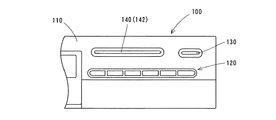
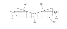
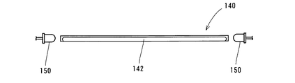
従来のディスクプレーヤ100は、図11に示すように、ディスクプレーヤ100の前面を覆うフロントパネル110と、フロントパネル110に設けられた操作ボタン120と、録画ボタン130と、平板状のアクリルレンズ140とを備えている。また、図12および図13に示すように、アクリルレンズ140の左右の両端部からほぼ同じ距離だけ離れた位置には、光源となる2つの発光ダイオード150が配置されている。アクリルレンズ140は、フロントパネル110の内面から前面に露出するようにディスクプレーヤ100の内部に取り付けられている。このアクリルレンズ140は、録画ボタン130の操作によってディスクプレーヤ100が録画状態にあることをユーザに知らせるために設けられている。また、平板状のアクリルレンズ140は、図12および図13に示すように、入射光を反射する一対の背面部141と、反射した光を出射することにより発光する横長形状の前面部142とを含んでいる。一対の背面部141は、互いに対向するように前面部142に対してV字状に形成されている。
As shown in FIG. 11, the
次に、従来のディスクプレーヤ100のアクリルレンズ140による光の反射の機構について説明する。2つの発光ダイオード150によって、アクリルレンズ140の左右の両端部から、光がアクリルレンズ140に入射される。入射された光は、図12に示すように、一対の背面部141によって前面部142の方向に反射され、横長形状の前面部142から出射される。
図11〜図13に示した横長のアクリルレンズ140の前面部142を発光させるには、従来、横長形状の前面部142の全体を均一に発光させるために、アクリルレンズ140の側方に2つの発光ダイオード150を配置する必要があり、その結果、部品点数が増加するという問題点があった。
In order to cause the
また、上記特許文献1に開示された構造は、面状の発光を得るための構造であるので、特許文献1の構造では、横長形状の線状の発光を得るのは困難である。 Moreover, since the structure disclosed in Patent Document 1 is a structure for obtaining planar light emission, it is difficult for the structure of Patent Document 1 to obtain horizontally elongated light emission.
また、上記特許文献2に開示された長方形状の線状発光体の一方の側面近傍に1つの光源を配置して、その光源からの光を線状の発光面から出射させる構造では、線状の発光面の長さが長い横長形状になると、光源からの光が光源とは反対側の端部に届かなくなる。その結果、特許文献2の構造では、1つの光源(LED)を用いて横長形状の発光面を均一に発光させるのは困難であるという問題点がある。また、上記特許文献2に開示された円弧状の発光面を有する構造においても、1つのLEDが発光方向を円弧状の発光面に向けて配置されているため、LEDの指向性から一定以上の広がり角度の円弧状の発光面を発光させるのは困難であり、その結果、横方向に長い発光面を均一に発光させるのは困難であるという問題点がある。 Further, in the structure in which one light source is arranged near one side surface of the rectangular linear light emitter disclosed in Patent Document 2 above, the light from the light source is emitted from the linear light emitting surface. If the light emitting surface has a horizontally long shape, the light from the light source does not reach the end opposite to the light source. As a result, the structure of Patent Document 2 has a problem that it is difficult to uniformly emit light from a horizontally long light emitting surface using one light source (LED). Further, in the structure having the arc-shaped light emitting surface disclosed in Patent Document 2, since one LED is disposed with the light emitting direction directed toward the arc-shaped light emitting surface, the LED directivity exceeds a certain level. There is a problem that it is difficult to emit light from an arcuate light emitting surface having a spreading angle, and as a result, it is difficult to emit light uniformly from a light emitting surface that is long in the lateral direction.
この発明は、上記のような課題を解決するためになされたものであり、この発明の1つの目的は、1つの光源(発光ダイオード)によって横長形状の発光面の全体を発光させることが可能なディスクプレーヤおよび電子機器を提供することである。 The present invention has been made to solve the above-described problems, and one object of the present invention is to allow the entire light emitting surface having a horizontally long shape to emit light by one light source (light emitting diode). To provide a disc player and electronic equipment.
この発明の第1の局面によるディスクプレーヤは、機器の前面を覆うとともに、所定の位置に横長のパネル側貫通孔を含む樹脂製のフロントパネルと、フロントパネルの内面側に設けられ、フロントパネルの横長のパネル側貫通孔に嵌め込まれるとともに、所定の位置に横長のレンズ用貫通孔を有する樹脂製のレンズホルダと、レンズホルダの横長のレンズ用貫通孔に嵌め込まれるとともに、レンズホルダに固定されるアクリル製の平板状のレンズと、機器の内部に設けられた基板に取り付けられた発光ダイオードとを備えたディスクプレーヤにおいて、アクリル製の平板状のレンズは、平面的に見て実質的に台形状を有しており、かつ、発光ダイオードからの光が入射する底面部と、表面に光を反射させるための白色の印刷を施した上面部と、レンズホルダの横長のレンズ用貫通孔から前面に露出するように配置されるとともに、前方に向けて光を出射する横長形状の直線状の前面部と、前面部に対して平面的に所定の鋭角度で傾斜するとともに、底面部に対して所定の鋭角度で傾斜し、かつ、表面に微細な凹凸が形成され、底面部からの光を前面部の方向に反射する互いに対向する一対の側面部と、一対の側面部の端部を連結するように設けられ、底面部に対して実質的に直交するとともに、表面に微細な凹凸が形成された背面部とを含み、一対の側面部は、背面部に向かうに従って、底面部に対する傾斜角度が徐々に直角に近づくように形成され、発光ダイオードは、レンズの底面部の下方の所定の位置に上向きに1つ配置されるように構成されている。 A disc player according to a first aspect of the present invention is provided on a resin front panel that covers a front surface of a device and includes a horizontally long panel side through hole at a predetermined position, and an inner surface side of the front panel. A resin lens holder having a horizontally long lens through hole at a predetermined position, and a horizontally long lens through hole of the lens holder and being fixed to the lens holder. In a disc player comprising an acrylic flat lens and a light emitting diode mounted on a substrate provided inside the device, the acrylic flat lens is substantially trapezoidal when viewed in plan. And a bottom surface portion on which light from the light emitting diode is incident and a top surface portion on which white printing is performed to reflect the light on the surface The lens holder is disposed so as to be exposed to the front surface from the horizontally long lens through-hole, and has a horizontally long linear front surface portion that emits light toward the front, and has a predetermined planar shape with respect to the front surface portion. A pair of opposite side surfaces that are inclined at an acute angle, inclined at a predetermined acute angle with respect to the bottom surface portion, and have fine irregularities formed on the surface, and reflect light from the bottom surface portion toward the front surface portion. A pair of side portions, and a back surface portion that is substantially orthogonal to the bottom surface portion and has fine irregularities formed on the surface. The angle of inclination with respect to the bottom surface portion gradually approaches a right angle as it goes to the back surface portion, and one light emitting diode is arranged upward at a predetermined position below the bottom surface portion of the lens. Yes.
この第1の局面によるディスクプレーヤでは、上記のように、互いに対向する一対の側面部を前面部に対して平面的に所定の鋭角度で傾斜するとともに、底面部に対して所定の鋭角度で傾斜するように形成し、レンズの底面部の下方の所定の位置に上向きに1つの発光ダイオードを配置することによって、底面部から入射した光を一対の側面部において前面部の方向に反射させることができるので、底面部から入射した光を前面部から効率良く出射させることができる。これによって、光を底面部から入射させれば、発光面である直線状の横長形状の前面部を効率良く発光させることができるので、1つの発光ダイオード
によって横長形状の前面部の全体を効率良く発光させることができる。また、平板状のレンズの上面部の表面に白色の印刷を施すことによって、上面部の表面に白色の印刷を施さない場合に比べて、底面部から入射した光を上面部において前面部の方向に効率良く反射させることができるので、底面部から入射した光を横長形状の前面部の全体からより効率良く出射させることができる。また、背面部を底面部に対して実質的に直交するように形成することによって、底面部から入射した光が背面部において前面部の方向に反射するのを抑制することができる。これによって、レンズ内で反射した光がレンズの横長形状の前面部の中央近傍に集まり過ぎて、発光ダイオードの形状が前面部の中央近傍に映るのを防ぐことができるので、レンズの前面部から出射する光が一部分に偏るのを防止することができる。また、レンズの一対の側面部および背面部の表面に微細な凹凸を形成することによって、底面部から入射した光を一対の側面部および背面部で反射する際に、拡散させることができるので、レンズの横長形状の前面部から出射する光を均一にすることができる。
In the disc player according to the first aspect, as described above, the pair of side surface portions facing each other are inclined with respect to the front surface portion in a plane at a predetermined acute angle, and at a predetermined acute angle with respect to the bottom surface portion. By forming one light-emitting diode upward at a predetermined position below the bottom surface portion of the lens, the light incident from the bottom surface portion is reflected in the direction of the front surface portion at the pair of side surface portions. Therefore, light incident from the bottom surface can be efficiently emitted from the front surface. Thus, if light is incident from the bottom surface portion, the light emitting surface can be made to emit light efficiently in the straight horizontally long front portion, so that the entire horizontally long front portion can be efficiently formed by one light emitting diode. Can emit light. Also, by applying white printing on the surface of the upper surface portion of the flat lens, the light incident from the bottom surface portion is directed toward the front surface portion on the upper surface portion as compared with the case where white printing is not performed on the surface of the upper surface portion. Therefore, the light incident from the bottom surface can be more efficiently emitted from the entire horizontally long front surface. Moreover, it can suppress that the light which injected from the bottom face part reflects in the direction of the front part in a back face part by forming a back part so that it may cross substantially orthogonally with respect to a bottom face part. As a result, it is possible to prevent light reflected in the lens from gathering too near the center of the horizontally long front part of the lens and reflecting the shape of the light emitting diode near the center of the front part. It is possible to prevent the emitted light from being partially biased. In addition, by forming fine irregularities on the surface of the pair of side surface portions and the back surface portion of the lens, the light incident from the bottom surface portion can be diffused when reflected by the pair of side surface portions and the back surface portion. The light emitted from the horizontally long front surface portion of the lens can be made uniform.
この発明の第2の局面による電子機器は、光源と、光源からの光が入射する底面部と、光を出射する横長形状の前面部と、前面部に対して平面的に所定の鋭角度で傾斜するとともに、底面部に対して所定の鋭角度で傾斜し、かつ、底面部からの光を前面部の方向に反射する互いに対向する一対の側面部とを含む平板状のレンズとを備える。 An electronic apparatus according to a second aspect of the present invention includes a light source, a bottom surface portion on which light from the light source is incident, a horizontally long front surface portion that emits light, and a predetermined acute angle in plan with respect to the front surface portion. And a flat lens including a pair of side surfaces facing each other that are inclined at a predetermined acute angle with respect to the bottom surface and reflect light from the bottom surface toward the front surface.
この第2の局面による電子機器では、上記のように、互いに対向する一対の側面部を、前面部に対して平面的に所定の鋭角度で傾斜するとともに、底面部に対して所定の鋭角度で傾斜するように形成することによって、底面部から入射した光を一対の側面部において横長形状の前面部の方向に反射させることができるので、底面部から入射した光を発光面である横長形状の前面部から効率良く出射させることができる。これによって、光を底面部から入射させれば、横長形状の前面部を効率良く発光させることができるので、1つの光源によって横長形状の前面部の全体を効率良く発光させることができる。 In the electronic device according to the second aspect, as described above, the pair of side surface portions facing each other are inclined with respect to the front surface portion at a predetermined acute angle in a plane, and the predetermined acute angle with respect to the bottom surface portion. Since the light incident from the bottom surface portion can be reflected in the direction of the horizontally long front surface portion at the pair of side surface portions, the light incident from the bottom surface portion is the light emitting surface. It can be made to emit efficiently from the front part. Accordingly, if light is incident from the bottom surface portion, the horizontally long front portion can be efficiently emitted, so that the entire horizontally long front portion can be efficiently emitted by one light source.
上記第2の局面による電子機器において、好ましくは、平板状のレンズは、表面に光を反射させるための印刷を施した上面部をさらに含んでいる。このように構成すれば、上面部の表面に光を反射させるための印刷を施さない場合に比べて、底面部から入射した光を上面部において前面部の方向に効率良く反射させることができるので、底面部から入射した光を前面部の全体からより効率良く出射させることができる。 In the electronic device according to the second aspect, the flat lens preferably further includes an upper surface portion on which printing for reflecting light is performed. With this configuration, light incident from the bottom surface can be efficiently reflected in the direction of the front surface at the top surface compared to the case where printing for reflecting light is not performed on the surface of the top surface. In addition, light incident from the bottom surface can be more efficiently emitted from the entire front surface.
上記第2の局面による電子機器において、好ましくは、平板状のレンズは、一対の側面部の端部を連結するように設けられ、底面部に対して実質的に直交する背面部をさらに含み、一対の側面部は、背面部に向かうに従って、底面部に対する傾斜角度が徐々に直角に近づくように形成されている。このように構成すれば、底面部から入射した光が背面部において前面部の方向に反射するのを抑制することができる。これによって、レンズ内で反射した光がレンズの前面部の中央近傍に集まり過ぎて、光源の形状が前面部に映るのを防ぐことができるので、レンズの前面部から出射する光が一部分に偏るのを防止することができる。 In the electronic device according to the second aspect, preferably, the flat lens further includes a back surface portion provided so as to connect the end portions of the pair of side surface portions and substantially orthogonal to the bottom surface portion, The pair of side surface portions are formed such that the inclination angle with respect to the bottom surface portion gradually approaches a right angle toward the back surface portion. If comprised in this way, it can suppress that the light which injected from the bottom face part reflects in the direction of the front part in a back part. This prevents light reflected in the lens from gathering too close to the center of the front part of the lens and reflecting the shape of the light source on the front part, so that the light emitted from the front part of the lens is partially biased. Can be prevented.
この場合、好ましくは、一対の側面部および背面部の少なくとも一方は、表面に微細な凹凸が形成されている。このように構成すれば、底面部から入射した光を一対の側面部および背面部で反射する際に、拡散させることができるので、レンズの前面部から出射する光を均一にすることができる。 In this case, preferably, at least one of the pair of side surface portions and the back surface portion has fine irregularities formed on the surface. If comprised in this way, when the light which injected from the bottom face part is reflected in a pair of side part and back part, it can be diffused, Therefore The light radiate | emitted from the front part of a lens can be made uniform.
以下、本発明の実施の形態を図面に基づいて説明する。 Hereinafter, embodiments of the present invention will be described with reference to the drawings.
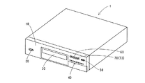
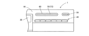
図1は、本発明の一実施形態によるディスクプレーヤを示した斜視図である。図2〜図4は、図1に示したディスクプレーヤの構造を部分的に示した図である。図5〜図9は、図1に示した本発明の一実施形態によるディスクプレーヤにおけるアクリルレンズの構造を示した図である。図1〜図9を参照して、本発明の一実施形態によるディスクプレーヤ1の構造について説明する。 FIG. 1 is a perspective view showing a disc player according to an embodiment of the present invention. 2 to 4 are diagrams partially showing the structure of the disc player shown in FIG. 5 to 9 are views showing the structure of the acrylic lens in the disc player according to the embodiment of the present invention shown in FIG. A structure of a disc player 1 according to an embodiment of the present invention will be described with reference to FIGS.
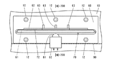
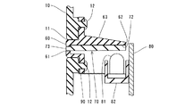
本発明の一実施形態によるディスクプレーヤ1は、図1および図2に示すように、樹脂製のフロントパネル10と、電源ボタン20と、ディスク挿入口30と、操作ボタン40と、録画ボタン50と、樹脂製のレンズホルダ60と、平板状のアクリルレンズ70とを備えている。このアクリルレンズ70は、録画ボタン50の操作によってディスクプレーヤ1が録画状態にあることをユーザに知らせるために設けられている。なお、ディスクプレーヤ1は、本発明の「電子機器」の一例であり、アクリルレンズ70は、本発明の「レンズ」の一例である。フロントパネル10は、図3および図4に示すように、横長のパネル側貫通孔11と、複数のボス部12とを含んでいる。また、樹脂製のレンズホルダ60は、横長の直線状のレンズ用貫通孔61と、張出部62と、3つの補強リブ63とを含んでいる。レンズホルダ60は、図4に示すように、横長の直線状のパネル側貫通孔11に嵌め込まれるとともに、樹脂製のフロントパネル10に一体的に形成された複数のボス部12によってフロントパネル10に固定されている。張出部62は、アクリルレンズ70を固定および支持するために設けられているとともに、遮光材としての機能も有する。
As shown in FIGS. 1 and 2, the disc player 1 according to an embodiment of the present invention includes a
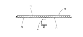
ここで、本実施形態では、ディスクプレーヤ1は、図4に示すように、内部に基板80を備えている。この基板80には、1つの青色発光ダイオード81がダイオードホルダ82によって取り付けられている。なお、青色発光ダイオード81は、本発明の「発光ダイオード」および「光源」の一例である。この1つの青色発光ダイオード81は、図3および図4に示すように、アクリルレンズ70の下方の所定の位置に上向きに配置されている。また、1つの青色発光ダイオード81の周囲には、図3および図4に示すように、ポリエステル製の遮光シート90が設けられている。この遮光シート90は、青色発光ダイオード81の光がアクリルレンズ70以外の部分からフロントパネル10の前面に漏れ出すのを防ぐために設けられている。
Here, in the present embodiment, the disc player 1 includes a
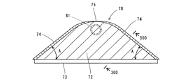
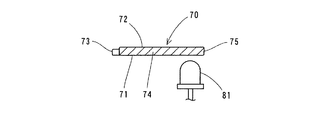
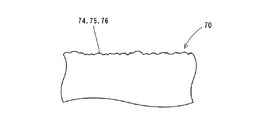
また、本実施形態では、平板状のアクリルレンズ70は、図5〜図8に示すように、底面部71と、上面部72と、横長形状の直線状の前面部73と、一対の側面部74と、背面部75とを含んでいる。底面部71は、青色発光ダイオード81からの光が入射する面である。上面部72の表面には、図5に示すように、光を反射させるために白色の印刷が施されている。横長形状の前面部73は、図4に示すように、レンズホルダ60の横長のレンズ用貫通孔61からフロントパネル10の前面に露出するように配置されている。この横長形状の直線状の前面部73は、アクリルレンズ70の内部に進入した光が出射する面である。また、前面部73には、図9に示すように、シボ加工などの多数の微細な凹凸が形成されている。この微細な凹凸は、前面部73より光が出射する際に、その出射光を散乱させるために設けられている。
In the present embodiment, as shown in FIGS. 5 to 8, the flat
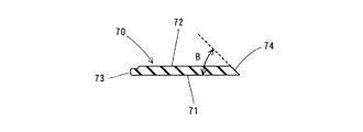
また、本実施形態では、一対の側面部74は、図5に示すように、前面部73に対して平面的に所定の角度A(本実施形態では、約30度)で傾斜するとともに、図8に示すように、底面部71に対して所定の角度B(本実施形態では、約45度)で傾斜するように構成されている。また、一対の側面部74の表面には、図9に示すように、シボ加工などの多数の微細な凹凸が形成されている。背面部75は、一対の側面部74の端部を連結するように設けられるとともに、底面部71に対して直交するように構成されている。また、背面部75の表面にも、図9に示すように、シボ加工などの多数の微細な凹凸が形成されている。一対の側面部74および背面部75の表面の微細な凹凸は、一対の側面部74および背面部75で光が反射する際に、光を乱反射させて散乱させるために設けられてい
る。また、一対の側面部74は、図5に示すように、背面部75に向かうに従って、底面部71に対する傾斜角度(本実施形態では、約45度)が徐々に直角に近づくように形成されている。また、図3および図4に示すように、平板状のアクリルレンズ70の上面部と樹脂製のレンズホルダ60の張出部62の下面とは、両面テープ(図示せず)によって固定されている。
In the present embodiment, as shown in FIG. 5, the pair of
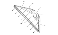
図10は、図5に示したアクリルレンズの側面部における入射光の反射の軌跡を示した斜視図である。次に、図10を参照して、本発明の一実施形態によるディスクプレーヤ1のアクリルレンズ70の一対の側面部74における入射光の反射の軌跡について説明する。まず、青色発光ダイオード81によって、アクリルレンズ70の底面部71から、光がアクリルレンズ70に入射される。入射された光は、図10に示すように、放射状に広がり、アクリルレンズ70の一対の側面部74の全面に到達する。この場合、一対の側面部74は、前面部73に対して平面的に約30度で傾斜する(図5参照)とともに、底面部71に対して約45度で傾斜する(図8参照)ように形成されている。このため、底面部71から入射した光は、一対の側面部74によって、アクリルレンズ70の横長形状の前面部73の方向に反射される。
FIG. 10 is a perspective view showing the locus of reflection of incident light on the side surface of the acrylic lens shown in FIG. Next, the locus of reflection of incident light on the pair of side surfaces 74 of the
本実施形態では、上記のように、互いに対向する一対の側面部74を前面部73に対して平面的に約30度で傾斜するとともに、底面部71に対して約45度で傾斜するように形成し、アクリルレンズ70の底面部71の下方の所定の位置に上向きに1つの青色発光ダイオード81を配置することによって、底面部71から入射した光を一対の側面部74において前面部73の方向に反射させることができるので、底面部71から入射した光を横長形状の直線状の前面部73から効率良く出射させることができる。これによって、光を底面部71から入射させれば、横長形状の前面部73を効率良く発光させることができるので、1つの青色発光ダイオード81によって横長形状の前面部73の全体を効率良く発光させることができる。
In the present embodiment, as described above, the pair of
また、本実施形態では、平板状のアクリルレンズ70の上面部72の表面に光を反射させるための白色の印刷を施すことによって、上面部72の表面に白色の印刷を施さない場合に比べて、底面部71から入射した光を上面部72において前面部73の方向に効率良く反射させることができるので、底面部71から入射した光を横長形状の前面部73の全体からより効率良く出射させることができる。
Further, in the present embodiment, white printing for reflecting light is performed on the surface of the
また、本実施形態では、背面部75を一対の側面部74の端部を連結するように底面部71に対して直交して形成するとともに、一対の側面部74を背面部75に向かうに従って底面部71に対する傾斜角度が徐々に直角に近づくように形成することによって、底面部71から入射した光が背面部75において前面部73の方向に反射するのを抑制することができる。これによって、アクリルレンズ70の内部で反射した光がアクリルレンズ70の横長形状の前面部73の中央近傍に集まり過ぎて、青色発光ダイオード81の形状が前面部73の中央近傍に映るのを防ぐことができるので、アクリルレンズ70の横長形状の前面部73から出射する光が一部分に偏るのを防止することができる。
Further, in the present embodiment, the
また、本実施形態では、アクリルレンズ70の一対の側面部74および背面部75の表面にシボ加工などの多数の微細な凹凸を形成することによって、底面部71から入射した光を一対の側面部74および背面部75で反射する際に、拡散させることができるので、アクリルレンズ70の横長形状の前面部73から出射する光を均一にすることができる。また、アクリルレンズ70の前面部73の前面にシボ加工などの多数の微細な凹凸を形成することによって、前面部73より光が出射する際に、光を散乱させることができるので、前面部73を均一に発光させることができる。
Further, in the present embodiment, a large number of fine irregularities such as embossing are formed on the surface of the pair of
なお、今回開示された実施形態は、すべての点で例示であって制限的なものではないと考えられるべきである。本発明の範囲は、上記した実施形態の説明ではなく特許請求の範囲によって示され、さらに特許請求の範囲と均等の意味および範囲内のすべての変更が含まれる。 The embodiment disclosed this time should be considered as illustrative in all points and not restrictive. The scope of the present invention is shown not by the above description of the embodiments but by the scope of the claims, and further includes meanings equivalent to the scope of the claims and all modifications within the scope.
たとえば、上記実施形態では、アクリルレンズの上面部に白色の印刷を施した例を示したが、本発明はこれに限らず、少なくとも光を反射する効果を有していれば、白色以外の印刷を施してもよい。 For example, in the above-described embodiment, an example in which white printing is performed on the upper surface portion of the acrylic lens is shown. However, the present invention is not limited to this, and printing other than white is possible as long as it has an effect of reflecting light. May be applied.
また、上記実施形態では、一対の側面部を背面部に向かうに従って、底面部に対する傾斜角度が徐々に直角に近づくように形成した例を示したが、本発明はこれに限らず、一対の側面部を底面部に対する傾斜角度が一定の状態で背面部と連結するように形成してもよい。 Moreover, in the said embodiment, although the example which formed so that the inclination | tilt angle with respect to a bottom face part may approach a right angle gradually as a pair of side part was faced to a back part was shown, this invention is not restricted to this, A pair of side face You may form so that a part may be connected with a back surface part in the state where the inclination angle with respect to a bottom face part is constant.
また、上記実施形態では、一対の側面部および背面部の両方の表面にシボ加工などの微細な凹凸を形成した例を示したが、本発明はこれに限らず、一対の側面部および背面部のどちらか一方の表面にシボ加工などの微細な凹凸を形成してもよい。また、上記実施形態では、微細な凹凸をシボ加工によって形成する例を示したが、本発明はこれに限らず、シボ加工以外のエンボス加工などによって微細な凹凸を形成してもよい。 Moreover, in the said embodiment, although the example which formed fine unevenness | corrugations, such as embossing, was shown in both surfaces of a pair of side part and back part, this invention is not limited to this, A pair of side part and back part Fine irregularities such as embossing may be formed on one of the surfaces. Moreover, although the example which forms fine unevenness | corrugation by embossing was shown in the said embodiment, this invention is not limited to this, You may form fine unevenness | corrugation by embossing etc. other than embossing.
また、上記実施形態では、光源の一例として発光ダイオードを用いた例を示したが、本発明はこれに限らず、発光ダイオード以外の光源となり得る発光手段を用いてもよい。 Moreover, although the example which used the light emitting diode as an example of a light source was shown in the said embodiment, this invention is not restricted to this, You may use the light emission means which can become light sources other than a light emitting diode.
また、上記実施形態では、本発明を電子機器の一例としてのディスクプレーヤについて適用した例を示したが、本発明はこれに限らず、ディスクプレーヤ以外のテレビやビデオなどの電子機器にも適用可能である。 In the above-described embodiment, an example in which the present invention is applied to a disc player as an example of an electronic device has been described. However, the present invention is not limited to this, and can be applied to electronic devices such as a television and a video other than the disc player. It is.
1 ディスクプレーヤ(電子機器)
10 フロントパネル
11 パネル側貫通孔
60 レンズホルダ
61 レンズ用貫通孔
70 アクリルレンズ(レンズ)
71 底面部
72 上面部
73 前面部
74 側面部
75 背面部
80 基板
81 青色発光ダイオード(発光ダイオード、光源)
1 Disc player (electronic equipment)
DESCRIPTION OF
71
Claims (5)
前記アクリル製の平板状のレンズは、平面的に見て実質的に台形状を有しており、かつ、
前記発光ダイオードからの光が入射する底面部と、
表面に光を反射させるための白色の印刷を施した上面部と、
前記レンズホルダの横長のレンズ用貫通孔から前面に露出するように配置されるとともに、前方に向けて前記光を出射する横長形状の直線状の前面部と、
前記前面部に対して平面的に所定の鋭角度で傾斜するとともに、前記底面部に対して所定の鋭角度で傾斜し、かつ、表面に微細な凹凸が形成され、前記底面部からの前記光を前記前面部の方向に反射する互いに対向する一対の側面部と、
前記一対の側面部の端部を連結するように設けられ、前記底面部に対して実質的に直交するとともに、表面に微細な凹凸が形成された背面部とを含み、
前記一対の側面部は、前記背面部に向かうに従って、前記底面部に対する傾斜角度が徐々に直角に近づくように形成され、
前記発光ダイオードは、前記レンズの底面部の下方の所定の位置に上向きに1つ配置されるように構成されている、ディスクプレーヤ。 A resin-made front panel that covers the front surface of the device and includes a horizontally long panel-side through hole at a predetermined position, and is provided on the inner surface side of the front panel, and is fitted into the horizontally long panel-side through hole of the front panel A resin-made lens holder having a horizontally long lens through-hole at a predetermined position; and an acrylic flat-plate lens that is fitted into the horizontally long lens through-hole of the lens holder and fixed to the lens holder; In a disc player comprising a light emitting diode attached to a substrate provided inside the device,
The acrylic plate-like lens has a substantially trapezoidal shape when seen in a plan view, and
A bottom surface portion on which light from the light emitting diode is incident;
An upper surface with white printing to reflect light on the surface;
The lens holder is arranged so as to be exposed from the horizontally long lens through hole of the lens holder, and is a horizontally long straight front portion that emits the light forward.
The light from the bottom surface is inclined at a predetermined acute angle with respect to the front surface portion, is inclined at a predetermined acute angle with respect to the bottom surface portion, and fine irregularities are formed on the surface. A pair of opposing side surface portions that reflect in the direction of the front surface portion,
A back surface portion provided to connect the end portions of the pair of side surface portions, substantially orthogonal to the bottom surface portion, and having fine irregularities formed on the surface,
The pair of side surface portions are formed such that an inclination angle with respect to the bottom surface portion gradually approaches a right angle toward the back surface portion,
A disc player configured such that one light emitting diode is arranged upward at a predetermined position below a bottom surface of the lens.
前記光源からの光が入射する底面部と、前記光を出射する横長形状の前面部と、前記前面部に対して平面的に所定の鋭角度で傾斜するとともに、前記底面部に対して所定の鋭角度で傾斜し、かつ、前記底面部からの前記光を前記前面部の方向に反射する互いに対向する一対の側面部とを含む平板状のレンズとを備えた、電子機器。 A light source;
A bottom surface portion on which light from the light source is incident, a horizontally long front surface portion that emits the light, and a plane that is inclined at a predetermined acute angle with respect to the front surface portion, and a predetermined surface with respect to the bottom surface portion. An electronic apparatus comprising: a flat lens including a pair of side surfaces facing each other that are inclined at an acute angle and reflect the light from the bottom surface toward the front surface.
前記一対の側面部は、前記背面部に向かうに従って、前記底面部に対する傾斜角度が徐々に直角に近づくように形成されている、請求項2または3に記載の電子機器。 The flat lens is further provided to connect the end portions of the pair of side surface portions, and further includes a back surface portion that is substantially orthogonal to the bottom surface portion,
4. The electronic device according to claim 2, wherein the pair of side surface portions are formed such that an inclination angle with respect to the bottom surface portion gradually approaches a right angle toward the back surface portion.
Priority Applications (2)
| Application Number | Priority Date | Filing Date | Title |
|---|---|---|---|
| JP2003397432A JP4069854B2 (en) | 2003-11-27 | 2003-11-27 | Disc player and electronic device |
| US10/995,244 US7198379B2 (en) | 2003-11-27 | 2004-11-24 | Lens for electronic device and disk device having same |
Applications Claiming Priority (1)
| Application Number | Priority Date | Filing Date | Title |
|---|---|---|---|
| JP2003397432A JP4069854B2 (en) | 2003-11-27 | 2003-11-27 | Disc player and electronic device |
Publications (2)
| Publication Number | Publication Date |
|---|---|
| JP2005158181A true JP2005158181A (en) | 2005-06-16 |
| JP4069854B2 JP4069854B2 (en) | 2008-04-02 |
Family
ID=34674823
Family Applications (1)
| Application Number | Title | Priority Date | Filing Date |
|---|---|---|---|
| JP2003397432A Expired - Fee Related JP4069854B2 (en) | 2003-11-27 | 2003-11-27 | Disc player and electronic device |
Country Status (2)
| Country | Link |
|---|---|
| US (1) | US7198379B2 (en) |
| JP (1) | JP4069854B2 (en) |
Cited By (1)
| Publication number | Priority date | Publication date | Assignee | Title |
|---|---|---|---|---|
| JP2013038115A (en) * | 2011-08-04 | 2013-02-21 | Koito Mfg Co Ltd | Light wavelength conversion unit |
Families Citing this family (5)
| Publication number | Priority date | Publication date | Assignee | Title |
|---|---|---|---|---|
| CN2874591Y (en) * | 2005-12-30 | 2007-02-28 | 鸿富锦精密工业(深圳)有限公司 | Computer panel light conductive device |
| US7661840B1 (en) | 2006-06-21 | 2010-02-16 | Ilight Technologies, Inc. | Lighting device with illuminated front panel |
| JP4781965B2 (en) * | 2006-10-30 | 2011-09-28 | 任天堂株式会社 | Light guide plate, panel light emitting structure and disk drive |
| JP5306235B2 (en) * | 2007-01-30 | 2013-10-02 | コーニンクレッカ フィリップス エヌ ヴェ | Luminous floor surface |
| KR102409217B1 (en) * | 2020-08-26 | 2022-06-15 | 경북보건대학교 산학협력단 | Multipurpose stand-type magnifying glass |
Family Cites Families (9)
| Publication number | Priority date | Publication date | Assignee | Title |
|---|---|---|---|---|
| US4282560A (en) * | 1979-01-15 | 1981-08-04 | A.C.A. Products, Inc. | Light distributor |
| US4792884A (en) * | 1987-10-19 | 1988-12-20 | Prince Corporation | Illuminated vanity mirror visor |
| US5404277A (en) * | 1993-02-16 | 1995-04-04 | Lindblad; Edward W. | Apparatus for backlighting LCD |
| US5671994A (en) * | 1994-06-08 | 1997-09-30 | Clio Technologies, Inc. | Flat and transparent front-lighting system using microprisms |
| US5678912A (en) * | 1995-07-25 | 1997-10-21 | Nu-Tech & Engineering, Inc. | Three piece instrument cluster assembly and method |
| JP2001110224A (en) | 1999-10-06 | 2001-04-20 | Nidec Copal Corp | Surface emitting device |
| JP3770154B2 (en) | 2001-12-25 | 2006-04-26 | 松下電器産業株式会社 | Induction heating cooker |
| US6817726B2 (en) * | 2001-12-11 | 2004-11-16 | Illinois Tool Works Inc. | Lighting system |
| US6802628B2 (en) * | 2002-10-18 | 2004-10-12 | Heng Huang Kuo | Vertically downward type back-light module |
-
2003
- 2003-11-27 JP JP2003397432A patent/JP4069854B2/en not_active Expired - Fee Related
-
2004
- 2004-11-24 US US10/995,244 patent/US7198379B2/en not_active Expired - Fee Related
Cited By (1)
| Publication number | Priority date | Publication date | Assignee | Title |
|---|---|---|---|---|
| JP2013038115A (en) * | 2011-08-04 | 2013-02-21 | Koito Mfg Co Ltd | Light wavelength conversion unit |
Also Published As
| Publication number | Publication date |
|---|---|
| JP4069854B2 (en) | 2008-04-02 |
| US7198379B2 (en) | 2007-04-03 |
| US20050135082A1 (en) | 2005-06-23 |
Similar Documents
| Publication | Publication Date | Title |
|---|---|---|
| JP5519284B2 (en) | Luminaire apparatus comprising a cover layer | |
| JP4717494B2 (en) | LIGHTING DEVICE AND DISPLAY DEVICE USING THE SAME | |
| CN101507002B (en) | Illumination device, light emitting element, and liquid crystal display device | |
| JP3384483B2 (en) | Sidelight type surface light source device | |
| JP4865875B2 (en) | LIGHTING DEVICE AND DISPLAY DEVICE USING THE SAME | |
| JP2011009189A (en) | Planar light-emitting device | |
| JP4458125B2 (en) | Indicator device and television device | |
| JP2013187059A (en) | Light guide plate, and planar light source device | |
| JP5731112B2 (en) | Light guide plate and display device using the same | |
| JP4069854B2 (en) | Disc player and electronic device | |
| JP6131107B2 (en) | Lighting device | |
| JP2004152496A (en) | Light guide plate | |
| JP2012079681A (en) | Light guide plate and surface light source device | |
| JP2019200358A (en) | Prism plate and light emission device | |
| JP2003059323A (en) | Light guide plate and flat lighting device | |
| JP4501652B2 (en) | Step lamp | |
| JP2010212083A (en) | Light source unit, lighting system, and liquid crystal display device | |
| CN117976694A (en) | An anti-peeping adjustable display panel | |
| JP2001110224A (en) | Surface emitting device | |
| JP4052593B2 (en) | Sidelight type surface light source device | |
| JPH09147615A (en) | Surface light emitter | |
| JP6793394B2 (en) | Lighting device | |
| JP2022082136A (en) | Luminous flux control member, light emitting device, surface light source device, and display device | |
| JP2004087408A (en) | Light guide plate | |
| JP6375008B2 (en) | Lighting device |
Legal Events
| Date | Code | Title | Description |
|---|---|---|---|
| TRDD | Decision of grant or rejection written | ||
| A01 | Written decision to grant a patent or to grant a registration (utility model) |
Free format text: JAPANESE INTERMEDIATE CODE: A01 Effective date: 20071225 |
|
| A61 | First payment of annual fees (during grant procedure) |
Free format text: JAPANESE INTERMEDIATE CODE: A61 Effective date: 20080107 |
|
| R150 | Certificate of patent or registration of utility model |
Free format text: JAPANESE INTERMEDIATE CODE: R150 |
|
| FPAY | Renewal fee payment (event date is renewal date of database) |
Free format text: PAYMENT UNTIL: 20110125 Year of fee payment: 3 |
|
| FPAY | Renewal fee payment (event date is renewal date of database) |
Free format text: PAYMENT UNTIL: 20120125 Year of fee payment: 4 |
|
| FPAY | Renewal fee payment (event date is renewal date of database) |
Free format text: PAYMENT UNTIL: 20130125 Year of fee payment: 5 |
|
| FPAY | Renewal fee payment (event date is renewal date of database) |
Free format text: PAYMENT UNTIL: 20130125 Year of fee payment: 5 |
|
| FPAY | Renewal fee payment (event date is renewal date of database) |
Free format text: PAYMENT UNTIL: 20140125 Year of fee payment: 6 |
|
| LAPS | Cancellation because of no payment of annual fees |