JP2005155916A - Belt driving device with tensioner - Google Patents
Belt driving device with tensioner Download PDFInfo
- Publication number
- JP2005155916A JP2005155916A JP2004334037A JP2004334037A JP2005155916A JP 2005155916 A JP2005155916 A JP 2005155916A JP 2004334037 A JP2004334037 A JP 2004334037A JP 2004334037 A JP2004334037 A JP 2004334037A JP 2005155916 A JP2005155916 A JP 2005155916A
- Authority
- JP
- Japan
- Prior art keywords
- pulley
- belt
- motor
- bias
- mounting plate
- Prior art date
- Legal status (The legal status is an assumption and is not a legal conclusion. Google has not performed a legal analysis and makes no representation as to the accuracy of the status listed.)
- Withdrawn
Links
Images


Classifications
-
- F—MECHANICAL ENGINEERING; LIGHTING; HEATING; WEAPONS; BLASTING
- F16—ENGINEERING ELEMENTS AND UNITS; GENERAL MEASURES FOR PRODUCING AND MAINTAINING EFFECTIVE FUNCTIONING OF MACHINES OR INSTALLATIONS; THERMAL INSULATION IN GENERAL
- F16H—GEARING
- F16H7/00—Gearings for conveying rotary motion by endless flexible members
- F16H7/08—Means for varying tension of belts, ropes, or chains
- F16H7/10—Means for varying tension of belts, ropes, or chains by adjusting the axis of a pulley
- F16H7/14—Means for varying tension of belts, ropes, or chains by adjusting the axis of a pulley of a driving or driven pulley
-
- F—MECHANICAL ENGINEERING; LIGHTING; HEATING; WEAPONS; BLASTING
- F16—ENGINEERING ELEMENTS AND UNITS; GENERAL MEASURES FOR PRODUCING AND MAINTAINING EFFECTIVE FUNCTIONING OF MACHINES OR INSTALLATIONS; THERMAL INSULATION IN GENERAL
- F16H—GEARING
- F16H7/00—Gearings for conveying rotary motion by endless flexible members
- F16H7/08—Means for varying tension of belts, ropes, or chains
- F16H2007/0802—Actuators for final output members
- F16H2007/0806—Compression coil springs
-
- F—MECHANICAL ENGINEERING; LIGHTING; HEATING; WEAPONS; BLASTING
- F16—ENGINEERING ELEMENTS AND UNITS; GENERAL MEASURES FOR PRODUCING AND MAINTAINING EFFECTIVE FUNCTIONING OF MACHINES OR INSTALLATIONS; THERMAL INSULATION IN GENERAL
- F16H—GEARING
- F16H7/00—Gearings for conveying rotary motion by endless flexible members
- F16H7/08—Means for varying tension of belts, ropes, or chains
- F16H2007/0802—Actuators for final output members
- F16H2007/081—Torsion springs
-
- F—MECHANICAL ENGINEERING; LIGHTING; HEATING; WEAPONS; BLASTING
- F16—ENGINEERING ELEMENTS AND UNITS; GENERAL MEASURES FOR PRODUCING AND MAINTAINING EFFECTIVE FUNCTIONING OF MACHINES OR INSTALLATIONS; THERMAL INSULATION IN GENERAL
- F16H—GEARING
- F16H7/00—Gearings for conveying rotary motion by endless flexible members
- F16H7/08—Means for varying tension of belts, ropes, or chains
- F16H2007/0863—Finally actuated members, e.g. constructional details thereof
- F16H2007/0874—Two or more finally actuated members
Abstract
Description
本発明は、ベルト使用の装置を操作する際に装置のベルトの張力を変える機械装置に関する。 The present invention relates to a mechanical device that changes the belt tension of the device when operating the device using the belt.
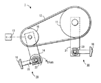
ベルト駆動システムの設計には従来から、多岐にわたる技術的アプローチが採用され、駆動有効寿命の全期間中にわたってベルトに適切な張力を加え、駆動トルクの変化に適切な対応が行われている。センター固定式駆動アプローチでは、ベルトに初期張力を加え、ローラまたはプーリのセンターはしっかりと固定されている。この配置では、駆動寿命中に張力の損失があることを前もって考慮し、大きな初期張力を加える必要がある。センターリニア移動式駆動形式では、片方または両方のプーリを相手方のプーリから離すようにリニアに移動して張力を加える。図1に示されているように、裏側/内側の張力を加えている駆動配置では、駆動プーリ2と被駆動プーリ3とが、ベルト4で接続されて駆動状態となる。駆動プーリ2には、モータ5から動力が伝えられる。一個または複数個の遊びプーリ(idler pulley)6で、ベルト4の内側または外側にバイアス力をかけ、張力を発生させる。バイアス力付加機構(biasing mechanism)の一例は、スプリング7で、これを遊びプーリ6とフレーム8との間で作用させる。フレーム8は、プーリシステムが用いられている装置のフレームである。
Traditionally, the design of belt drive systems has taken a wide variety of technical approaches, applying the appropriate tension to the belt throughout the useful life of the drive and responding appropriately to changes in drive torque. In the center fixed drive approach, an initial tension is applied to the belt and the center of the roller or pulley is firmly fixed. In this arrangement, it is necessary to apply a large initial tension in consideration of the loss of tension during the driving life. In the center linear movement drive type, one or both pulleys are linearly moved away from the other pulley to apply tension. As shown in FIG. 1, in the driving arrangement in which the backside / inside tension is applied, the driving
これらの技術的アプローチには、幾つかある障害または欠点が一つならず生じるのも珍しくない。そのような欠点としては、機構が複雑であったり、可動センターの配置状態および/または張力付加機構に起因して思いがけず駆動ダイナミクスに問題が起こったり、過大ベルト荷重および/またはベルトの逆方向曲がりに起因して部品の摩耗が促進されたり、ベルトの延び、フレームのクリープ、部品の摩耗、部品の所定の位置からの外れ(ベルト飛びを含む)のような要因に起因して修正不可能な張力変化が生じたり、温度や湿度の変化に起因して機械寸法が変化したりする等が、例として挙げられる。 It is not uncommon for these technical approaches to have one or more of several obstacles or disadvantages. Such disadvantages include complex mechanisms, unexpected drive dynamics due to the placement of the movable center and / or tensioning mechanism, excessive belt load and / or reverse belt bending. It is impossible to correct due to factors such as accelerated part wear due to belt extension, belt creep, frame creep, part wear, part slippage (including belt jumping) Examples include changes in tension and changes in machine dimensions due to changes in temperature and humidity.
実施の形態では、新しいセンター可動方式アプローチが提供されるが、この新規方法では、片側のプーリを他の相手側のプーリから引き離す、あるいは両方のプーリをそれぞれの相手側から引き離すことによって張力を加えるのは同じであるが、従来の技術のリニア形式の場合と異なって、回転(pivoting)形式で張力付加が行われる。この方法の利点は、トルクがシステムに加えられたとき、プーリに加えられるベルト荷重が自動調整(reorient)されるという事実を利用して得られる。実施の形態では、ある特定の方向にトルクが加えられると、他の機構を備える必要なしに、ベルト張力が比例的に増加するというような幾何学的形状が採用される。同様に、ある特定の方向と反対の方向にトルクが加えられると、ベルト張力は比例的に減少する。このようにして、従来技術の装置にかかわる欠点の多くは、これらの実施の形態では克服される。 The embodiment provides a new center moveable approach, in which the tension is applied by pulling one pulley away from the other, or pulling both pulleys away from each other. However, unlike the conventional linear type, tension is applied in a pivoting manner. The advantage of this method is obtained by taking advantage of the fact that when torque is applied to the system, the belt load applied to the pulley is reoriented. In an embodiment, a geometry is employed such that when torque is applied in a particular direction, the belt tension increases proportionally without the need for other mechanisms. Similarly, when torque is applied in a direction opposite to a certain direction, belt tension decreases proportionally. In this way, many of the disadvantages associated with prior art devices are overcome in these embodiments.
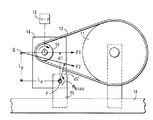
実施の形態では、センター可動方式のテンショナ付きベルト装置1の第一プーリ10は、好ましくは駆動プーリであるが、第二プーリ11、好ましくは被駆動プーリから離れて設置されている。第一と第二のプーリ10,11は、ベルト12の伝導で駆動されるように接続されている。駆動プーリ10はモータ13から回転駆動力を伝導され、次いで今度は駆動プーリ10が被駆動プーリ11に動力を伝導する。モータ13は、モータ板のようなモータ搭載板14に搭載するのが好ましい。モータ搭載板14は、テンショナが使用される装置のフレーム16に取り付けられた接続部15に対して自由に軸回転可能となっている。被駆動プーリ11は、好ましくは前記装置の回転要素17に接続される。例えば、印刷装置一般に採用される実施の形態では、この回転要素は、印字ドラム、定着ロールなどの回転要素であるが、他の回転要素を、実施の形態のテンショナ付きベルト装置で駆動することは可能である。
In the embodiment, the
実施の形態では、第一のバイアス力付加機構20を用い、回転形式で第一プーリ10を第二プーリ11から引き離すようにしてバイアス力を加えることよって、ベルト12に張力を持たせる。第一バイアス力付加機構20の作用によって、例えば、モータ板上または接続板上の回転中心点周りにバイアスモーメントMbiasが生じる。例えば、実施の形態では、モータ搭載板14と装置のフレーム16とに対してリニアに作用するバネ21を装着し得る。リニアに作用するバネ21には初期荷重をかけ、ベルト12に張力を持たせ、さらにバネ21の位置は回転中心点15からdbiasの距離になるようにし、回転中心点15の周りに初期モーメントMbias=dbias×Fbiasを生じさせることが、好ましい。ここに、Fbiasは最初はバネ21の初期荷重である。別の方法として、実施の形態では、ねじりバネ22を用い、これを回転中心点15の周りに装着し、初期荷重をかけ、回転中心点15の周りに初期Mbiasを生じさせることもし得る。モータ板上の回転中心点の位置の選択は、トルクがシステムに加えられたとき、ベルト紐材料の張力が再分配されるという事実を利用するように行うことが好ましい。実施の形態では、ある特定の方向にトルクが加えられると、他の機構を付加する必要なしに、ベルト張力が比例的に増加するというような幾何学的形状が採用される。
In the embodiment, the
実施の形態では、第二のバイアス力付加機構30を用い、第一プーリ10から第二プーリ11を引き離すバイアス力を加え、プーリ10,11双方を引き離してベルトに張力を持たせるのであるが、ここでも、これを、従来技術のリニア形式とは相異なり、回転形式で行い得る。プーリ取付板31などは、モータ搭載板14の場合と同様に、第二プーリ11とフレーム16との間に設置し得る。プーリ取付板31とフレーム16との間の接続部は自由に軸回転可能なことが好ましい。直線バネ32,ねじりバネ33、またはこれらと同様のものは、第二プーリ11を第一プーリ10から引き離すバイアス力を加えるのに用いられる。
In the embodiment, the second biasing
諸々の実施の形態は、例えば、印刷装置一般に用い得る。諸々の実施の形態は、相変化式インクジェット印刷装置に用い得る。諸々の実施の形態は、電子複写機、電子写真機、電子印刷機、例えば、電子写真式多機能コピー機/プリンタに用いるのに好適である。 The various embodiments can be used, for example, in general printing devices. Various embodiments may be used in a phase change ink jet printing apparatus. The various embodiments are suitable for use in electrophotographic copiers, electrophotographic machines, electronic printing machines, such as electrophotographic multifunction copiers / printers.
操作にあたって、トルクが加えられていないと、例えば、モータ/モータ板アセンブリにベルトが生じさせる合成力F0は、モータ板の回転中心点から距離d0にある作用ラインに沿って作用する。距離d0に生じる合成力F0の作用により、モーメントM0が発生する。モーメントM0は、バイアス力付加要素で発生されたモーメントMbiasと平衡を保つ。トルクがモータで加えられると、ベルト紐張力は再分配する。その結果、ベルト合成力は、回転中心点から新しい距離d1にある新しい作用ラインに沿って作用する。回転中心点周りのベルト合成力のモーメントは一定でなければならない(すなわち、Mbiasとの平衡が維持されなければならない)ので、このモーメントアームの変化により、ベルト合成力の大きさに対応する変化が生じる。 In operation, if no torque is applied, for example, the resultant force F 0 generated by the belt in the motor / motor plate assembly acts along an action line at a distance d 0 from the rotation center point of the motor plate. A moment M 0 is generated by the action of the resultant force F 0 generated at the distance d 0 . The moment M 0 is balanced with the moment M bias generated by the bias force addition element. As torque is applied by the motor, belt strap tension redistributes. As a result, the belt resultant force acts along a new action line at a new distance d1 from the center of rotation. Since the moment of the belt resultant force around the center of rotation must be constant (ie, the balance with M bias must be maintained), this moment arm change causes a change corresponding to the magnitude of the belt resultant force. Occurs.
より一般的に説明するため、図5と図6とを参照する。Pは、モータ搭載板の回転中心点を示す。ベルト紐とベルト合成力の仮想作用ラインとの交点であるQに関してモータ搭載板の位置決めを行うと、これらの実施の形態を用いることができる。ベルト紐の理論的交点である「Q」は、駆動解析に有用である。LxとLyは、Qに関するPの位置を示す。F1とF2とは、合成ベルト荷重で、相異なる条件下に生じるベルト紐張力のベクトル和である。F1は、モータのトルクが加えられないときの初期ベルト合成力であり、一方、F2は、トルクが加えられたときのベルト合成力である。F1はF2とは相異なる方向を有している。トルクを加えたことにより、ベルト紐の張力が異なったからである。各合成力F1とF2とは、回転中心点Pの周りにモーメントアームd1とd2とを有し、その結果各々モーメントM1とM2とが生じる。 For a more general description, reference is made to FIGS. P represents the rotation center point of the motor mounting plate. These embodiments can be used when the motor mounting plate is positioned with respect to Q, which is the intersection of the belt string and the virtual action line of the belt composite force. “Q”, which is a theoretical intersection of belt straps, is useful for drive analysis. L x and L y indicate the position of P with respect to Q. F1 and F2 are vector sums of belt string tensions generated under different conditions by the combined belt load. F1 is the initial belt composite force when no motor torque is applied, while F2 is the belt composite force when torque is applied. F1 has a different direction from F2. This is because the tension of the belt string is different by applying the torque. Each combined force F1 and F2 has moment arms d1 and d2 around the rotation center point P, resulting in moments M1 and M2, respectively.
操作に当たって、初期にはトルクが加えられていないので、バイアスモーメントMbiasがバイアス力付加機構でモータ板に加えられる。この場合、バイアス力付加機構は、例えば、回転中心点に設置されたねじりバネ、あるいは回転中心点から距離dbiasに設置された直線バネである。Mbiasにより、ベルト紐に初期張力が発生するが、その合成力がF1である。発生するM1は、Mbiasと大きさが等しく、方向が反対でなければならない。モータのトルクが加えられると、その結果ベルトに加わる荷重は、F2として加わり直す。このF2により、モーメントM2が発生する。このM2は、同様にMbiasと大きさが等しく、方向が反対でなければならない。図5の実施の形態の例で、d2はd1より短いということは、F2はF1より大きくなければならないということを意味する。ということは、ベルトにかかる荷重は、モータトルクが加わると増加するということを意味する。実施の形態では、回転中心点の位置を適切に微調整することにより、一層大きな駆動容量が得られる。反対方向のモータトルクが図5の例のシステムに加えられると、ベルト荷重と駆動容量とが減少することに注意する。実施の形態の適用を可能にするにはプーリのサイズが相異なる必要はない。このことは、例えば、図6に見られる通りである。この図では、回転中心点周りの個々のベルト紐荷重のモーメント寄与分の解析が可能である。 In operation, since no torque is initially applied, the bias moment M bias is applied to the motor plate by the bias force adding mechanism. In this case, the bias force adding mechanism is, for example, a torsion spring installed at the rotation center point, or a linear spring installed at a distance d bias from the rotation center point. The initial tension is generated in the belt string due to M bias , but the resultant force is F1. The generated M1 must be equal in magnitude and opposite in direction to Mbias . When the motor torque is applied, the resulting load on the belt is reapplied as F2. By this F2, a moment M2 is generated. This M2 must also be equal in magnitude and opposite in direction to Mbias . In the example of the embodiment of FIG. 5, the fact that d2 is shorter than d1 means that F2 must be larger than F1. This means that the load applied to the belt increases when motor torque is applied. In the embodiment, a larger driving capacity can be obtained by appropriately fine-tuning the position of the rotation center point. Note that when opposite direction motor torque is applied to the system of the example of FIG. 5, belt load and drive capacity decrease. The pulleys need not have different sizes in order to be able to apply the embodiment. This is, for example, as seen in FIG. In this figure, it is possible to analyze the moment contribution of individual belt strap loads around the rotation center point.
1 センター可動式テンショナ付きベルト装置、2,10 駆動プーリ、3,11 被駆動プーリ、4,12 ベルト、5,13 モータ、6 遊びプーリ、7 バネ、 8,16 フレーム、10 第一プーリ、11 第二プーリ、14 モータ搭載板、15 接続部、17 回転要素、20 第一バイアス力付加機構、21,32 直線バネ、22,33 ねじりバネ、30 第二バイアス力付加機構、31 プーリ取付板。 1 Belt device with movable center tensioner, 2,10 Drive pulley, 3,11 Driven pulley, 4,12 Belt, 5,13 Motor, 6 Play pulley, 7 Spring, 8,16 Frame, 10 First pulley, 11 Second pulley, 14 Motor mounting plate, 15 connection part, 17 Rotating element, 20 First bias force applying mechanism, 21, 32 Linear spring, 22, 33 Torsion spring, 30 Second bias force applying mechanism, 31 Pulley mounting plate.
Claims (3)
第一と第二のプーリ間に巻かれたベルトと、
回転形式で第一プーリを第二プーリから引き離すように引っ張る第一バイアス力付加機構と、
を備え、
トルクがプーリに加えられると、プーリにかかるベルト荷重が自動調整されることを特徴とするセンター可動式テンショナ付きベルト駆動装置。 First and second pulleys;
A belt wound between the first and second pulleys;
A first bias force application mechanism for pulling the first pulley away from the second pulley in a rotating manner;
With
A belt drive device with a center movable tensioner, wherein the belt load applied to the pulley is automatically adjusted when torque is applied to the pulley.
フレームに取り付けられた軸回転自在のモータ搭載板と、
軸回転自在のモータ搭載板の回転中心点であって、この周りに回転自在のモータ搭載板が回転し、これを通って回転自在のモータ搭載板がフレームに取り付けられている回転中心点と、
前記モータ搭載板に取り付けられた第一プーリであって、前記モータ搭載板に搭載されたモータから駆動力を得る第一プーリと、
テンショナが用いられている機械要素に取り付けられた第二プーリと、
第一プーリと第二プーリの間に巻かれたベルトであって、前記モータからの駆動力を、第一プーリを経て第二プーリに伝導するベルトと、
前記モータ搭載板に取り付けられた第一バイアス力付加装置であって、第一プーリを第二のプーリから引き離すようにバイアス力をかけ、モータからの駆動力に変化が生じると、ベルト張力のみならず、前記モータ搭載板に加わるバイアスモーメントにも変化を生じさせる第一バイアス力付加装置と、
を備えることを特徴とするテンショナ付きベルト駆動装置。 A belt drive with a tensioner,
A shaft mounting motor mounted plate attached to the frame,
A rotation center point of a rotatable motor mounting plate around which the rotatable motor mounting plate rotates, and through which the rotatable motor mounting plate is attached to the frame;
A first pulley attached to the motor mounting plate, the first pulley obtaining driving force from the motor mounted on the motor mounting plate;
A second pulley attached to the machine element in which the tensioner is used;
A belt wound between a first pulley and a second pulley, wherein the driving force from the motor is transmitted to the second pulley via the first pulley;
The first bias force applying device attached to the motor mounting plate, when a bias force is applied so as to separate the first pulley from the second pulley, and a change occurs in the driving force from the motor, only the belt tension. A first bias force applying device that causes a change in the bias moment applied to the motor mounting plate;
A belt drive device with a tensioner, comprising:
Applications Claiming Priority (1)
| Application Number | Priority Date | Filing Date | Title |
|---|---|---|---|
| US10/721,386 US20050113197A1 (en) | 2003-11-25 | 2003-11-25 | Bidirectional belt tensioning approach |
Publications (2)
| Publication Number | Publication Date |
|---|---|
| JP2005155916A true JP2005155916A (en) | 2005-06-16 |
| JP2005155916A5 JP2005155916A5 (en) | 2007-06-14 |
Family
ID=34591786
Family Applications (1)
| Application Number | Title | Priority Date | Filing Date |
|---|---|---|---|
| JP2004334037A Withdrawn JP2005155916A (en) | 2003-11-25 | 2004-11-18 | Belt driving device with tensioner |
Country Status (5)
| Country | Link |
|---|---|
| US (1) | US20050113197A1 (en) |
| JP (1) | JP2005155916A (en) |
| CN (1) | CN1621712A (en) |
| BR (1) | BRPI0405138A (en) |
| CA (1) | CA2487782C (en) |
Cited By (1)
| Publication number | Priority date | Publication date | Assignee | Title |
|---|---|---|---|---|
| JP2017194174A (en) * | 2016-04-18 | 2017-10-26 | 東芝ホームテクノ株式会社 | Heating cooker |
Families Citing this family (20)
| Publication number | Priority date | Publication date | Assignee | Title |
|---|---|---|---|---|
| KR100810610B1 (en) * | 2006-10-25 | 2008-03-07 | 삼성전자주식회사 | Belt tention tuning apparatus and robot arm having the same |
| KR100787127B1 (en) * | 2007-05-11 | 2007-12-21 | 김용길 | Pulley-adjustment-device for pulley drive system |
| CA2594064A1 (en) * | 2007-07-19 | 2009-01-19 | Alcan International Ltd. | Pneumatic base for facilitating the installation and tensioning of a drive belt |
| JP4577626B2 (en) * | 2008-02-08 | 2010-11-10 | 株式会社ダイフク | Belt drive |
| CN101829950B (en) * | 2010-05-06 | 2012-10-17 | 满城县永红铸造机械有限公司 | Safe and high-speed grinding wheel machine |
| CN103668934B (en) * | 2012-09-18 | 2017-05-31 | 长园和鹰智能科技有限公司 | It is a kind of to realize the mechanism that sideline judge's function is walked on automatic cutting machines side |
| US9303734B2 (en) * | 2013-08-09 | 2016-04-05 | Gates Corporation | Belt transmission |
| DE102014112885A1 (en) * | 2014-09-08 | 2016-03-10 | Claas Selbstfahrende Erntemaschinen Gmbh | Schwenkvariator |
| CN104405636A (en) * | 2014-11-22 | 2015-03-11 | 中联重机股份有限公司 | Hydraulic generating device and agricultural machine with same |
| DE102014226906B4 (en) * | 2014-12-23 | 2020-04-02 | Voith Patent Gmbh | Method for operating a chain drive and arrangement with a chain drive |
| US11060590B2 (en) | 2016-09-12 | 2021-07-13 | Hewlett-Packard Development Company, L.P. | Scanning device with belt tensioning system mounted on a plate of a scan bar having at least pulley and spring coupled to first and second planars of the plate |
| CN107241945A (en) * | 2017-06-05 | 2017-10-13 | 宁波市种植业管理总站 | Drag seedling machine in a kind of rice mechanical transplanting rice seedling bed |
| US20210148440A1 (en) * | 2018-05-17 | 2021-05-20 | Hewlett-Packard Development Company, L.P. | Belt tensioning system |
| CN109876965A (en) * | 2019-04-15 | 2019-06-14 | 东莞倍力扣金属制品有限公司 | Jam nut gluing processes conveying device |
| KR20210115688A (en) * | 2020-03-16 | 2021-09-27 | 한화테크윈 주식회사 | Camera Assembly |
| CN112271035B (en) * | 2020-10-22 | 2022-03-01 | 合肥神马科技集团有限公司 | Transmission method for frame winch |
| CN113319000A (en) * | 2021-06-28 | 2021-08-31 | 华磊(嘉兴)智能科技有限公司 | Mechanism for detecting precise screws by utilizing four groups of servo motor operation steel wires |
| CN113733065A (en) * | 2021-09-06 | 2021-12-03 | 珠海格力电器股份有限公司 | Transmission and industrial robot |
| KR20230039289A (en) * | 2021-09-14 | 2023-03-21 | 한화비전 주식회사 | Camera driving device having a plurality of timing belts |
| US11851281B2 (en) * | 2021-12-15 | 2023-12-26 | Xerox Corporation | Automatic tensioning tool for a belt of a printing device |
Family Cites Families (18)
| Publication number | Priority date | Publication date | Assignee | Title |
|---|---|---|---|---|
| US615905A (en) * | 1898-12-13 | richards | ||
| US1319066A (en) * | 1919-10-21 | Hugo obob | ||
| US604081A (en) * | 1898-05-17 | Willard p | ||
| US740982A (en) * | 1903-06-05 | 1903-10-06 | Cons Railway Electric Lighting And Equipment Company | Mechanism for driving dynamos on railway-trucks. |
| US769920A (en) * | 1903-11-02 | 1904-09-13 | Charles M Gould | Dynamo-mounting for railway-car trucks. |
| US1196927A (en) * | 1915-02-01 | 1916-09-05 | Alanson P Brush | Transmission mechanism for starting and lighting apparatus. |
| US1282198A (en) * | 1917-11-28 | 1918-10-22 | Binghamton Washing Machine Co | Belt-tightener. |
| US1615544A (en) * | 1923-10-04 | 1927-01-25 | Safety Car Heating & Lighting | Power transmission |
| US1868533A (en) * | 1929-07-01 | 1932-07-26 | Carl E Johnson | Motor construction |
| US2235972A (en) * | 1938-06-25 | 1941-03-25 | Rca Corp | Sound motion picture apparatus |
| US3631734A (en) * | 1970-05-27 | 1972-01-04 | Caterpillar Tractor Co | Self-adjusting belt tightener |
| GB1390013A (en) * | 1971-03-11 | 1975-04-09 | Plenty Son Ltd | Automatic belt tensioning device |
| US3702570A (en) * | 1971-10-07 | 1972-11-14 | Dayco Corp | Drive for vehicle mounted alternator |
| US3861657A (en) * | 1973-04-05 | 1975-01-21 | Royal W Sims | Chain tensioning device |
| US3924483A (en) * | 1974-11-25 | 1975-12-09 | Gen Motors Corp | Belt driven accessory for vehicles with automatic belt tensioner |
| US4165466A (en) * | 1977-05-25 | 1979-08-21 | Dayco Corporation | Drive apparatus for vehicle mounted generator |
| US4241614A (en) * | 1979-06-04 | 1980-12-30 | Chouinard Raymond J | Power take-off |
| CA1246043A (en) * | 1985-06-03 | 1988-12-06 | Raymond Johnson | Motor mount assembly |
-
2003
- 2003-11-25 US US10/721,386 patent/US20050113197A1/en not_active Abandoned
-
2004
- 2004-11-18 CA CA002487782A patent/CA2487782C/en not_active Expired - Fee Related
- 2004-11-18 JP JP2004334037A patent/JP2005155916A/en not_active Withdrawn
- 2004-11-22 BR BR0405138-6A patent/BRPI0405138A/en not_active IP Right Cessation
- 2004-11-25 CN CN200410091793.9A patent/CN1621712A/en active Pending
Cited By (1)
| Publication number | Priority date | Publication date | Assignee | Title |
|---|---|---|---|---|
| JP2017194174A (en) * | 2016-04-18 | 2017-10-26 | 東芝ホームテクノ株式会社 | Heating cooker |
Also Published As
| Publication number | Publication date |
|---|---|
| CA2487782A1 (en) | 2005-05-25 |
| US20050113197A1 (en) | 2005-05-26 |
| CA2487782C (en) | 2008-10-07 |
| BRPI0405138A (en) | 2005-07-19 |
| CN1621712A (en) | 2005-06-01 |
Similar Documents
| Publication | Publication Date | Title |
|---|---|---|
| JP2005155916A (en) | Belt driving device with tensioner | |
| EP3102850B1 (en) | Tensioner | |
| US8353795B2 (en) | Two-armed tensioner for the drive belt of a motor vehicle | |
| TWI335873B (en) | Belt tension adjusting mechanism | |
| JP2005155916A5 (en) | ||
| JP2006306508A (en) | Taping device | |
| EP3114370A1 (en) | Belt tensioner with supplemental force element | |
| JP3339800B2 (en) | Belt drive | |
| JPH09202533A (en) | Tension regulating device for wire | |
| US4093150A (en) | Method and apparatus for providing constant magnetic tape tension | |
| US6058286A (en) | Transfer unit of electrophotographic printer | |
| JP4610472B2 (en) | Spring device using the tightening force | |
| JP2732620B2 (en) | Photoconductor drive unit | |
| JP2009115899A (en) | Back transmission type projector device | |
| JP2681276B2 (en) | Journal paper take-up mechanism | |
| JP2005140249A (en) | Tension control device of winding type rotation transmitting apparatus | |
| JP2002145524A (en) | Device for controlling winding frame of textile machinery | |
| JPH0522514Y2 (en) | ||
| JPH1029771A (en) | Torque generator and reel having the same | |
| JPH0286483A (en) | Printer | |
| JP2005351423A (en) | Belt tension mechanism | |
| JP4031010B2 (en) | Printer paper transport mechanism | |
| JPH06147280A (en) | Belt transmission device | |
| JPH03264388A (en) | Ribbon take-up device | |
| JPH06109087A (en) | Belt transmission mechanism |
Legal Events
| Date | Code | Title | Description |
|---|---|---|---|
| A521 | Request for written amendment filed |
Free format text: JAPANESE INTERMEDIATE CODE: A523 Effective date: 20070425 |
|
| A621 | Written request for application examination |
Free format text: JAPANESE INTERMEDIATE CODE: A621 Effective date: 20070425 |
|
| A977 | Report on retrieval |
Free format text: JAPANESE INTERMEDIATE CODE: A971007 Effective date: 20091120 |
|
| A761 | Written withdrawal of application |
Free format text: JAPANESE INTERMEDIATE CODE: A761 Effective date: 20091126 |