JP2005152819A - Centrifuge and rotor for centrifuge - Google Patents
Centrifuge and rotor for centrifuge Download PDFInfo
- Publication number
- JP2005152819A JP2005152819A JP2003396750A JP2003396750A JP2005152819A JP 2005152819 A JP2005152819 A JP 2005152819A JP 2003396750 A JP2003396750 A JP 2003396750A JP 2003396750 A JP2003396750 A JP 2003396750A JP 2005152819 A JP2005152819 A JP 2005152819A
- Authority
- JP
- Japan
- Prior art keywords
- bucket
- rotor
- annular groove
- pin
- centrifuge
- Prior art date
- Legal status (The legal status is an assumption and is not a legal conclusion. Google has not performed a legal analysis and makes no representation as to the accuracy of the status listed.)
- Pending
Links
Images


Classifications
-
- B—PERFORMING OPERATIONS; TRANSPORTING
- B04—CENTRIFUGAL APPARATUS OR MACHINES FOR CARRYING-OUT PHYSICAL OR CHEMICAL PROCESSES
- B04B—CENTRIFUGES
- B04B5/00—Other centrifuges
- B04B5/04—Radial chamber apparatus for separating predominantly liquid mixtures, e.g. butyrometers
- B04B5/0407—Radial chamber apparatus for separating predominantly liquid mixtures, e.g. butyrometers for liquids contained in receptacles
- B04B5/0414—Radial chamber apparatus for separating predominantly liquid mixtures, e.g. butyrometers for liquids contained in receptacles comprising test tubes
- B04B5/0421—Radial chamber apparatus for separating predominantly liquid mixtures, e.g. butyrometers for liquids contained in receptacles comprising test tubes pivotably mounted
Abstract
Description
本発明は、遠心機および遠心機用ロータに関するものである。 The present invention relates to a centrifuge and a centrifuge rotor.
従来の遠心機用スイングロータを図5、図6、を用いて説明する。遠心機用スイングロータには種々のものがあるが、一般的にはロータボディの外周部に設けられている1対のロータアーム部1で形成されるバケット収納部12の対向する側面にスイングの支点となる円筒状のロータピン2が配置されている。さらに試料を入れるバケット5の両側面にはロータピン2に係合するようにピン係合部7を形成し、ロータピン2と係合してスイングする。ロータピン2はロータアーム部1と一体化もしくは円筒状の別部材をロータアーム部1に設けた貫通穴に取り付ける場合がある。どちらの場合も、ロータが回転すると遠心力がバケット5に作用してバケット回転中心6を中心にして、水平方向に90°にスイングできる構造となっている。また、バケットの上面に密閉用のキャップを設ける場合もある。
A conventional centrifuge swing rotor will be described with reference to FIGS. There are various types of swing rotors for centrifuges. In general, swings are placed on opposite sides of a bucket storage portion 12 formed by a pair of
従来は、このロータピン2とバケット5のピン係合部7の接触部は、バケット5や試料14の遠心力の荷重に耐えるように接触面積を増やすように相似形状で形成されている。そのため接触部分が多く、繰り返しのスイングによる磨耗でロータピン2とピン係合部7の接触部が傷つくため、接触抵抗が増加しスイング不良を起こしやすくなり、最悪の場合はロータの回転が停止してもバケットが水平状態から戻らないことがある。また、スイングによる磨耗で生じた傷により、バケット5の接触境界8にある傷が切欠きとなりき裂が発生し、き裂先端近傍に接触応力特異点が生じるためバケット5の短寿命の要因となっていた。
Conventionally, the contact portion of the
例えば、特許公開2002−113388に記載されているように、ロータピンの先端が外径方向にテーパ形状に広がり遠心中はロータピンとバケット凹部が線接触し、停止中は点もしくは線接触となり接触面が傷つき難くスイング不良が起きにくい手段を設けることが提案されている。遠心中はバケットとピン間が線接触となることについては記載されているが、バケットとロータピン間が常に点接触となるような構成については何も記載されていない。 For example, as described in Japanese Patent Laid-Open No. 2002-113388, the tip of the rotor pin extends in a tapered shape in the outer diameter direction, and the rotor pin and the bucket recess are in line contact during centrifugation, and during stop, the contact surface becomes a point or line contact and the contact surface becomes It has been proposed to provide means that are less likely to be damaged and that cause poor swing failure. While it is described that the bucket and the pin are in line contact during centrifugation, nothing is described about the configuration in which the bucket and the rotor pin are always in point contact.
また、実開平6−39140に記載されているように、係合ピンとバケットを線接触させて接触部分を大きくする構造が提案されており、また、実開平6−39141に記載されているように、バケットの係合部の反対面に補強部材を設けることが提案されているが、バケットの係合部にロータピンの円周外周方向に環状の溝を設けたことについては何も記載されていない。 Further, as described in Japanese Utility Model Laid-Open No. 6-39140, a structure has been proposed in which the engagement pin and the bucket are brought into line contact with each other to increase the contact portion, and as described in Japanese Utility Model Laid-Open No. Hei 6-39141. Although it has been proposed to provide a reinforcing member on the opposite surface of the engaging portion of the bucket, nothing is described about providing an annular groove in the circumferential outer peripheral direction of the rotor pin in the engaging portion of the bucket .
上記した従来のスイングロータでは、繰返し使用するうちにロータピンとバケットの係合面で固着する現象が発生することがある。この現象は、ロータボディやバケットが遠心力によって変形し、その際、係合部の接触部で磨耗粉やバケットの回動方向の擦り傷等が発生し、揺動し難くなることに起因する。この場合、対称位置にあるバケットの揺動状態が不揃いとなりアンバランス運転となって回転振動が大きくなったり、回転停止時にバケットが傾いたまま停止して試料がこぼれてしまい、最悪の場合、ロータや遠心機の損傷に繋がり使用者の財産を損ねる可能性があった。また、遠心中にバケットとロータピンの接触境界の部分にバケットの変形によるロータピン中心軸方向に引張り荷重が働き、上記した擦り傷が切欠き効果となり、応力集中を起こし、バケットの寿命が低下する欠点があった。本発明の目的は、前述の遠心分離機用スイングロータの問題を解消し、バケットの揺動動作が常にスムーズに回動できる構造を提供し、さらにバケットの寿命を改善することである。 In the above-described conventional swing rotor, a phenomenon that the rotor pin and the bucket are fixed to each other during repeated use may occur. This phenomenon is caused by the fact that the rotor body and the bucket are deformed by the centrifugal force, and at this time, wear powder, scratches in the rotation direction of the bucket, and the like are generated at the contact portion of the engaging portion, and it becomes difficult to swing. In this case, the swinging state of the buckets at the symmetric position becomes uneven and unbalanced operation results in increased rotational vibration, or when the rotation stops, the bucket stops tilting and the sample spills out. This could damage the centrifuge and damage the user's property. In addition, a tensile load acts on the rotor pin center axis direction due to the deformation of the bucket at the contact boundary portion between the bucket and the rotor pin during centrifugation, and the above-mentioned scratch becomes a notch effect, causing stress concentration and reducing the life of the bucket. there were. An object of the present invention is to eliminate the above-described problem of the swing rotor for a centrifuge, to provide a structure in which the swinging motion of the bucket can always be smoothly rotated, and to improve the life of the bucket.
駆動装置によって回転される駆動軸と、該回転軸に装着されるロータボディと、該ロータボディに形成されたバケット収納部と該バケット収納部に配置された円柱状のピン部と、該ピン部とピン係合部を介してし揺動可能に配される複数のバケットを有するスイングロータを備えた遠心機において、前記ピン係合部に環状溝を設け、前記ピン部端面と、ピン係合部端面との隙間よりも、係合部環状溝の幅の方が大きくなるよう構成することによって達成される。 A drive shaft that is rotated by a drive device, a rotor body that is mounted on the rotation shaft, a bucket storage portion formed on the rotor body, a columnar pin portion disposed in the bucket storage portion, and the pin portion And a centrifuge having a swing rotor having a plurality of buckets arranged so as to be swingable via the pin engaging portion, the pin engaging portion is provided with an annular groove, and the pin portion end surface and the pin engaging portion This is achieved by configuring the engagement portion annular groove to be larger in width than the gap between the portion end faces.
さらに、前記係合部環状溝に環状溝アール部を設け、該環状溝アール部の曲率半径を前記係合部環状溝の1/2に設けることによって達成される。
また、駆動装置によって回転される駆動軸と、該回転軸に装着されるロータボディと、該ロータボディに形成されたバケット収納部と該バケット収納部に配置された円柱状のピン部と、該ピン部とピン係合部を介してし揺動可能に配される複数のバケットを備えたスイングロータにおいて、前記ピン係合部に環状溝を設け、前記ピン部端面と、ピン係合部端面との隙間よりも、係合部環状溝の幅の方が大きくなるよう構成されることによって達成される。
Further, this is achieved by providing an annular groove round portion in the engagement portion annular groove, and providing a radius of curvature of the annular groove round portion to ½ of the engagement portion annular groove.
A driving shaft rotated by the driving device; a rotor body mounted on the rotating shaft; a bucket storage portion formed on the rotor body; a columnar pin portion disposed in the bucket storage portion; In a swing rotor having a plurality of buckets arranged so as to be swingable via a pin portion and a pin engaging portion, an annular groove is provided in the pin engaging portion, and the pin portion end surface and the pin engaging portion end surface This is achieved by configuring the engagement portion annular groove to be wider than the clearance.
さらに、前記係合部環状溝に環状溝アール部を設け、該環状溝アール部の曲率半径を前記係合部環状溝の1/2に設けることによって達成される。 Further, this is achieved by providing an annular groove round portion in the engagement portion annular groove, and providing a radius of curvature of the annular groove round portion to ½ of the engagement portion annular groove.
以上説明したように、本発明によれば、遠心機用スイングロータのスイング性を向上し、更にバケットの長寿命化が図れ、安全性が高いバケット取付け構造を提供することができる。 As described above, according to the present invention, the swingability of the centrifuge swing rotor can be improved, the life of the bucket can be extended, and a bucket mounting structure with high safety can be provided.
本発明遠心機用スイングロータの一実施形態を図1、図2、図3、図4および図7を用いて説明する。
図1は遠心機20に本発明の遠心機用スイングロータ10と、この遠心機用スイングロータ1に揺動可能に支持されたバケットの装着状態を示す断面図である。点線で描かれたバケット5はロータ10が停止中の状態を表し、実線で描かれているのが、ロータ10が回転中の状態を表している。
An embodiment of a swing rotor for a centrifuge of the present invention will be described with reference to FIGS. 1, 2, 3, 4 and 7.
FIG. 1 is a cross-sectional view showing a
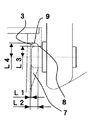
遠心機用スイングロータ10は、遠心機20の回転室22に突出するよう配置された駆動装置23によって回転駆動されるよう配置され、回転室22の上部には、遠心機20からロータ10、バケット5または、試料14の入った試料容器13を取出すためのドア25が開閉可能の配置されている。図3は、ロータピン2にバケット5を取り付けた状態を示す断面図であり、1はロータアーム部、2はロータピン、3は係合部環状溝、5はバケット、6はバケット回転中心、8は接触境界、9は環状溝アール部である。なお、本実施例ではロータピン2とロータボディ11が別部品で構成されているが、ロータピン2とロータボディ11は一体に設けられていてもよい。
The
駆動装置23の回転軸24を介して遠心機用スイングロータが回転することにより、ロータのバケット収納部12に揺動可能に配される複数のバケット5が遠心力によりバケット回転中心6を中心に水平方向に90°スイングする構造となっている。図2はロータピン2付近の拡大断面図である。図5は、図3のA−A断面図でバケット5とロータピン2の接触部を示し、2はロータピン、7はピン係合部である。
The centrifuge swing rotor rotates through the
本実施形態で最も重要な点は、隙間を有するよう形成された係合部環状溝3の溝幅L2がバケット5とロータピンの端面の距離L1より大きく(L2>L1)となるように構成されている点と、ロータピン2にバケット5セットした状態での、バケット回転中心6(ロータピン2の中心軸)ロータピン2の外形面までの距離L3(ロータピン2の半径)よりもバケット回転中心6と係合部環状溝3の頂点までの距離L4が大きく(L4>L3)なるよう設けらている点である。
The most important point in the present embodiment is that the groove width L2 of the engaging portion
係合部環状溝3が形成される理由は2つある。1つは、ロータピン2とバケット5の接触位置4の線接触部を極力小さくするか、もしくは点接触にするためで、線接触部を極力小さくするか、もしくは点接触にすることによりロータピン2とバケット5の係合部での磨耗粉や擦り傷の範囲が減少することにより、摩擦抵抗を低減することができバケットの揺動が容易となり、バケット5とロータピンの固着する現象が大幅に改善されるためである。
There are two reasons why the engaging portion
ただし、接触部分が減少するため、遠心中のバケット5とロータピン2の接触部分の圧力が従来の構造のものと比較して大きくなるが、接触位置4部分に生じる応力は圧縮応力が支配的でありバケットの寿命に及ぼす影響は殆ど無い。実際に図3に記載した本発明の実施形態と従来形態の図3、図4と寿命比較した結果、本発明の実施形態は従来形態と同等以上の寿命を示した。
However, since the contact portion is reduced, the pressure at the contact portion between the
もう1つの理由は、限られた空間でより大きなアール部を設けるためである。環状溝アール部9には、バケット5自身とその中に装填される試料14および試料容器13の遠心力による荷重が作用するため応力が集中してしまう。そのため、環状溝アール部9は大きければ大きいほど応力を緩和できる。本実施例では、環状溝アール部9の曲率半径は係合部環状溝3の溝幅L2の1/2(L2/2)となっている。なお、応力的に余裕がある場合は、曲率半径を係合部環状溝3の溝幅L2の1/2以下に設けても良いことは言うまでもない。
Another reason is to provide a larger rounded portion in a limited space. Stress is concentrated on the annular groove rounded portion 9 due to the load of the
また、本発明の形態にすることにより、接触境界8部分にはバケット5の変形によるバケット回転中心6方向引張り荷重が働かないので、バケット5とロータピン2の摺動部に生じたバケットの回動方向の擦り傷による応力集中が生じないため、バケット5の寿命が向上する。
Further, by adopting the form of the present invention, since the tensile load in the direction of the
以上のことから、従来のスイングロータで問題であった係合部の接触部の磨耗粉や擦り傷等による揺動の悪化による回転振動の増大や、バケット5とロータピン2の接触位置4に作用していた応力集中によるバケットの強度低下が、バケット5に係合部環状溝3を設け、かつ環状溝にアール部9を設ける構造にすれば、これら問題を解決することができる。
From the above, it acts on the
1はロータアーム部、2はロータピン、3は係合部環状溝、4は接触位置、5はバケット、6はバケット回転中心、7はピン係合部、8は接触境界、9は環状溝アール部、10は遠心機用スイングロータ、11はロータボディ、12はバケット収納部、13は試料容器、14は試料、20は遠心機、22は回転室、23は駆動装置、24は回転軸、25はドアである。
DESCRIPTION OF
Claims (4)
The swing rotor according to claim 1, wherein an annular groove round portion is provided in the engagement portion annular groove, and a radius of curvature of the annular groove round portion is provided at a half of the engagement portion annular groove.
Priority Applications (1)
| Application Number | Priority Date | Filing Date | Title |
|---|---|---|---|
| JP2003396750A JP2005152819A (en) | 2003-11-27 | 2003-11-27 | Centrifuge and rotor for centrifuge |
Applications Claiming Priority (1)
| Application Number | Priority Date | Filing Date | Title |
|---|---|---|---|
| JP2003396750A JP2005152819A (en) | 2003-11-27 | 2003-11-27 | Centrifuge and rotor for centrifuge |
Publications (2)
| Publication Number | Publication Date |
|---|---|
| JP2005152819A true JP2005152819A (en) | 2005-06-16 |
| JP2005152819A5 JP2005152819A5 (en) | 2007-01-18 |
Family
ID=34722101
Family Applications (1)
| Application Number | Title | Priority Date | Filing Date |
|---|---|---|---|
| JP2003396750A Pending JP2005152819A (en) | 2003-11-27 | 2003-11-27 | Centrifuge and rotor for centrifuge |
Country Status (1)
| Country | Link |
|---|---|
| JP (1) | JP2005152819A (en) |
Cited By (3)
| Publication number | Priority date | Publication date | Assignee | Title |
|---|---|---|---|---|
| JP2012101203A (en) * | 2010-11-12 | 2012-05-31 | Hitachi Koki Co Ltd | Swing rotor for centrifugal separator and centrifugal separator |
| WO2016052265A1 (en) * | 2014-09-30 | 2016-04-07 | 日立工機株式会社 | Centrifuge and swing rotor for centrifuge |
| EP3311925A1 (en) * | 2016-10-24 | 2018-04-25 | Sigma Laborzentrifugen GmbH | Centrifuge bucket and centrifuge |
-
2003
- 2003-11-27 JP JP2003396750A patent/JP2005152819A/en active Pending
Cited By (6)
| Publication number | Priority date | Publication date | Assignee | Title |
|---|---|---|---|---|
| JP2012101203A (en) * | 2010-11-12 | 2012-05-31 | Hitachi Koki Co Ltd | Swing rotor for centrifugal separator and centrifugal separator |
| US20120190527A1 (en) * | 2010-11-12 | 2012-07-26 | Hitachi Koki Co., Ltd., | Swing rotor for centrifugal separator and centrifugal separator |
| US8469870B2 (en) * | 2010-11-12 | 2013-06-25 | Hitachi Koki Co., Ltd. | Swing rotor having improved holding pin for centrifugal separator and centrifugal separator including the same |
| WO2016052265A1 (en) * | 2014-09-30 | 2016-04-07 | 日立工機株式会社 | Centrifuge and swing rotor for centrifuge |
| JPWO2016052265A1 (en) * | 2014-09-30 | 2017-04-27 | 日立工機株式会社 | Centrifuge and swing rotor for centrifuge |
| EP3311925A1 (en) * | 2016-10-24 | 2018-04-25 | Sigma Laborzentrifugen GmbH | Centrifuge bucket and centrifuge |
Similar Documents
| Publication | Publication Date | Title |
|---|---|---|
| KR950001109A (en) | Swivel scroll drive device of scroll compressor | |
| JP2005152819A (en) | Centrifuge and rotor for centrifuge | |
| US20100021328A1 (en) | Scroll compressor | |
| JP2006315675A (en) | Device for rotating/connecting wheel and tachometer of aircraft | |
| JP6195023B2 (en) | Centrifuge and swing rotor for centrifuge | |
| JP6274089B2 (en) | Scroll compressor | |
| CN105508529A (en) | Asymmetric high-damping belt tensioning pulley | |
| JPWO2019230151A1 (en) | Angle detection sensor | |
| JP3760754B2 (en) | Centrifuge rotor | |
| JP5116533B2 (en) | Sliding bearing device and pump device | |
| KR20060122471A (en) | Low-torque pack seal structure for automobile wheel bearing | |
| KR200143365Y1 (en) | A device preventing turn-table of cd drive from deorbit | |
| JP2010082514A (en) | Rotor for centrifuge and centrifuge | |
| CN218843226U (en) | Drag line type power supply device | |
| JP4713457B2 (en) | Bearing holder for variable displacement swash plate pump / motor | |
| US20020035023A1 (en) | Centrifugal separator and rotor thereof | |
| CN214788903U (en) | Gear structure of motorcycle engine balance shaft | |
| JP2005152819A5 (en) | ||
| CN213036027U (en) | Universal cable guider | |
| CN210490649U (en) | Submersible motor adopting magnetic suspension thrust bearing | |
| KR200389212Y1 (en) | structure of bearing supports with a motor | |
| CN206347024U (en) | A kind of automobile gimbal | |
| KR100522968B1 (en) | Rotator Device of Crane grab | |
| CN106246935A (en) | A kind of batch (-type) hard-sealing zero friction butterfly valve | |
| KR100405761B1 (en) | Oil seal assembly |
Legal Events
| Date | Code | Title | Description |
|---|---|---|---|
| A521 | Written amendment |
Free format text: JAPANESE INTERMEDIATE CODE: A523 Effective date: 20061122 |
|
| A621 | Written request for application examination |
Free format text: JAPANESE INTERMEDIATE CODE: A621 Effective date: 20061122 |
|
| A977 | Report on retrieval |
Free format text: JAPANESE INTERMEDIATE CODE: A971007 Effective date: 20081107 |
|
| A131 | Notification of reasons for refusal |
Free format text: JAPANESE INTERMEDIATE CODE: A131 Effective date: 20081118 |
|
| A02 | Decision of refusal |
Free format text: JAPANESE INTERMEDIATE CODE: A02 Effective date: 20090421 |