JP2005138946A - Work vehicle - Google Patents
Work vehicle Download PDFInfo
- Publication number
- JP2005138946A JP2005138946A JP2003376455A JP2003376455A JP2005138946A JP 2005138946 A JP2005138946 A JP 2005138946A JP 2003376455 A JP2003376455 A JP 2003376455A JP 2003376455 A JP2003376455 A JP 2003376455A JP 2005138946 A JP2005138946 A JP 2005138946A
- Authority
- JP
- Japan
- Prior art keywords
- jack
- brake
- jacks
- ground
- operating
- Prior art date
- Legal status (The legal status is an assumption and is not a legal conclusion. Google has not performed a legal analysis and makes no representation as to the accuracy of the status listed.)
- Pending
Links
Images


Landscapes
- Forklifts And Lifting Vehicles (AREA)
- Vehicle Cleaning, Maintenance, Repair, Refitting, And Outriggers (AREA)
Abstract
Description
本発明は、前輪および後輪を有して走行可能な車体に、これら前後輪に隣接して車体を持ち上げ支持する複数のジャッキを備えた作業車に関する。 The present invention relates to a work vehicle provided with a plurality of jacks for lifting and supporting a vehicle body adjacent to the front and rear wheels on a vehicle body having a front wheel and a rear wheel.
上記作業車として例えば高所作業車がある。高所作業車等の作業車においては、車体の前後に左右のジャッキを設け、作業時には車体の安定を確保するためにジャッキを伸長させて車体を持ち上げ支持するように構成することが一般的に知られている。このような作業車は前輪もしくは後輪のいずれか(通常は後輪)が駐車ブレーキにより制動されるようになっており、ジャッキを伸長させて車体を持ち上げ支持するときには、駐車ブレーキにより後輪等を制動して停車させた状態でジャッキを伸長させる。 An example of the work vehicle is an aerial work vehicle. In a work vehicle such as an aerial work vehicle, it is generally provided that left and right jacks are provided on the front and rear of the vehicle body, and the jack is extended to support the vehicle body in order to ensure the stability of the vehicle body during work. Are known. In such work vehicles, either the front wheel or the rear wheel (usually the rear wheel) is braked by the parking brake, and when the vehicle body is lifted and supported by extending the jack, the rear wheel etc. Extend the jack while the vehicle is braked and stopped.
このようにジャッキを伸長させる場合に、駐車ブレーキにより制動されている後輪側を先にジャッキにより持ち上げ支持させると、制動されていない前輪により車体前部が支持される状態になり、坂道などの傾斜地において後輪側のジャッキを先に伸長させると非制動状態の前輪のみが接地して回転され、坂道に沿って車両が勝手に移動するおそれがある。 When extending the jack in this way, if the rear wheel side that is being braked by the parking brake is lifted and supported by the jack first, the front part of the vehicle body is supported by the front wheel that is not being braked. If the rear wheel side jack is extended first on an inclined ground, only the non-braking front wheel is grounded and rotated, and the vehicle may move freely along the slope.
このため、ジャッキを伸長させて車体を持ち上げ支持する際にも前輪および後輪をともに制動することができる補助制動装置が採用されている。この補助制動装置は、運転キャビンに設けられた補助制動操作スイッチを押しながらブレーキペダルを踏み込み操作することにより、前後輪の制動作動を行うように構成される。
しかしながら、補助制動装置による前後輪の制動および制動の解除は、作業者が手動で(すなわち、作業者の意思に基づいて)行っていたため、例えば、上述のように駐車ブレーキにより制動されている後輪側を先にジャッキにより持ち上げ支持させた状態で、補助制動装置による前後輪の制動を誤って解除してしまうと、同様に坂道に沿って車両が勝手に移動するおそれがあり、ジャッキ作業における安全性が低下するおそれがあった。 However, because the front and rear wheels are braked and released by the auxiliary braking device manually (that is, based on the operator's intention), for example, after being braked by the parking brake as described above. If the front and rear wheels are braked accidentally by the auxiliary braking device while the wheel side is lifted and supported by the jack first, there is a risk that the vehicle will move freely along the slope. There was a risk that safety would be reduced.
本発明は、このような問題に鑑みてなされたものであり、ジャッキ作業における安全性を向上させた作業車を提供することを目的とする。 This invention is made | formed in view of such a problem, and it aims at providing the work vehicle which improved the safety | security in jack work.
このような目的達成のため、第1の発明に係る作業車は、前輪および後輪を有し、エンジンの回転駆動力を用いて走行可能な車体と、前輪および後輪にそれぞれ隣接して設けられ、エンジンの回転駆動力を用いて作動し車体を持ち上げ支持する複数のジャッキと、エンジンの回転駆動力をジャッキ側に取り出すパワーテイクオフ機構と、パワーテイクオフ機構をオン・オフ作動させるための操作をするパワーテイクオフ作動手段と、複数のジャッキの操作を行うジャッキ操作手段と、複数のジャッキの下端部が地面に当接したか否かをそれぞれ検出するジャッキ接地検出手段と、ジャッキ操作手段が操作されたか否かを検出するジャッキ操作検出手段と、前輪および後輪をともに制動する補助制動装置と、ジャッキ接地検出手段により全てのジャッキの下端部が非接地状態であることが検出されており、且つパワーテイクオフ作動手段からオン作動信号が入力されるとともにジャッキ操作検出手段によりジャッキ操作手段が操作されたことが検出された場合には、前輪および後輪をともに制動させるように補助制動装置の作動を制御し、ジャッキ接地検出手段により複数のジャッキの下端部における少なくとも一つが地面に当接したことが検出されている場合には、前輪および後輪をともに制動するように補助制動装置の作動を制御するコントローラとを備えて構成される。 In order to achieve such an object, the work vehicle according to the first aspect of the invention has a front wheel and a rear wheel, and is provided adjacent to the vehicle body that can travel using the rotational driving force of the engine, and the front wheel and the rear wheel, respectively. A plurality of jacks that use the rotational driving force of the engine to lift and support the vehicle body, a power take-off mechanism that extracts the rotational driving force of the engine to the jack side, and an operation for turning on and off the power take-off mechanism. Power take-off actuating means, jack operating means for operating a plurality of jacks, jack ground detecting means for detecting whether or not the lower ends of the plurality of jacks are in contact with the ground, and jack operating means are operated. Jack operation detecting means for detecting whether or not, an auxiliary braking device for braking both front and rear wheels, and jack grounding detecting means When it is detected that the lower end portion of the jack is in a non-grounded state, and an ON operation signal is input from the power take-off operation unit, and it is detected that the jack operation unit is operated by the jack operation detection unit. Controls the operation of the auxiliary braking device so as to brake both the front wheels and the rear wheels, and when the jack contact detection means detects that at least one of the lower ends of the plurality of jacks is in contact with the ground. And a controller for controlling the operation of the auxiliary braking device so as to brake both the front wheels and the rear wheels.
また、第2の発明に係る作業車は、前輪および後輪を有して走行可能な車体と、前輪および後輪にそれぞれ隣接して設けられて車体を持ち上げ支持する複数のジャッキと、複数のジャッキの操作を行うジャッキ操作手段と、複数のジャッキの下端部が地面に当接したか否かをそれぞれ検出するジャッキ接地検出手段と、ジャッキ操作手段が操作されたか否かを検出するジャッキ操作検出手段と、前輪および後輪をともに制動する補助制動装置と、ジャッキ接地検出手段により複数のジャッキの下端部における少なくとも一つが地面に当接したことが検出されている場合には、前輪および後輪をともに制動するように補助制動装置の作動を制御し、ジャッキ接地検出手段により全てのジャッキの下端部が非接地状態であることが検出されており、且つジャッキ操作検出手段によりジャッキ操作手段が非操作状態であることが検出された場合には、前輪および後輪に対する制動を解除するように補助制動装置の作動を制御するコントローラとを備えて構成される。 In addition, a work vehicle according to a second aspect of the invention includes a vehicle body having a front wheel and a rear wheel that can travel, a plurality of jacks that are respectively provided adjacent to the front wheel and the rear wheel to lift and support the vehicle body, Jack operation means for operating the jack, jack ground detection means for detecting whether or not the lower ends of a plurality of jacks are in contact with the ground, and jack operation detection for detecting whether the jack operation means has been operated Means, an auxiliary braking device that brakes both the front wheels and the rear wheels, and a jack contact detection means that detects that at least one of the lower ends of the plurality of jacks is in contact with the ground. The operation of the auxiliary braking device is controlled so that both brakes are braked, and it is detected by the jack grounding detection means that the lower ends of all jacks are in a non-grounded state. And a controller that controls the operation of the auxiliary braking device so as to release the braking on the front wheels and the rear wheels when the jack operation detecting means detects that the jack operating means is in a non-operating state. The
第1の発明によれば、コントローラが、ジャッキ接地検出手段により複数のジャッキの下端部における少なくとも一つが地面に当接したことが検出されている場合には、前輪および後輪をともに制動するように補助制動装置の作動を制御するため、パワーテイクオフ作動手段およびジャッキ操作手段の操作に拘わらず、ジャッキが一つでも接地した状態では前後輪全てにおいて制動力が確保されるので、車両が勝手に移動してしまうことをより確実に防止することができ、ジャッキ作業における安全性を向上させることができる。 According to the first aspect of the present invention, the controller brakes both the front wheel and the rear wheel when it is detected by the jack contact detection means that at least one of the lower ends of the plurality of jacks is in contact with the ground. In order to control the operation of the auxiliary braking device, the braking force is secured in all the front and rear wheels when one jack is grounded regardless of the operation of the power take-off operating means and the jack operating means. It can prevent reliably that it moves, and can improve the safety | security in jack work.
また、第2の発明によれば、コントローラが、ジャッキ接地検出手段により全てのジャッキの下端部が非接地状態であることが検出されており、且つジャッキ操作検出手段によりジャッキ操作手段が非操作状態であることが検出された場合には、前輪および後輪に対する制動を解除するように補助制動装置の作動を制御するため、同様に、ジャッキが一つでも接地した状態では前後輪全てにおいて制動力が確保されるので、車両が勝手に移動してしまうことをより確実に防止することができ、ジャッキ作業における安全性を向上させることができる。 According to the second invention, the controller detects that the lower end of all jacks is in the non-grounded state by the jack grounding detecting means, and the jack operating means is in the non-operating state by the jacking operation detecting means. In the same manner, in order to control the operation of the auxiliary braking device so as to release the braking on the front wheels and the rear wheels, the braking force is applied to all the front and rear wheels in a state where even one jack is grounded. Therefore, it is possible to more reliably prevent the vehicle from moving without permission and to improve the safety in jacking.
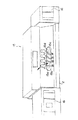
以下、図面を参照して本発明の好ましい実施形態について説明する。本発明に係る作業車の一例である高所作業車1を図2に示している。この高所作業車1は、車体2の前部に運転キャビン2aを有し、この運転キャビン2aの下部と車体2の後部には左右方向に配置された左右一対の前輪3aと左右一対の後輪3bが設けられている。これら一対の前輪3aは回転自在であり、一対の後輪3bは運転キャビン2a内に設けられた駐車ブレーキレバー13の作動により制動可能に設けられている。この駐車ブレーキレバー13は運転者により操作され、この駐車ブレーキレバー13の操作により後輪3bのみが制動されるが、一旦操作がなされるとこれが解除されない限り制動状態のまま保持される。
Hereinafter, preferred embodiments of the present invention will be described with reference to the drawings. FIG. 2 shows an
また、左右の前輪3aの後側に左前ジャッキ10aおよび右前ジャッキ(図示せず)が配設され、左右の後輪3bの後側に左後ジャッキ10bおよび右後ジャッキ10dが配設されている。左前ジャッキ10aには左前ジャッキシリンダ11aが、右前ジャッキには右前ジャッキシリンダ11c(図1を参照)が、左後ジャッキ10bには左後ジャッキシリンダ11bが、そして右後ジャッキ10dには右後ジャッキシリンダ11dがそれぞれ内蔵されており、これらのジャッキシリンダ11a,11b,11c,11dが伸縮動すると前後左右のジャッキ10a,10b,10dがそれぞれ伸縮動するように構成されている。なお、左前ジャッキ10aと、右前ジャッキと、左後ジャッキ10bと、右後ジャッキ10dは、本発明に係る複数のジャッキとなっている。
Also, a left front jack 10a and a right front jack (not shown) are disposed on the rear side of the left and right
車体2の上に図示しない旋回モータ(油圧モータ)により駆動されて、水平旋回可能に構成された旋回台4が配設されている。この旋回台4に基端部が枢結されてブーム5が取り付けられており、このブーム5は起伏シリンダ6により起伏動されるようになっている。ブーム5は、基端ブーム5a、中間ブーム5bおよび先端ブーム5cを入れ子式に組み合わせて、内蔵の伸縮シリンダ7により伸縮動可能に構成されている。
On the vehicle body 2, a
先端ブーム5cは先端にブームヘッド5dを有し、このブームヘッド5dに枢結されて支持部材8が上下に揺動可能に取り付けられている。この支持部材8は垂直ポスト部(図示せず)を有し、ブームヘッド5dと支持部材8との間に配設されたレベリングシリンダ(図示せず)により支持部材8の揺動制御が行われ、ブーム5の起伏如何に係わらず垂直ポスト部が常に垂直に延びて位置するように支持部材8が揺動制御される。このように常時垂直に保持される垂直ポスト部に水平旋回自在に(首振り自在に)作業台9が取り付けられており、作業台9はブーム5の起伏に係わらず常に水平に保持される。
The
上述した起伏シリンダ6と、伸縮シリンダ7と、左前ジャッキシリンダ11aと、右前ジャッキシリンダ11cと、左後ジャッキシリンダ11bと、右後ジャッキシリンダ11dは、油圧を利用して駆動されるため、車体2の前部には、エンジンE(図1を参照)からその出力(回転駆動力)の一部を取り出して油圧ポンプPを駆動するパワーテイクオフ機構PTO(図1を参照)が取り付けられている。すなわち、エンジンEの回転駆動力を利用して前ジャッキ10aおよび後ジャッキ10b,10dが伸縮動し、同様にして、ブーム5が起伏動および伸縮動するようになっている。
The hoisting cylinder 6, the
また、このパワーテイクオフ機構PTOをオン・オフ作動させる、すなわち油圧ポンプPを駆動させたり停止させるためのパワーテイクオフスイッチ14(図1を参照)が運転キャビン2a内の運転席に設けられている。なお、パワーテイクオフスイッチ14は、本発明におけるパワーテイクオフ作動手段となっている。 Further, a power take-off switch 14 (see FIG. 1) for turning on / off the power take-off mechanism PTO, that is, driving or stopping the hydraulic pump P, is provided in the driver's seat in the driving cabin 2a. The power take-off switch 14 is a power take-off actuating means in the present invention.
さて、前後左右のジャッキ10a,10b,10dの作動を手動操作するジャッキ操作装置15が車体2の後端に設けられている。ジャッキ操作装置15は、図3に示すように、車体2の後端に配設された一対のテールランプ16の間に配設されており、操作用の4本の操作レバー15a,15b,15c,15dを有している。すなわち、ジャッキ操作装置15は、左側から、左前ジャッキ10aを操作する左前操作レバー15aと、左後ジャッキ10bを操作する左後操作レバー15bと、右前ジャッキ(図示せず)を操作する右前操作レバー15cと、右後ジャッキ10dを操作する右後操作レバー15dとを有して構成されている。
A
各操作レバー15a,15b,15c,15dは車体2の前後方向に傾動自在であり、前側に傾動操作すると対応するジャッキが伸長動し、後側に傾動操作すると対応するジャッキが縮小動するように構成されている。また、各操作レバー15a,15b,15c,15dが非操作状態にあるときは垂直中立位置に自動復帰するように構成されている。なお、ジャッキ操作装置15は、本発明におけるジャッキ操作手段となっている。
The operation levers 15a, 15b, 15c, and 15d are tiltable in the front-rear direction of the vehicle body 2, and the corresponding jack expands when tilted to the front, and the corresponding jack contracts when tilted to the rear. It is configured. Further, when each operation lever 15a, 15b, 15c, 15d is in a non-operation state, it is configured to automatically return to the vertical neutral position. The
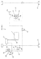
次に、高所作業車1のブレーキシステムについて図4を参照しながら説明する。このブレーキシステムは、前述の駐車ブレーキレバー13の操作により後輪3bを制動する駐車ブレーキ(図示せず)と、前輪3aおよび後輪3bをともに制動可能な主制動装置20と、本発明における補助制動装置である駐車補助装置50とを主体に構成される。主制動装置20は、前輪3aを制動可能なフロントホイールブレーキ21と、後輪3bを制動可能なリヤホイールブレーキ22と、運転キャビン2a内に設けられたブレーキペダル23と、ブレーキペダル23の踏み込み操作を補助するブレーキブースター24と、各ホイールブレーキ21,22にブレーキ液を供給するブレーキフルードタンク25と、ブレーキペダル23の踏み込み量(操作量)に応じてブレーキ液を加圧する(ブレーキ圧を発生させる)ブレーキマスターシリンダ26とを主体に構成される。
Next, the brake system of the
ブレーキブースター24には、バキュームタンク27およびエンジンEに駆動されるバキュームポンプ28が連結されており、バキュームタンク27およびバキュームポンプ28を利用してブレーキブースター24内に所定の負圧を発生させることで、ブレーキペダル23の踏み込み時に、その踏み込み力よりも大きな力をブレーキマスターシリンダ26に作用させることができるようになっている。また、ブレーキマスターシリンダ26とリヤホイールブレーキ22とを繋ぐ管路32には、車両(積載)重量に応じてブレーキ圧を制御するロードセンシングバルブ29が設けられている。
A
このように構成される主制動装置20において、ブレーキペダル23を踏み込むと、ブレーキマスターシリンダ26とフロントホイールブレーキ21とを繋ぐ管路31およびリヤホイールブレーキ22とを繋ぐ管路32内において、ブレーキマスターシリンダ26によりブレーキペダル23の踏み込み量(操作量)に応じてブレーキ液が加圧され、ブレーキ圧が発生する。そして、このブレーキ圧を利用してフロントホイールブレーキ21およびリヤホイールブレーキ22が作動し、前輪3aおよび後輪3bが制動される。
In the
なお、管路31にはフロントブレーキコントロールバルブ41と第1圧力スイッチ43とが設けられ、管路32にはリヤブレーキコントロールバルブ42が設けられており、主制動装置20の構成にこれらを加えて作業用制動装置40が構成される。この作業用制動装置40は、運転キャビン2a内に設けられた作業用制動装置作動スイッチ(図示せず)を押しながら、ブレーキペダル23を踏み込むことにより作動し、第1圧力スイッチ43に検出されるブレーキ液の圧力が所定圧になると、各ブレーキコントロールバルブ41,42が作動して管路31,32を塞ぎ、各ホイールブレーキ21,22のブレーキ圧が保持されて前輪3aおよび後輪3bが制動されるようになっている。なお、この状態で再び作業用制動装置作動スイッチを押すことにより、各ブレーキコントロールバルブ41,42の作動(すなわち、作業用制動装置40の作動)が解除され、主制動装置20が使用できるようになっている。
The
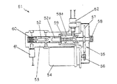
駐車補助装置50は、主制動装置20の構成に、管路32に設けられたブレーキアクチュエータ51を加えた構成となっている。ブレーキアクチュエータ51は、図5に示すように、ピストン52と、ピストン52が往復移動自在に収容され、フロントおよびリヤホイールブレーキ21,22に繋がるピストン収容部53と、電気モータ54と、電気モータ54の回転力をピストンの推進力に変換しピストンへ伝達する駆動力伝達部55とを主体に構成される。なお、フロントホイールブレーキ21とピストン収容部53とを繋ぐ管路は、図4において図示省略されている。
The
ピストン52は、ピストン収容部53内の一端側に往復移動自在に収容され、ピストン52がピストン収容部53の一端側に移動することにより、ブレーキ液を加圧できるようになっている。ピストン52の他端には逃げ穴52aが形成されており、駆動力伝達部55のボルト58と干渉しないようになっている。
The
駆動力伝達部55は、電気モータ54にギヤ56,57を介して回転駆動されるボルト58と、ボルト58と螺合(右ネジとする)してピストン52に隣接するナット59とを主体に構成され、ピストン収容部53内の他端側に配設される。ピストン収容部53の他端側(内側)には、ナット59の形状に合わせたナット収容部53aが形成されており、ナット59が回転することなくスライド移動可能に収容される。これにより、ナット59は、ボルト58の回転に伴ってナット収容部53a内を回転せずにスライド移動することができ、(駆動力伝達部55によって)電気モータ54の回転力をピストン52の推進力に変換しピストン52へ伝達することができる。
The driving
また、ピストン52とピストン収容部53との間隙部にはスプリング60が配設されており、ピストン52をピストン収容部53内の他端側へ移動させる方向に付勢するようになっている。さらに、ピストン収容部53の一端側には、ブレーキ液の圧力を検出する第2圧力スイッチ61が配設されており、ピストン収容部53の他端側には、ナット59を検出するリミットスイッチ62が設けられている。
Further, a
このように構成される駐車補助装置50において、コントローラ(詳細は後述する)からの制動作動信号を受けて電気モータ54が正転(図5および図6の左方から見て時計回りに回転)すると、ボルト58の回転に伴ってナット59がピストン収容部53の一端側へスライド移動する。そうすると、図6に示すように、ピストン52がナット59に押圧され、スプリング60の付勢力に抗してピストン収容部53の一端側へスライド移動し、ブレーキ液を加圧してブレーキ圧を発生させる。
In the parking assist
そして、このブレーキ圧を利用してフロントホイールブレーキ21およびリヤホイールブレーキ22が作動し、第2圧力スイッチ61に検出されるブレーキ液の圧力が所定圧になると、電気モータ54の回転が停止するとともにピストン52が駆動力伝達部55により停止位置で固定保持され、各ホイールブレーキ21,22のブレーキ圧が保持されて前輪3aおよび後輪3bが制動される。これにより、エンジンEの作動に拘わらず電力の供給だけで駐車補助装置50を作動させることができるため、高所作業車1の安全性をより向上させることができる。
When the
一方、図6に示すような駐車補助装置50の作動状態において、コントローラ(詳細は後述する)からの制動解除信号を受けて電気モータ54が逆転(図5および図6の左方から見て反時計回りに回転)すると、ボルト58の回転に伴ってナット59がピストン収容部53の他端側へスライド移動する。そうすると、ピストン52がスプリング60の付勢力を受けてピストン収容部53の他端側へスライド移動し、ブレーキ液の圧力が減圧される。そして、図5に示すように、ナット59がリミットスイッチ62に検出されるまでスライド移動すると、電気モータ54の回転が停止するとともにピストン52が駆動力伝達部55により停止位置で固定保持され、前輪3aおよび後輪3bの制動が解除されて主制動装置20を使用できるようになる。
On the other hand, in the operating state of the parking assist
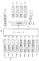
続いて、このような駐車補助装置50の作動を制御する高所作業車1の制御システムについて図1を参照しながら説明する。この制御システムは、コントローラ80からの制御信号により、駐車補助装置50の作動と、ジャッキ作動制御バルブ81の作動とを行うように構成されている。なお、コントローラ80は、ブームアクチュエータ(図示せず)等の作動も制御するが、説明を省略する。
Next, a control system for the
コントローラ80には、ジャッキ操作装置15からの操作信号、すなわち、左前操作レバー15aからの操作信号と、左後操作レバー15bからの操作信号と、右前操作レバー15cからの操作信号と、右後操作レバー15dからの操作信号とが入力される。なお、これからわかるように、コントローラ80は、各操作レバー15a,15b,15c,15d(ジャッキ操作装置15)が操作されたか否かを検出するジャッキ操作検出手段としての機能を有している。また、コントローラ80には、左前ジャッキ接地検出器82aからの接地信号と、左後ジャッキ接地検出器82bからの接地信号と、右前ジャッキ接地検出器82cからの接地信号と、右後ジャッキ接地検出器82dからの接地信号と、パワーテイクオフスイッチ14からの作動信号とが入力される。
The
左前操作レバー15a、左後操作レバー15b、右前操作レバー15c、そして右後操作レバー15dは、前側に傾動操作されるとジャッキ伸長操作信号を出力し、後側に傾動操作されるとジャッキ縮小操作信号を出力する。左前ジャッキ接地検出器82a、左後ジャッキ接地検出器82b、右前ジャッキ接地検出器82c、そして右後ジャッキ接地検出器82dは、左前ジャッキ10a、右前ジャッキ(図示せず)、左後ジャッキ10b、そして右後ジャッキ10dにそれぞれ設けられており、各ジャッキの下端部が地面に当接した(以下、これを「接地した」と称する)ときにそれぞれ接地信号を出力する。なお、左前ジャッキ接地検出器82a、左後ジャッキ接地検出器82b、右前ジャッキ接地検出器82c、そして右後ジャッキ接地検出器82dは、本発明におけるジャッキ接地検出手段となっている。
The left
パワーテイクオフスイッチ14は、パワーテイクオフ機構PTOのオン作動操作が行われるとオン作動信号を出力し、パワーテイクオフ機構PTOのオフ作動操作が行われるとオフ作動信号を出力する。また、ジャッキ作動制御バルブ81は、エンジンEによりパワーテイクオフ機構PTOを介して駆動される油圧ポンプPから各ジャッキシリンダ11a,11b,11c,11dへ供給される作動油の油路を、それぞれ開放または遮断する。
The power take-off switch 14 outputs an on-operation signal when the on-operation of the power take-off mechanism PTO is performed, and outputs an off-operation signal when the off-operation of the power take-off mechanism PTO is performed. The jack
以上のように構成される高所作業車1の制御システムにおいて、コントローラ80に全ての操作レバー15a,15b,15c,15dから操作信号が入力されない(又は、パワーテイクオフスイッチ14からオフ作動信号が入力される)場合には、コントローラ80はジャッキ作動制御バルブ81にジャッキ作動信号を出力せず、各ジャッキシリンダ11a,11b,11c,11dの作動は行われない。すなわち、全ての操作レバー15a,15b,15c,15d(ジャッキ操作装置15)が操作されない場合には、全てのジャッキシリンダ11a,11b,11c,11dは伸縮動を行わない。
In the control system for an
そして、駐車ブレーキ(図示せず)が作動した状態で、コントローラ80に、各操作レバー15a,15b,15c,15dの少なくとも一つから操作信号が入力され、且つパワーテイクオフスイッチ14からオン作動信号が入力されている場合には、コントローラ80はジャッキ作動制御バルブ81にジャッキ作動信号を出力し、(前側もしくは後側に)傾動操作された操作レバーに対応するジャッキシリンダの作動(伸長動もしくは縮小動)を行う制御を行う。すなわち、各操作レバー15a,15b,15c,15d(ジャッキ操作装置15)の少なくとも一つが操作された場合には、(前側もしくは後側に)傾動操作された操作レバーに対応するジャッキシリンダは、操作レバーの傾動方向に対応して伸縮動を行う。
Then, in a state where the parking brake (not shown) is activated, an operation signal is input to the
また、コントローラ80に、全てのジャッキ接地検出器82a,82b,82c,82dから接地信号が入力されず、且つ全ての操作レバー15a,15b,15c,15dから操作信号が入力されない(又は、パワーテイクオフスイッチ14からオフ作動信号が入力される)場合には、コントローラ80は駐車補助装置50に制動作動信号を出力せず、駐車補助装置50は制動作動を行わない。すなわち、全てのジャッキの下端部が非接地状態でジャッキ操作が行われない場合には、駐車補助装置50は作動せず、前後輪の制動に主制動装置20(あるいは駐車ブレーキ)が使用される。
In addition, the
そして、コントローラ80に、全てのジャッキ接地検出器82a,82b,82c,82dから接地信号が入力されず、且つパワーテイクオフスイッチ14からオン作動信号が入力されるとともに各操作レバー15a,15b,15c,15dの少なくとも一つから操作信号が入力される場合には、コントローラ80は駐車補助装置50に制動作動信号を出力し、駐車補助装置50が制動作動を行うように制御する。すなわち、各ジャッキ接地検出器82a,82b,82c,82dにより全てのジャッキの下端部が非接地状態であることが検出されており、且つパワーテイクオフスイッチ14からオン作動信号が入力されるとともに(ジャッキ操作検出手段としての)コントローラ80により各操作レバー15a,15b,15c,15dの少なくとも一つが操作されたことが検出された場合には、前輪3aおよび後輪3bをともに制動するように駐車補助装置50の作動を制御する。
The
一方、各ジャッキ接地検出器82a,82b,82c,82dの少なくとも一つから接地信号がコントローラ80に入力される場合には、コントローラ80は駐車補助装置50に制動作動信号を出力し、駐車補助装置50が制動作動を行うように制御する。すなわち、各ジャッキ接地検出器82a,82b,82c,82dにより前後左右のジャッキの下端部における少なくとも一つが地面に当接したことが検出されている場合には、パワーテイクオフスイッチ14およびジャッキ操作装置15の操作に拘わらず、前輪3aおよび後輪3bをともに制動するように駐車補助装置50の作動を制御する。
On the other hand, when a ground signal is input to the
なお、上述のように前後輪をともに制動するように駐車補助装置50が作動した状態において、コントローラ80に、全てのジャッキ接地検出器82a,82b,82c,82dから接地信号が入力されず、且つ全ての操作レバー15a,15b,15c,15dから操作信号が入力されない場合には、コントローラ80は駐車補助装置50に制動解除信号を出力し、駐車補助装置50が前後輪の制動を解除する作動を行うように制御する。すなわち、各ジャッキ接地検出器82a,82b,82c,82dにより全てのジャッキの下端部が非接地状態であることが検出されており、且つ(ジャッキ操作検出手段としての)コントローラ80により全ての操作レバー15a,15b,15c,15d(ジャッキ操作装置15)が非操作状態であることが検出された場合には、前輪3aおよび後輪3bに対する制動を解除するように駐車補助装置50の作動を制御する。
In the state where the parking assist
これにより、ジャッキが一つでも接地した状態では前後輪全てにおいて制動力が確保されるので、車両が勝手に移動してしまうことをより確実に防止することができ、ジャッキ作業における安全性を向上させることができる。また、ジャッキが接地するまでは、ジャッキ操作を停止すると駐車補助装置50による前後輪の制動が解除されるため、ジャッキが接地しない範囲で伸長する状態においても、車両を若干量移動させることが可能となり、ジャッキ作業における作業効率を向上させることができる。さらに、ジャッキ接地検出器はジャッキに標準取り付けされることが多いため、製造コストの大幅な上昇を招かずに、ジャッキ作業における安全性を向上させることができる。
As a result, the braking force is secured in all front and rear wheels when one jack is in contact with the ground, so it is possible to more reliably prevent the vehicle from moving without permission and improve the safety in jacking. Can be made. Further, when the jack operation is stopped until the jack is grounded, the braking of the front and rear wheels by the parking assist
以上のような構成の高所作業車1によれば、コントローラ80が、各ジャッキ接地検出器82a,82b,82c,82dにより前後左右の(複数の)ジャッキの下端部における少なくとも一つが地面に当接したことが検出されている場合には、前輪3aおよび後輪3bをともに制動するように駐車補助装置50の作動を制御するため、パワーテイクオフスイッチ14およびジャッキ操作装置15の操作に拘わらず、ジャッキが一つでも接地した状態では前後輪全てにおいて制動力が確保されるので、車両が勝手に移動してしまうことをより確実に防止することができ、ジャッキ作業における安全性を向上させることができる。
According to the
また、コントローラ80が、各ジャッキ接地検出器82a,82b,82c,82dにより全てのジャッキの下端部が非接地状態であることが検出されており、且つ(ジャッキ操作検出手段としての)コントローラ80によりジャッキ操作装置15が非操作状態であることが検出された場合には、前輪3aおよび後輪3bに対する制動を解除するように駐車補助装置50の作動を制御するため、同様に、ジャッキが一つでも接地した状態では前後輪全てにおいて制動力が確保されるので、車両が勝手に移動してしまうことをより確実に防止することができ、ジャッキ作業における安全性を向上させることができる。
Further, the
なお、上述の実施形態において、本発明に係る作業車として高所作業車1を例に説明したが、これに限られるものではなく、例えば、クレーン車や穴掘り建柱車等、前輪および後輪を有して走行可能な車体に、これら前後輪に隣接して車体を持ち上げ支持する複数のジャッキを備えた作業車であれば、本発明を適用することができる。
In the above-described embodiment, the
また、上述の実施形態において、本発明における補助制動装置として駐車補助装置50
を用いているが、これに限られるものではなく、作業用制動装置40を利用するようにしてもよい。なお、作業用制動装置40を利用する場合、コントローラからの制御信号に応じてブレーキペダル23を駆動する(揺動操作させる)ブレーキペダル駆動手段が必要である。
In the above-described embodiment, the parking assist
However, the present invention is not limited to this, and the
さらに、上述の実施形態において、ジャッキが接地したか否かに応じて駐車補助装置50の作動を制御しているが、これに限られるものではなく、前輪および後輪に作用する荷重の変化(前輪および後輪に作用する荷重が所定荷重以下の場合に車体が浮くと判断する)に応じて駐車補助装置50の作動を制御するようにしてもよい。
Furthermore, in the above-described embodiment, the operation of the parking assist
また、ジャッキが格納状態にあるか否かを検出するジャッキ格納検出器を用いて、コントローラが、ジャッキ格納検出器により全てのジャッキが格納状態であることが検出されている場合には、前輪および後輪の制動を解除するように駐車補助装置(補助制動装置)の作動を制御し、ジャッキ格納検出器によりの全てのジャッキにおける少なくとも一つが非格納状態であることが検出されている場合には、前輪および後輪をともに制動するように駐車補助装置(補助制動装置)の作動を制御するようにしてもよい。このようにすれば、誤ってジャッキを伸長させたまま車両が移動することを防止することができる。 In addition, when the jack storage detector that detects whether or not the jack is in the retracted state and the controller detects that all jacks are in the retracted state by the jack storage detector, the front wheel and When the operation of the parking auxiliary device (auxiliary braking device) is controlled so as to release the braking of the rear wheel, and it is detected that at least one of all jacks by the jack storage detector is in the non-retracted state The operation of the parking assist device (auxiliary braking device) may be controlled so as to brake both the front wheels and the rear wheels. In this way, it is possible to prevent the vehicle from moving while the jack is accidentally extended.
さらに、上述の実施形態において、本発明におけるジャッキ操作検出手段としてジャッキ操作装置15からの操作信号が入力されるコントローラ80を用いているが、これに限られるものではなく、例えば、各操作レバー(ジャッキ操作装置)の動きを検出するスイッチ(リミットスイッチ等)や、操作レバーに繋がるバルブスプールの先端部の動きを検出するスイッチでもよく、ジャッキ操作装置(手段)が操作されたか否かを検出可能であればよい。
Furthermore, in the above-described embodiment, the
1 高所作業車
2 車体(2a 運転キャビン)
3a 前輪
3b 後輪
10a 左前ジャッキ
10b 左後ジャッキ
10d 右後ジャッキ
14 パワーテイクオフスイッチ(パワーテイクオフ作動手段)
15 ジャッキ操作装置(ジャッキ操作手段)
20 主制動装置
40 作業用制動装置
50 駐車補助装置(補助制動装置)
80 コントローラ
82a 左前ジャッキ接地検出器(ジャッキ接地検出手段)
82b 左後ジャッキ接地検出器(ジャッキ接地検出手段)
82c 右前ジャッキ接地検出器(ジャッキ接地検出手段)
82d 右後ジャッキ接地検出器(ジャッキ接地検出手段)
E エンジン
PTO パワーテイクオフ機構
1 High-altitude work vehicle 2 Car body (2a Driving cabin)
3a front wheel 3b rear wheel 10a left front jack 10b left
15 Jack operation device (jack operation means)
20
80 Controller 82a Left front jack ground detector (jack ground detection means)
82b Left rear jack ground detector (jack ground detection means)
82c Right front jack ground detector (jack ground detection means)
82d Right rear jack ground detector (jack ground detection means)
E engine PTO power take-off mechanism
Claims (2)
前記前輪および前記後輪にそれぞれ隣接して設けられ、前記エンジンの前記回転駆動力を用いて作動し前記車体を持ち上げ支持する複数のジャッキと、
前記エンジンの前記回転駆動力を前記ジャッキ側に取り出すパワーテイクオフ機構と、
前記パワーテイクオフ機構をオン・オフ作動させるための操作をするパワーテイクオフ作動手段と、
前記複数のジャッキの操作を行うジャッキ操作手段と、
前記複数のジャッキの下端部が地面に当接したか否かをそれぞれ検出するジャッキ接地検出手段と、
前記ジャッキ操作手段が操作されたか否かを検出するジャッキ操作検出手段と、
前記前輪および前記後輪をともに制動する補助制動装置と、
前記ジャッキ接地検出手段により全ての前記ジャッキの下端部が非接地状態であることが検出されており、且つ前記パワーテイクオフ作動手段からオン作動信号が入力されるとともに前記ジャッキ操作検出手段により前記ジャッキ操作手段が操作されたことが検出された場合には、前記前輪および前記後輪をともに制動させるように前記補助制動装置の作動を制御し、前記ジャッキ接地検出手段により前記複数のジャッキの下端部における少なくとも一つが地面に当接したことが検出されている場合には、前記前輪および前記後輪をともに制動するように前記補助制動装置の作動を制御するコントローラとを備えて構成されることを特徴とする作業車。 A vehicle body having front and rear wheels and capable of traveling using the rotational driving force of the engine;
A plurality of jacks provided adjacent to the front wheel and the rear wheel, respectively, that operate using the rotational driving force of the engine to lift and support the vehicle body;
A power take-off mechanism for extracting the rotational driving force of the engine to the jack side;
Power take-off actuating means for operating the power take-off mechanism to turn on / off;
Jack operating means for operating the plurality of jacks;
Jack grounding detection means for detecting whether or not lower end portions of the plurality of jacks are in contact with the ground;
Jack operation detecting means for detecting whether or not the jack operating means has been operated;
An auxiliary braking device for braking both the front wheel and the rear wheel;
It is detected by the jack ground detection means that the lower end portions of all the jacks are not grounded, and an ON operation signal is input from the power take-off operation means, and the jack operation detection means performs the jack operation. When it is detected that the means is operated, the operation of the auxiliary braking device is controlled so as to brake both the front wheel and the rear wheel, and the jack grounding detecting means controls the lower end portions of the plurality of jacks. And a controller for controlling the operation of the auxiliary braking device so as to brake both the front wheel and the rear wheel when it is detected that at least one of the wheels touches the ground. Work vehicle.
前記前輪および前記後輪にそれぞれ隣接して設けられて前記車体を持ち上げ支持する複数のジャッキと、
前記複数のジャッキの操作を行うジャッキ操作手段と、
前記複数のジャッキの下端部が地面に当接したか否かをそれぞれ検出するジャッキ接地検出手段と、
前記ジャッキ操作手段が操作されたか否かを検出するジャッキ操作検出手段と、
前記前輪および前記後輪をともに制動する補助制動装置と、
前記ジャッキ接地検出手段により前記複数のジャッキの下端部における少なくとも一つが地面に当接したことが検出されている場合には、前記前輪および前記後輪をともに制動するように前記補助制動装置の作動を制御し、前記ジャッキ接地検出手段により全ての前記ジャッキの下端部が非接地状態であることが検出されており、且つ前記ジャッキ操作検出手段により前記ジャッキ操作手段が非操作状態であることが検出された場合には、前記前輪および前記後輪に対する制動を解除するように前記補助制動装置の作動を制御するコントローラとを備えて構成されることを特徴とする作業車。 A vehicle body capable of traveling with front and rear wheels;
A plurality of jacks provided adjacent to the front wheel and the rear wheel to lift and support the vehicle body;
Jack operating means for operating the plurality of jacks;
Jack grounding detection means for detecting whether or not lower end portions of the plurality of jacks are in contact with the ground;
Jack operation detecting means for detecting whether or not the jack operating means has been operated;
An auxiliary braking device for braking both the front wheel and the rear wheel;
When the jack contact detection means detects that at least one of lower end portions of the plurality of jacks is in contact with the ground, the auxiliary braking device is actuated to brake both the front wheel and the rear wheel. The jack grounding detecting means detects that the lower end portions of all the jacks are in a non-grounded state, and the jack operation detecting means detects that the jack operating means is in a non-operating state. And a controller for controlling the operation of the auxiliary braking device so as to release the braking on the front wheels and the rear wheels.
Priority Applications (1)
| Application Number | Priority Date | Filing Date | Title |
|---|---|---|---|
| JP2003376455A JP2005138946A (en) | 2003-11-06 | 2003-11-06 | Work vehicle |
Applications Claiming Priority (1)
| Application Number | Priority Date | Filing Date | Title |
|---|---|---|---|
| JP2003376455A JP2005138946A (en) | 2003-11-06 | 2003-11-06 | Work vehicle |
Publications (2)
| Publication Number | Publication Date |
|---|---|
| JP2005138946A true JP2005138946A (en) | 2005-06-02 |
| JP2005138946A5 JP2005138946A5 (en) | 2006-10-05 |
Family
ID=34687489
Family Applications (1)
| Application Number | Title | Priority Date | Filing Date |
|---|---|---|---|
| JP2003376455A Pending JP2005138946A (en) | 2003-11-06 | 2003-11-06 | Work vehicle |
Country Status (1)
| Country | Link |
|---|---|
| JP (1) | JP2005138946A (en) |
Cited By (1)
| Publication number | Priority date | Publication date | Assignee | Title |
|---|---|---|---|---|
| JP2011032019A (en) * | 2009-07-31 | 2011-02-17 | Tadano Ltd | Working vehicle |
-
2003
- 2003-11-06 JP JP2003376455A patent/JP2005138946A/en active Pending
Cited By (1)
| Publication number | Priority date | Publication date | Assignee | Title |
|---|---|---|---|---|
| JP2011032019A (en) * | 2009-07-31 | 2011-02-17 | Tadano Ltd | Working vehicle |
Similar Documents
| Publication | Publication Date | Title |
|---|---|---|
| WO2001094147A1 (en) | Method and device for controlling specific functions within a load-carrying vehicle under dumping and/or loading the load-carrying platform of the vehicle | |
| AU2020200594B2 (en) | Mobile crane, mobile crane dolly and mobile crane system | |
| JP2005138946A (en) | Work vehicle | |
| JP2017177904A (en) | Brake equipment of high-lift work vehicle | |
| JP7384135B2 (en) | Automatic braking devices for industrial vehicles and industrial vehicles | |
| JP2014201442A (en) | Vehicle for high lift work | |
| US6029779A (en) | Automatic parking brake and steering spindle | |
| JP4430978B2 (en) | Work vehicle | |
| JP2005022787A (en) | Safety device for equipment-mounted working vehicle | |
| JPH0626554Y2 (en) | Safety equipment for work vehicles | |
| JP2014151991A (en) | High lift work vehicle | |
| JPH0626458Y2 (en) | Safety equipment for work vehicles | |
| JP4243438B2 (en) | Jack control device for work vehicle | |
| KR0134953Y1 (en) | Auxiliary brake device of a fork lift | |
| JP3693536B2 (en) | Work vehicle operation restriction device | |
| JP2003095599A (en) | Safety device of work vehicle | |
| JP2605527Y2 (en) | Work vehicle parking brake control device | |
| JP2001341996A (en) | Jack operation control device for working vehicle | |
| JP2016137873A (en) | Work vehicle | |
| JP2003192300A (en) | Safety device of work vehicle | |
| JPH1120536A (en) | Remote operation device for carriage | |
| JP2022162621A (en) | Working vehicle | |
| JP2592630Y2 (en) | Emergency braking device for mobile cranes | |
| JP2541693Y2 (en) | Free running device for hydraulic traveling vehicles | |
| JPH0620798Y2 (en) | Safety equipment for aerial work vehicles |
Legal Events
| Date | Code | Title | Description |
|---|---|---|---|
| A521 | Written amendment |
Effective date: 20060822 Free format text: JAPANESE INTERMEDIATE CODE: A523 |
|
| A621 | Written request for application examination |
Free format text: JAPANESE INTERMEDIATE CODE: A621 Effective date: 20060822 |
|
| A977 | Report on retrieval |
Free format text: JAPANESE INTERMEDIATE CODE: A971007 Effective date: 20090518 |
|
| A131 | Notification of reasons for refusal |
Free format text: JAPANESE INTERMEDIATE CODE: A131 Effective date: 20090612 |
|
| A02 | Decision of refusal |
Free format text: JAPANESE INTERMEDIATE CODE: A02 Effective date: 20091016 |