JP2005124576A - Device for separating tobacco and transport air and structure and method for forming at least two tobacco rods in endless rod maker - Google Patents
Device for separating tobacco and transport air and structure and method for forming at least two tobacco rods in endless rod maker Download PDFInfo
- Publication number
- JP2005124576A JP2005124576A JP2004310737A JP2004310737A JP2005124576A JP 2005124576 A JP2005124576 A JP 2005124576A JP 2004310737 A JP2004310737 A JP 2004310737A JP 2004310737 A JP2004310737 A JP 2004310737A JP 2005124576 A JP2005124576 A JP 2005124576A
- Authority
- JP
- Japan
- Prior art keywords
- tobacco
- cigarette
- air
- weir
- duct
- Prior art date
- Legal status (The legal status is an assumption and is not a legal conclusion. Google has not performed a legal analysis and makes no representation as to the accuracy of the status listed.)
- Withdrawn
Links
Images


Classifications
-
- A—HUMAN NECESSITIES
- A24—TOBACCO; CIGARS; CIGARETTES; SIMULATED SMOKING DEVICES; SMOKERS' REQUISITES
- A24C—MACHINES FOR MAKING CIGARS OR CIGARETTES
- A24C5/00—Making cigarettes; Making tipping materials for, or attaching filters or mouthpieces to, cigars or cigarettes
- A24C5/14—Machines of the continuous-rod type
- A24C5/18—Forming the rod
- A24C5/1835—Multiple rod making devices
Abstract
Description
本発明は、たばこと搬送空気を分離する装置並びに紙巻きたばこ連続体製造機械で少なくとも2つのたばこ連続体を形成する構造体に関する。 The present invention relates to an apparatus for separating tobacco and carrier air and a structure for forming at least two tobacco continuums in a cigarette continuum manufacturing machine.
本発明は更に、紙巻きたばこ連続体製造機械と、1つのたばこ溜めから少なくとも2つのたばこ連続体を形成する方法に関する。 The invention further relates to a cigarette continuum manufacturing machine and a method of forming at least two cigarette continuums from one cigarette sump.
本出願人の特許文献1から、紙巻きたばこ連続体製造機械で少なくとも1つのたばこ連続体を形成する構造体が知られている。この特許文献1に記載された構造体の根底をなす課題は、たばこ供給手段を構造的および流れ技術的に最適に形成することにより、流動床分配器の作用を強めかつ安定化することである。そのために、紙巻きたばこ連続体製造機械で少なくとも1つのたばこ連続体を形成する構造体は、連続体サクションコンベヤに至る、たばこ/空気層を形成する流動面を案内する供給手段を備えている。この場合、供給手段は、たばこの搬送方向に関連して、流動面に開口する配量手段の上流側に設けられたふるい手段を備えている。この場合、ふるい手段は好ましくはジグザグふるいである。本発明の範囲内で、流動面は特にたばこと空気の層を形成するために設けられている。 From the applicant's patent document 1, a structure is known in which at least one cigarette continuum is formed in a cigarette continuum manufacturing machine. The problem underlying the structure described in Patent Document 1 is to strengthen and stabilize the action of the fluidized bed distributor by optimally forming the tobacco supply means in terms of structure and flow technology. . To that end, the structure forming at least one cigarette continuum in a cigarette continuum manufacturing machine comprises supply means for guiding the flow surface forming the cigarette / air layer leading to the continuum suction conveyor. In this case, the supply means includes sieving means provided on the upstream side of the metering means that opens to the flow surface in relation to the direction of cigarette transport. In this case, the sieving means is preferably a zigzag sieve. Within the scope of the invention, the flow surface is provided in particular to form a layer of tobacco and air.
更に、特許文献2により、たばこ堰止めダクトによって二重連続体製造機械にたばこを供給することが知られている。この場合、たばこ搬送方向において堰止めダクトの後方に、ふるいが配置されている。特許文献2の装置または構造体の場合、たばこは例えば特許文献2の図1に示された分配器の全幅(その長さは図3からよく判る)にわたって、案内面(本発明では流動面とも言う)上に形成される。この特許文献2の図2の矢視方向IIIの図から、案内面または流動面の幅が非常によく判る。この幅はたばこの移動方向に対して横方向に案内面または流動面全体にわたって延びている。特許文献2と特許文献1は内容全体がこの本願の開示内容に加えられる。特許文献2の案内面は本願では流動面と呼ばれる。 Furthermore, it is known from Patent Document 2 to supply tobacco to a double continuum manufacturing machine by a tobacco weir duct. In this case, a sieve is arranged behind the weir duct in the cigarette transport direction. In the case of the device or structure of Patent Document 2, the cigarette is, for example, a guide surface (in the present invention, a flow surface) over the entire width of the distributor shown in FIG. Say) formed on. The width of the guide surface or the flow surface can be seen very well from the view in the arrow direction III of FIG. This width extends across the entire guide surface or flow surface in a direction transverse to the direction of tobacco movement. The entire contents of Patent Document 2 and Patent Document 1 are added to the disclosure content of this application. The guide surface of Patent Document 2 is called a fluid surface in the present application.
公開されていない本出願人の特許文献3には、紙巻きたばこ連続体製造機械のたばこの加工速度を加速することができる構造体と方法が知られている。この場合、1つよりも多いたばこ連続体の場合に繊維長さ、混合および種類に関してたばこが均一に分配される。更に、変形によれば、連続体形成が構造体の全幅またはほぼ全幅にわたって可能であるので、きわめて迅速な連続体形成が実現可能である。これは上記の特許文献3(その内容全体が本願の開示内容に加えられる)において、紙巻きたばこ連続体製造機械において少なくとも2つのたばこ連続体を形成するための構造体が次の特徴を備えていることによって解決される。 Patent Document 3 of the present applicant, which has not been disclosed, discloses a structure and a method capable of accelerating the processing speed of cigarettes in a continuous cigarette manufacturing machine. In this case, the tobacco is evenly distributed in terms of fiber length, mixing and type in the case of more than one tobacco continuum. Furthermore, according to the modification, continuum formation is possible over the entire width or almost the entire width of the structure, so that very rapid continuum formation can be realized. In Patent Document 3 (the entire contents of which are added to the disclosure content of the present application), a structure for forming at least two cigarette continuums in a cigarette continuum manufacturing machine has the following characteristics. It is solved by.
特に配量および/またはふるいにかけたたばこを、少なくともそれぞれ連続体サクションコンベヤに至る少なくとも2つの流動面に搬送するための供給手段。この場合、供給手段は少なくとも2つの堰止めダクトを備えている。この堰止めダクトは連続体サクションコンベヤの搬送方向に対して横方向に並べて配置されている。同様に、1つのたばこ溜めから少なくとも2つのたばこ連続体を形成するための方法が開示されている。この場合、たばこ溜めかたばこが特に直接的に少なくとも2つの堰止めダクトに装入される。少なくとも2つの堰止めダクトからたばこはそれぞれ1つの流動面に搬送され、続いてたばこは少なくとも2つの連続体サクションコンベヤに供給される。堰止めダクトは連続体サクションコンベヤの搬送方向に対して横方向に並べて配置されている。
この技術水準に対して、本発明の課題は、特許文献3によって知られている構造体と、対応する公知の方法を、次のように形成することである。すなわち、構造体がコンパクトであり、方法の実施に関連して、1つよりも多いたばこ連続体の場合に繊維長さ、混合および種類に関してたばこが均一に分配されるように形成することである。 In contrast to this state of the art, the task of the present invention is to form the structure known from US Pat. That is, the structure is compact and in connection with the implementation of the method, in the case of more than one cigarette continuum, the cigarettes are formed so that they are evenly distributed in terms of fiber length, mixing and type. .
この課題は、たばこが装置の空気流に供給可能であり、かつ空気流から分離されて装置から搬出可能であり、たばこ案内壁が装置の少なくとも出口側で、たばこを少なくとも2個所で順々に送出するために動くことができるように形成されている、たばこ案内壁と分離要素とを備えた、たばこと搬送空気を分離するための装置によって解決される。すなわち、この手段により、例えば特許文献3の図1に参照数字39で示してある他の装入手段を省略することができ、その際連続体の製造時に品質を低下させることがない。これにより、他の装入手段を設けるために必要な高さを低くすることができる。
The problem is that the cigarette can be supplied to the airflow of the device and can be separated from the airflow and carried out of the device, the cigarette guide wall at least on the outlet side of the device and the cigarettes in at least two places one after the other. It is solved by a device for separating tobacco and carrier air, comprising a tobacco guide wall and a separating element, which are configured to be movable for delivery. That is, by this means, for example, the other charging means indicated by the
少なくとも2個所でのたばこの送出は好ましくは、たばこ装入スルースゲートの排出周波数よりも大きな、好ましくははるかに大きな周波数または装入周波数で行われる。相応して形成された、本発明による装置を有する構造体によって、たばこの混合物分解の準備が行われる。例えば装入周波数は堰止めダクトの排出周波数の10倍であるかまたは例えば5倍である。たばこ装入スルースゲートは予分配器の手前に配置され、一般的に空気圧で紙巻きたばこ製造機械に搬送されるきざみたばこを受け取る。このきざみたばこはたばこ準備装置(一次)で処理される。本発明に範囲内において、用語“動くことができる”は用語“摺動可能である”を含んでいる。 Tobacco delivery in at least two places is preferably performed at a frequency that is greater than the discharge frequency of the tobacco charging sluice gate, preferably much higher. A correspondingly formed structure with the device according to the invention prepares the tobacco mixture for decomposition. For example, the charging frequency is 10 times or for example 5 times the discharge frequency of the weir duct. The tobacco charging sluice gate is placed in front of the pre-distributor and receives chopped tobacco that is generally pneumatically transported to the cigarette making machine. This chopped tobacco is processed by a tobacco preparation device (primary). Within the scope of the present invention, the term “movable” includes the term “slidable”.
たばこ案内壁が凸形に形成されていると、空気流または搬送空気からたばこを分離するために遠心力を利用することができる。 If the tobacco guide wall is formed in a convex shape, centrifugal force can be used to separate the tobacco from the air flow or the carrier air.
たばこ案内壁は好ましくは少なくとも部分的に揺動可能に形成されている。本発明による装置のきわめて簡単な実施形では、たばこ案内壁の一部がフラップとして形成されている。フラップは、たばこを異なる場所に供給するために揺動させられる。フラップは好ましくは回転点回りに揺動可能である。たばこ案内壁が装置の出口側で、スルースゲートの案内壁に向きを揃えることが可能であると、たばこの混合物が分解しないように作用する。有利なスルースゲートは、残りの搬送空気から分離するためおよび/またはたばこを配量するために役立つロータリフィーダを備えている。 The tobacco guide wall is preferably at least partially pivotable. In a very simple embodiment of the device according to the invention, a part of the tobacco guide wall is formed as a flap. The flap is swung to supply the cigarette to different locations. The flap is preferably swingable about a rotation point. If the cigarette guide wall can be aligned with the guide wall of the sluice gate at the outlet side of the device, it acts to prevent the tobacco mixture from being decomposed. An advantageous sluice gate is equipped with a rotary feeder which serves to separate the remaining carrier air and / or to dispense tobacco.
課題は更に、特に配量されおよび/またはふるいにかけられたたばこを、少なくとも各々1個の連続体サクションコンベヤに至る少なくとも2つの流動面に搬送するための供給手段が設けられ、供給手段が少なくとも2個の堰止めダクトを備え、この堰止めダクトが連続体サクションコンベヤの搬送方向に対して横方向に並べて配置され、堰止めダクトの上流側に、上記の本発明による装置が配置されている、紙巻きたばこ連続体製造機械で少なくとも2つのたばこ連続体を形成するための構造体によって解決される。本発明による構造体は省スペース的である。すなわち、低い構造高さで実施可能である。更に、運転の信頼性がきわめて高い。というのは、たばこ落下区間をほぼ垂直に配置することができるからである。好ましくは、たばこと空気を分離するための装置と各々の堰止めダクトとの間に、たばこを分与するためおよび/または残留搬送空気を分離するための各々1個のスルースゲートが設けられている。 The problem is further provided with supply means for transporting specifically metered and / or sieved cigarettes to at least two flow surfaces each leading to at least one continuous suction conveyor, the supply means comprising at least 2 Comprising a plurality of damming ducts, the damming ducts are arranged side by side with respect to the conveying direction of the continuum suction conveyor, and the apparatus according to the present invention is arranged on the upstream side of the damming ducts, This is solved by a structure for forming at least two tobacco continuums in a cigarette continuum making machine. The structure according to the invention is space saving. That is, it can be implemented with a low structural height. Furthermore, the operation reliability is extremely high. This is because the tobacco falling section can be arranged almost vertically. Preferably, one sluice gate is provided between each device for separating tobacco and air and each damming duct for dispensing tobacco and / or separating residual carrier air. Yes.
課題は更に、特に配量されおよび/またはふるいにかけられたたばこを、少なくとも各々1個の連続体サクションコンベヤに至る流動面に搬送するための供給手段が設けられ、供給手段が少なくとも2個の堰止めダクトを備え、たばこを分与するためおよび/または残留搬送空気を分離するための各々1個のスルースゲートが少なくとも2個の堰止めダクトの手前に設けられ、たばこと空気を分離するために1個の装置からスルースゲートにたばこを供給可能である、紙巻きたばこ連続体製造機械で少なくとも2つのたばこ連続体を形成するための構造体によって解決される。 The problem is further provided with supply means for transporting specifically metered and / or sieved cigarettes to a flow surface each leading to at least one continuous suction conveyor, the supply means comprising at least two weirs. In order to separate tobacco and air, a stop duct is provided, each having a sluice gate for dispensing tobacco and / or for separating residual carrier air, in front of at least two weir ducts This is solved by a structure for forming at least two cigarette continuums on a cigarette continuum making machine that can supply cigarettes from a single device to a sluice gate.
本発明によるこの構造体によっても、低い構造高さが実現可能である。この場合、比較的に少ない機械要素が使用される。 Even with this structure according to the invention, a low structural height can be realized. In this case, relatively few machine elements are used.
好ましくは、たばこが堰止めダクトに交互に供給可能である。本発明による紙巻きたばこ連続体製造機械は、上述したような本発明による装置および/または上述したような本発明による構造体を備えている。 Preferably, cigarettes can be alternately supplied to the weir duct. The cigarette continuum making machine according to the invention comprises a device according to the invention as described above and / or a structure according to the invention as described above.
課題は更に、たばこがたばこ溜めから少なくとも2個の堰止めダクトに装入され、たばこが少なくとも2個の堰止めダクトからそれぞれ少なくとも1個の流動面に搬送され、続いてたばこが少なくとも2個の連続体サクションコンベヤに供給され、この場合たばこが空気流によって搬送され、堰止めダクトに搬送する前に、たばこと搬送空気を分離するための装置によって、たばこが空気流から分離され、たばこが、たばこと搬送空気を分離する装置から空気流を分離した直後、堰止めダクトに交互に供給される、1つのたばこ溜めから少なくとも2つのたばこ連続体を形成するための方法によって解決される。 The problem is further that tobacco is loaded from the tobacco reservoir into at least two weir ducts, tobacco is transported from at least two weir ducts to each at least one flow surface, followed by at least two cigarettes. The cigarette is separated from the air flow by means of a device for separating the cigarette and the conveying air before it is fed to the continuum suction conveyor, in which case the cigarette is conveyed by the air flow and conveyed to the weir duct, This is solved by a method for forming at least two cigarette continuum from one cigarette sump, which is fed alternately to the weir duct, immediately after separating the air flow from the apparatus for separating cigarette and carrier air.
これによって、少なくとも2つのたばこ連続体の確実な形成が可能である。この場合、異なるたばこ連続体へのたばこの均一な分配を実現可能である。たばこは常に所定の時間にのみ、それぞれ1つの堰止めダクトに供給され、続いて他の堰止めダクトに供給される。これは好ましくは順番にまたは交互に行われる。たばこを堰止めダクトに供給する前および空気流を分離した後で、たばこが先ず最初に各々1個のスルースゲートに交互に供給され、たばこがスルースゲートによって分与され、および/または残留搬送空気が分離されると、均一な連続体形成が可能である。好ましくは、各堰止めダクトのために、1個のスルースゲートが設けられている。特に有利な実施形では、堰止めダクトが連続体サクションコンベヤへのたばこの搬送方向に対して横方向に並べて配置されている。これによって、きわめて均一なたばこ連続体形成が可能である。 This makes it possible to reliably form at least two tobacco continuums. In this case, it is possible to achieve a uniform distribution of tobacco to different tobacco continuums. Tobacco is always fed to one dam duct only at a predetermined time and subsequently to the other dam duct. This is preferably done sequentially or alternately. Before feeding the cigarette to the weir duct and after separating the air flow, the cigarette is first fed alternately to each one sluice gate, the cigarette is dispensed by the sluice gate, and / or residual carrier air When these are separated, a uniform continuous body can be formed. Preferably, one sluice gate is provided for each dam duct. In a particularly advantageous embodiment, the weir ducts are arranged side by side with respect to the direction of transport of the tobacco to the continuum suction conveyor. This makes it possible to form an extremely uniform tobacco continuum.
合目的な方法実施では、堰止めダクトがほぼ構造体の全幅にわたって延びている。構造体の幅は本発明の範囲では特にたばこの全幅または流動面が他の流動面に分割される前の流動面の全幅である。本発明の範囲では、用語“ほぼ全幅”は全幅も含んでいる。この場合勿論、たばこ分配またはたばこ連続体形成のために設けられていない、構造体の周りに配置されたケーシングは、幅に数えられない。全幅はドイツ連邦共和国特許第3209195号の図4の範囲では、落下案内ダクト31内の壁36の全体幅である。換言すると、幅はたばこ形成のために使用される、構造体の有効幅である。
In a purposeful method implementation, the weir duct extends almost the entire width of the structure. The width of the structure is, in the scope of the present invention, in particular the full width of the cigarette or the full width of the flow surface before it is divided into other flow surfaces. Within the scope of the present invention, the term “substantially full width” includes full width as well. In this case, of course, casings arranged around the structure that are not provided for tobacco distribution or tobacco continuum formation do not count in width. The full width is the entire width of the
堰止めダクトが互いにほぼ平行であると、非常に均一なたばこ連続体を生じることができる。堰止めダクトは本発明の範囲では特に並べて配置されている。本発明の範囲内で“並べて”は特に幅に対して横方向に配置することを意味する。操作人が構造体の前に立ち、連続体サクションコンベヤがその観察時に左側から右側に(およびその逆に)延びていると、堰止めダクトは並べて設けられている。 If the weir ducts are substantially parallel to each other, a very uniform tobacco continuum can be produced. The dam ducts are particularly arranged side by side within the scope of the invention. Within the scope of the present invention, “side by side” means in particular the arrangement transverse to the width. When the operator stands in front of the structure and the continuum suction conveyor extends from the left side to the right side (and vice versa) during the observation, the dam ducts are provided side by side.
少なくとも1のたばこふるいが設けられ、この場合少なくとも1個のたばこふるいがたばこ流れに関して堰止めダクトの手前に配置されていると、たばこ溜めの発生の直前に、たばこふるいかけが生じる。この場合、好ましくはふるいかけされていないたばこまたは完全にふるいかけされていないたばこが供給される。特に本発明の範囲において、たばこふるいがたばこの搬送方向において堰止めダクトの後方に配置されているので、多量の搬送空気を必要とせずに、均一なたばこ連続体を発生することができる。たばこは好ましくは少なくとも1つの共通のたばこ溜めから取り出される。 If at least one cigarette screen is provided, in which case at least one cigarette screen is arranged in front of the weir duct with respect to the cigarette flow, cigarette sieving occurs immediately before the occurrence of the cigarette sump. In this case, preferably non-sieved tobacco or completely unsieved tobacco is supplied. In particular, within the scope of the present invention, the cigarette screen is arranged behind the weir duct in the direction of cigarette transport, so that a uniform cigarette continuum can be generated without requiring a large amount of transport air. The tobacco is preferably removed from at least one common tobacco reservoir.
空気吸い出し部が少なくとも2つの吸引部状体コンベヤの範囲に設けられていると、きわめて均一な連続体形成が可能である。空気吸い出し部は、流動面上のたばこ流れのための空気の余剰を吸い出し、しかも連続体サクションコンベヤおよび場合によって設けられた転動室自体が充分な空気を吸い出すことができない場合に、余剰空気を吸い出す。空気吸い出しは特に、たばこが連続体サクションコンベヤによって吸い出される量よりも多い空気で連続体サクションコンベヤに搬送されるときに重要である。好ましくは、流動面に対向する各通路壁に、空気吸い出し部が設けられている。特に各連続体サクションコンベヤの範囲に設けられている。 If the air suction part is provided in the range of at least two suction part conveyors, a very uniform continuous body can be formed. The air suction part sucks out excess air for tobacco flow on the flow surface, and removes excess air when the continuous suction conveyor and the rolling chamber provided in some cases cannot suck out enough air. Suck it out. Air sucking is particularly important when tobacco is conveyed to the continuum suction conveyor with more air than the amount sucked by the continuum suction conveyor. Preferably, an air suction portion is provided in each passage wall facing the flow surface. In particular, it is provided in the range of each continuous suction conveyor.
たばこ連続体へのたばこのきわめて迅速で効果的な変換は、少なくとも2つの流動面がそれぞれ2つの流動面に分割されているときに可能である。この分割後の流動面はそれぞれ連続体サクションコンベヤに案内されているので、全体として4個のたばこ連続体を同時に製造することができる。その代わりに、たばこ連続体へのたばこの変換を従来よりもゆっくりと行うことができるので、次の加工ステップの時間的な問題が少なく、その際生産性が損なわれることがない。 A very quick and effective conversion of tobacco into a tobacco continuum is possible when at least two flow surfaces are each divided into two flow surfaces. Since the divided flow surfaces are guided by the continuous suction conveyor, it is possible to simultaneously manufacture four continuous tobacco bodies as a whole. Instead, the conversion of tobacco into a tobacco continuum can be performed more slowly than in the prior art, so there are fewer time issues in the next processing step and productivity is not compromised.
たばこが2つのたばこ溜めから取り出し可能であり、かつ少なくとも2つの堰止めダクトに別々に供給可能であると、たばこの種類の異なる2つのたばこ連続体を同時に製造することができる。従って、紙巻きたばこ連続体製造機械で少なくとも2つのたばこ連続体を形成するための構造体によって、異なる2つの紙巻きたばこ銘柄を製造することができる。それによって、紙巻きたばこ製造時に高い可変性が生じる。 If the cigarette can be taken out of the two cigarette reservoirs and can be fed separately to at least two weir ducts, two different tobacco continuums can be produced at the same time. Accordingly, two different cigarette brands can be produced by the structure for forming at least two cigarette continuums on the cigarette continuum manufacturing machine. Thereby, high variability occurs during the manufacture of cigarettes.
少なくとも2つの堰止めダクトにたばこを交互に充填すると、たばこの混合物が分解しにくい。この場合、好ましくは堰止めダクトの充填が分与される。この充填方法の場合、完全に充填するには、多数回の分与充填が必要である。本発明による方法の有利な実施形では、堰止めダクトの充填の周波数が、たばこ装入スルースゲートの排出周波数よりも多く、特にはるかに多い。 If at least two weir ducts are filled with cigarettes alternately, the cigarette mixture is difficult to decompose. In this case, the filling of the damming duct is preferably dispensed. In the case of this filling method, multiple dispensing fillings are necessary for complete filling. In an advantageous embodiment of the method according to the invention, the frequency of filling of the weir duct is greater than the discharge frequency of the tobacco charging sluice gate, in particular much higher.
堰止めダクトの充填と、その都度少なくとも1つの流動面への搬送が、たばこを少なくとも2つの連続体サクションコンベヤに分配するための分配ユニットのほぼ全幅にわたって行われると、たばこ連続体のきわめて効果的で迅速な形成が可能である。 The filling of the weir duct and the transport to at least one flow surface each time is carried out over almost the entire width of the dispensing unit for distributing the cigarettes to at least two continuum suction conveyors. Can be formed quickly.
好ましくはたばこが前もってふるいにかけられる。それによって、たばこ連続体を形成するために、搬送空気の使用量が少なくて済む。本発明の特に有利な実施形では、3個、4個またはそれ以上のたばこ連続体が同時に形成される。堰止めダクトの数の2倍のたばこ連続体が形成されると、流動面はその幅がそれぞれ2つの同じ幅の他の流動面に分割される。この分割は、ドイツ連邦共和国特許第3619579号またはヨーロッパ特許出願公開第1174046号(この内容全体が本願の開示内容に加えられる)の場合のように、たばこ繊維とたばこ連続体を均一に分配するために行われる。この場合、2個のたばこ連続体だけでなく、4個またはそれ以上のたばこ連続体を成形することができる。 Preferably the cigarette is sieved in advance. Thereby, in order to form a continuous tobacco body, the amount of carrier air used is small. In a particularly advantageous embodiment of the invention, three, four or more tobacco continuums are formed simultaneously. When a cigarette continuum is formed that is twice the number of weir ducts, the flow surface is divided into two other flow surfaces each having a width of two. This division is to distribute the tobacco fibers and the tobacco continuum evenly, as in the case of German Patent 3619579 or European Patent Application No. 1174046, the entire contents of which are added to the disclosure content of the present application. To be done. In this case, not only two tobacco continuums but also four or more tobacco continuums can be formed.
たばこ溜めと少なくとも2個の堰止めダクトの間で、搬送空気とたばこの分離が行われると、続いてたばこ連続体を形成する際に、たばこ連続体の均一な形成に関する良好な結果が、できるだけ少ない空気吸い出しによって得られる。 When separation of the carrier air and the tobacco takes place between the tobacco reservoir and at least two weir ducts, a good result on the uniform formation of the tobacco continuum can be obtained as much as possible when subsequently forming the tobacco continuum. Obtained with less air suction.
たばこは好ましくは分与して堰止めダクトに供給される。更に、好ましくは流動面の範囲および/または連続体サクションコンベヤの範囲において、空気が更に吸い出される。 The tobacco is preferably dispensed and supplied to the weir duct. Furthermore, air is further sucked out, preferably in the area of the flow surface and / or in the area of the continuous suction conveyor.
次に、一般的な発明思想を限縮することなく、図面を参照して実施の形態に基づいて本発明を説明する。明細書に詳しく説明していない本発明の詳細については、図面が参照される。 Next, the present invention will be described based on the embodiments with reference to the drawings without limiting the general inventive idea. For details of the invention not described in detail in the specification, reference is made to the drawings.
図1は、ヨーロッパ特許出願第03006602.1号による、紙巻きたばこ連続体製造機械の2つのたばこ連続体を形成するための装置を示している。 FIG. 1 shows an apparatus for forming two cigarette continuations of a cigarette continuum manufacturing machine according to European Patent Application No. 03003022.1.
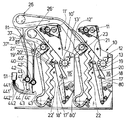
空気圧式たばこ装入スルースゲート11からたばこが予分配器10に供給される。この予分配器はレーキローラ12,13を備えている。予分配器10はたばこ溜め16に開口している。このたばこ溜めの出口側には急傾斜コンベヤ17が付設されている。この急傾斜コンベヤはたばこをすき取るパドルローラ18と、下方に案内された供給ダクト19内にたばこを叩いて取り出す個別化ローラ21と協働する。供給ダクト19は画成薄板20によって画成されている。供給ダクト19は垂直に配置されたジグザグふるい22の形をしたふるい手段の区間に側方から開口している。
Tobacco is supplied from the pneumatic cigarette charging
ジグザグふるい22はクロスフローブロワ23によって運転される空気循環システム24の一部である。空気循環システム24の流れ方向においてクロスフローブロワ23の下流に、空気循環曲管が設けられている。この空気循環曲管はその半径方向外側の範囲において空気循環システム24から分岐するバイパスに接続され、半径方向内側の範囲において余剰流れ通路に接続している。この余剰流れ通路には、搬送スクリューおよびロータリフィーダの形をしたたばこ余剰搬送手段が開口している。これらの詳細は図1に示されておらず、例えばドイツ連邦共和国特許出願第10154807.9号の図1または図4に示されている。これに関して、この特許出願の内容全体が参照される。
The
ふるい回路の空気循環システム24には更に、コアンダ分離器として形成されたたばこと空気の分離器26が統合されている。このたばこと空気の分離器は分離エッジ36の両側で、一方ではクロスフローブロワ23の吸込み側に接続され、他方では2個の堰止めダクト40,40′の上方に配置されたロータリフィーダ37に開口している。
Also integrated in the
ほぼ垂直に配置された堰止めダクト40,40′は下端のそのダクト出口がそれぞれ、打叩ローラ41,41′と協働する取り出しローラ42,42′を介して終わっている。このダクト出口は図3の実施の形態では、振動要素60,60′を備えた振動するダクト出口として形成されている。堰止めダクト40,40′とロータリフィーダ37との間にはたばこを分与するための回転翼弁38と、両堰止めダクト40,40′にたばこを分与して交互に充填する分配要素39が設けられている。
The
ロータリフィーダ37は空気循環システム24の残りの搬送空気をたばこから分離する働きをする。このたばこはロータリフィーダ37の上方のたばこ分離室81からロータリフィーダへ搬送される。図示していない他の実施の形態では、フィーダとして、ロータリフィーダ37と回転翼弁38の形をしたフィーダが2個設けられていないで、フィーダが1個だけ設けられている。図2の場合、回転翼弁37または37′の形をした1個のフィーダが設けられている。更に、個々のフィーダを設けることができる。このフィーダはロータリフィーダ37と回転翼弁38の機能を有する。すなわち、空気とたばこを分離し、たばこを分与する。
The
取り出しローラ42,42′の下方にはそれぞれ、案内通路が設けられている。この案内通路はそれぞれ流路の単一通路状の流動面44,44′に接続する案内面によって画成されている。案内通路は最初は上下に設けられている。吹き付け空気供給部43,43′によって、たばこを搬送するぴったり合った空気流が流動面44,44′に生じる。上方に案内される流動面44,44′は、二重連続体製造機械の連続体形成ユニットの下方に開口している。この場合、2個の連続体サクションコンベヤ50,50′が図1に概略的に示してあり、対応する数の連続体サクションコンベヤ50,50′を有する連続体形成ユニット51が図2に概略的に示してある。連続体サクションコンベヤはドイツ連邦共和国特許第3619579号に従って形成されている。上方に向かうたばこ充填流は図1に従って、平行に並べて配置された2つの連続体サクションコンベヤ50,50′に達する。連続体サクションコンベヤはそれぞれ、たばこ通路の底部内で多孔底に沿って移動する通気性のコンベヤベルトからなっている。このコンベヤベルトの背面は負圧室の吸引作用を受けている。余剰の搬送空気は空気吸い出し要素30,30′によって吸い出される。搬送空気自体は概略的に示した空気流43または43′によって流動面44,44′の方向に運ばれる。
Guide passages are provided below the take-out
たばこと空気の分離器26は管状体48周りに配置されている。
A tobacco and
ジグザグふるい22はたばこ葉肋のような分離除去されたふるい物質を搬出するスクリュー47を備えている。ドイツ連邦共和国特許出願第10154807.9号明細書に記載されている再ふるい器のような他の要素を設けることができる。
The
連続体形成軌道に沿って移送されるフリース状のたばこ流の形成の準備をしかつ紙巻きたばこ連続体製造機械の分配器に統合されたふるいシステムの作用は次の通りである。 The operation of the sieving system, which is prepared for the formation of a fleece-like cigarette stream transported along the continuum forming trajectory and integrated in the distributor of the cigarette continuum machine, is as follows.
たばこは装入スルースゲート11と予分配器10を経て、急傾斜コンベヤ17に至るたばこ溜め16内に達し、急傾斜搬送櫛状部を備えた急傾斜コンベヤ17がたばこ溜め16からたばこをすき取ることにより、連続的なたばこ流が急傾斜コンベヤ17によってふるいシステムに供給される。急傾斜コンベヤ17にたばこを均一に供給するために、余剰のたばこがパドルローラ18によって掻き取られる。例えば異物による損傷を回避するために、急傾斜コンベヤ17の回転数を監視することによって、低い定格回転数で機械を停止することができる。
The cigarette passes through the charging
急傾斜コンベヤ17上にあるたばこは個別化ローラ21の作用範囲に達する。この個別化装置は大まかな予備個別化によってたばこを加速してジグザグふるい22に移送する。個別化装置の回転数は、たばこ破壊と必要な個別化との妥協に関連して、好ましくは800〜900回転/分に調節される。
The cigarettes on the steeply
ジグザグふるい22の特徴的な形状のために、一方ではたばこ流の軽いたばこ繊維が上方に搬送され、他方ではたばこ流が主流に対して横方向に運動させられる。流れプロファイルが不均一であるので、高い空気速度の領域と低い空気速度の領域が生じる。この空気速度はたばこ繊維を旋回運動、いわゆる渦転動運動させる。これにより、たばこ流に含まれる葉肋が剥がれ、重力によって下方に移動する。軽いたばこ繊維はジグザグふるい22内で段毎に繰り返して上方に搬送される。この過程は突き出た先端部として形成されたすべてのふるい段で生じる。
Due to the characteristic shape of the
ジグザグふるい22から落下する葉肋物質には、再ふるいによって、空気循環システムから分岐するふるい空気が吹き付けられる。それによって、葉肋にまだ付着する軽いたばこ粒子が主空気流内に戻される。そして、たばこ葉肋はスルースゲートによって公知のごとく排出される。これに関して、特にドイツ連邦共和国特許出願第10154807.9号明細書が参照される。
The leaflet material falling from the
ふるいにかけられたたばこ流はたばこと空気の分離器26に達する。この分離器では、たばこと空気の分離が遠心力とコアンダ効果によって行われる。この場合、たばこ繊維は遠心力によって分離器26の曲がった外面の形をした外側形状部に沿って移動し、空気はコアンダ効果に基づいて管状体48の円筒面の形をした内側半径の形状部に接触する。分離エッジ36では、空気とたばこの最後の分離が行われる。この場合、たばこから分離された空気はクロスフローブロワ23に再び供給される。このクロスフローブロワは均一な流れプロファイルまたは分配器の幅にわたって(図面の平面に対して垂直に)均一な速度分布を有する。
The screened tobacco stream reaches the tobacco /
たばこと空気の分離器26で分離されたたばこはロータリフィーダ37によってふるいシステムから排出され、そしてたばこ量を分与するための回転翼弁38を経て2つの堰止めダクト40,40′に達する。この場合、図1に示した分配要素39の状態で、たばこは左側に示した堰止めダクト40に達する。堰止めダクト40,40′は装置内に並べて配置され、装置の全幅にわたって延びている。この幅は図面の平面に対して垂直である。
The tobacco separated by the tobacco and
堰止めダクト40,40′から、たばこが取り出しローラ42,42′と打叩ローラ41,41′によって細かくばらばらにされた形で案内面を経てノズル窪みとして形成された2つの流動面44,44′に移送される。吹き付け空気供給部は符号43,43′によって示してある。この場合、たばこ繊維をばらばらにするために、例えばドイツ連邦共和国特許出願第10154807.9号明細書またはヨーロッパ特許出願公開第1174046号公報に記載されているような付加的な吹き付け空気供給部をきわめて良好に使用することができる。
From the
0mb近くの小さな負圧の形態の理想圧力を維持しながら、公知のごとく、連続体形成ユニット51または図1に示すように連続体サクションコンベヤ50,50′へのぴったり合うたばこ流動床流れが生じる。この場合にも、装置の全幅にわたってたばこ流動床流れが達成される。好ましくは最適な流れ状態および圧力状態を調節および維持するために制御ユニットが設けられている。この場合特に図1において、余剰の空気を吸い出すことができるようにするために、空気吸い出し要素30,30′が連続体サクションコンベヤ50,50′の直前に配置されている。
While maintaining an ideal pressure in the form of a small negative pressure close to 0 mb, a well-known cigarette fluidized bed flow to the
連続体サクションコンベヤは図示していないたばこを方向91へ、すなわち図1,2,3の図面の平面内に搬送する。
The continuum suction conveyor transports cigarettes (not shown) in the
本発明による装置の全幅にわたってたばこ連続体を形成することにより、きわめて均質できわめて迅速なたばこ連続体形成が行われる。そのために好ましくは2つの堰止めダクトが使用される。この堰止めダクトは装置の全幅にわたって形成されているので、均一で迅速な連続体形成が可能である。 By forming a tobacco continuum over the entire width of the device according to the invention, a very homogeneous and very rapid tobacco continuum formation is achieved. For this purpose, preferably two weir ducts are used. Since the weir duct is formed over the entire width of the apparatus, uniform and quick continuum formation is possible.
図2はヨーロッパ特許出願第03006602.1号明細書記載のきわめて有利な装置を概略的に示している。例えば図1との違いは、たばこが2つの貯蔵個所80,80′から別々に堰止めダクト40,40′に供給可能であることにある。これによって、紙巻きたばこ連続体製造機械または本発明の種類の装置において、異なる銘柄の紙巻きたばこまたは異なるたばこからなる紙巻きたばこ連続体を製造することができる。図2の実施の形態では、これはそれぞれ異なる種類のたばこの2つの連続体である。たばこ装入スルースゲート11,11′および予分配器10または10′から堰止めダクト40,40′にたばこを供給するための装置の特徴は、図1の特徴に一致している。この場合、図2のたばこの搬送および予分配のための第2の装置に関して、それぞれの参照数字にダッシュが付けてある。図1の説明の内容全体が参照される。
FIG. 2 schematically shows a very advantageous device as described in European Patent Application No. 03006602.1. For example, the difference from FIG. 1 is that cigarettes can be supplied separately from the two
流動面441,441′,442,442′への流動面44,44′の分割はそれ自体公知である。4つのたばこ連続体を発生することができる。1つの流動面を2つの流動面に分割することは例えばドイツ連邦共和国特許第3619579号公報、ドイツ連邦共和国特許出願第10154807.9号明細書およびヨーロッパ特許出願公開第1174046号公報によって知られている。案内面44,44′のたばこ流を案内面441,442,441′,442′に分割することにより、4つのたばこ流が形成される。 The division of the flow surfaces 44, 44 'into the flow surfaces 441, 441', 442, 442 'is known per se. Four tobacco continuums can be generated. The division of one fluid surface into two fluid surfaces is known, for example, from German Patent 3619579, German Patent Application 101544807.9 and European Patent Application 1174046. . By dividing the tobacco flow on the guide surfaces 44 and 44 'into guide surfaces 441, 442, 441' and 442 ', four tobacco flows are formed.
流動面44,44′は好ましくは本実施の形態ではほぼ平行に配置されている。 The flow surfaces 44, 44 'are preferably arranged substantially parallel in the present embodiment.
図3は、たばこと搬送空気を分離するための本発明による装置26あるいは紙巻きたばこ連続体製造機械において少なくとも2つのたばこ連続体を形成するための本発明による装置の一部を示している。 FIG. 3 shows a part of the device according to the invention for separating tobacco and carrier air or a part of the device according to the invention for forming at least two tobacco continuums in a cigarette continuum making machine.
装置の構造はたばこ搬送方向上流側が例えば図1の構造と類似している。たばこはふるい22を通って、搬送空気流である空気流25によって搬送され、しかもたばこと空気の分離器26に搬送される。このたばこと空気の分離器はたばこと搬送空気を分離するための本発明による装置である。たばこと空気の分離器26はたばこと空気の分離器の外側の画成壁であるたばこ案内壁53を備えている。たばこと空気の分離器の出口側には、フラップ71が設けられている。このフラップは図3には2つの位置が図示してある。すなわち、参照数字71によって示した実線の位置と、参照数字71′によって示した一点鎖線の位置が図示してある。フラップ71,71′は回転軸73に枢着され、両位置71または71′に揺動可能である。フラップ71によって示した位置では、フラップ71がロータリフィーダ37に至る供給ホッパー32の案内壁33と一直線上に並んでいる。フラップ71のこの位置では、たばこは遠心力によってロータリフィーダ37に達する。ロータリフィーダ37の適当な充填が行われると、フラップ71は位置71′に揺動する。それによって、フラップ71′が供給ホッパー32′の案内壁33′と一直線上に並ぶので、たばこはロータリフィーダ37′に供給される。ロータリフィーダ37または37′はたばこから残りの搬送空気を分離する働きをし、更に堰止めダクト40または40′内にたばこを分与する働きをする。
The structure of the apparatus is similar to the structure of FIG. The cigarette passes through the
堰止めダクト40,40′は振動要素60,60′を備えている。堰止めダクト40,40′からたばこが取り出しローラ42,42′によって取り出される。他の方法過程または他の特徴は図1または図2の方法過程または特徴と一致している。
The
本発明による装置または本発明による構造体の利点は、図1と比較して構造高さが低いことにある。更に、フラップを1個だけしか必要としない。更に、図1または図2と比較して、すべてのたばこ落下区間が完全に垂直に配置されている。これは高い運転信頼性を生じる。 The advantage of the device according to the invention or the structure according to the invention is that the structure height is low compared to FIG. Furthermore, only one flap is required. Furthermore, all tobacco dropping sections are arranged completely vertically compared to FIG. 1 or FIG. This results in high operational reliability.
図2と比較しても構造高さが低い。というのは、たばこを2つの落下ダクトに供給するために、ふるいと空気循環システムを1つ使用するだけでよいからである。続いて、それぞれの落下ダクトからすき取られたたばこを各落下ダクト内で1つのたばこ連続体に変えることができるかあるいは図2に示すように各落下ダクト内で2つのたばこ連続体に変えることができる。たばこはフラップ71または71′によってロータリフィーダ37,37′に交互に供給される。ロータリフィーダ37,37′は共通の1個の駆動装置を備えていてもよい。
Compared with FIG. 2, the structural height is low. This is because it is only necessary to use one sieve and one air circulation system to supply cigarettes to the two drop ducts. Subsequently, cigarettes scraped from each drop duct can be changed to one cigarette continuum in each drop duct, or to two cigarette continuums in each drop duct as shown in FIG. Can do. Tobacco is alternately supplied to the
10,10′ 予分配器
11,11′ たばこ装入スルースゲート
12,12′ レーキローラ
13,13′ レーキローラ
16,16′ たばこ溜め
17,17′ 急傾斜コンベヤ
18,18′ パドルローラ
19,19′ 供給ダクト
20,20′ 画成薄板
21,21′ 個別化ローラ
22,22′ ジグザグふるい
23,23′ クロスフローブロワ
24 空気循環システム
25 空気流
26,26′ たばこ/空気分離器
30,30′ 空気吸い出し要素
32,32′ 供給ホッパー
33,33′ 案内壁
36 切断エッジ
37,37′ ロータリフィーダ
38 回転翼弁
39 分配要素
40,40′ 堰止めダクト
41,41′ 打叩ローラ
42,42′ 取り出しローラ
43,43′ 空気流
44,44′ 流動面
441,441′,442,442′ 流動面
47 スクリュー
48 管状体
50,50′ 連続体サクションコンベヤ
51 連続体形成ユニット
53 たばこ案内壁
60,60′ 振動要素
71,71′ フラップ
73 回転軸線
80,80′ 貯蔵たばこ
81,81′ たばこ分離室
91 搬送方向
10, 10 'Pre-distributor 11, 11' Tobacco charging
Claims (14)
Applications Claiming Priority (1)
| Application Number | Priority Date | Filing Date | Title |
|---|---|---|---|
| EP03024652 | 2003-10-27 |
Publications (1)
| Publication Number | Publication Date |
|---|---|
| JP2005124576A true JP2005124576A (en) | 2005-05-19 |
Family
ID=34486109
Family Applications (1)
| Application Number | Title | Priority Date | Filing Date |
|---|---|---|---|
| JP2004310737A Withdrawn JP2005124576A (en) | 2003-10-27 | 2004-10-26 | Device for separating tobacco and transport air and structure and method for forming at least two tobacco rods in endless rod maker |
Country Status (4)
| Country | Link |
|---|---|
| US (1) | US20050087199A1 (en) |
| EP (1) | EP1529449A1 (en) |
| JP (1) | JP2005124576A (en) |
| CN (1) | CN1611154A (en) |
Cited By (1)
| Publication number | Priority date | Publication date | Assignee | Title |
|---|---|---|---|---|
| WO2007094318A1 (en) * | 2006-02-14 | 2007-08-23 | Japan Tobacco Inc. | Cut tobacco raw material feeder for cigarette making machine |
Families Citing this family (4)
| Publication number | Priority date | Publication date | Assignee | Title |
|---|---|---|---|---|
| DE102009021811A1 (en) * | 2009-05-18 | 2010-11-25 | Hauni Maschinenbau Ag | Suction-belt conveyor and method for producing a strand of the tobacco-processing industry |
| DE102010054992A1 (en) * | 2010-12-17 | 2012-06-21 | Hauni Maschinenbau Ag | Apparatus and method for conveying strands of fibers of the tobacco processing industry |
| CN104310991B (en) * | 2014-09-30 | 2016-06-08 | 新昌县澄潭镇澄设机械厂 | A kind of rare earth doped nano-titanium-niobium coating and preparation method thereof |
| CH715607A1 (en) * | 2018-12-03 | 2020-06-15 | Koch Roger | Cigarette machine and process for making cigarettes. |
Family Cites Families (5)
| Publication number | Priority date | Publication date | Assignee | Title |
|---|---|---|---|---|
| US34040A (en) * | 1861-12-24 | Improved fuse-hood for shells | ||
| US217755A (en) * | 1879-07-22 | Improvement in portable railway-tracks | ||
| DE3619579C2 (en) * | 1986-06-11 | 1995-05-18 | Hauni Werke Koerber & Co Kg | Device for the simultaneous production of two continuous cigarette strands |
| DE10140309A1 (en) * | 2001-08-16 | 2003-02-27 | Hauni Maschinenbau Ag | Rod-like filler building apparatus, for cigarette making machine, includes sifter arranged to supply constituent such as shreds of tobacco leaf laminate, and air towards metering device |
| ATE332650T1 (en) * | 2002-05-21 | 2006-08-15 | Hauni Maschinenbau Ag | ARRANGEMENT AND METHOD FOR BUILDING AT LEAST TWO TOBACCO RODS IN A CIGARETTE ROD MACHINE |
-
2004
- 2004-09-25 EP EP04022900A patent/EP1529449A1/en not_active Withdrawn
- 2004-10-07 US US10/959,123 patent/US20050087199A1/en not_active Abandoned
- 2004-10-26 JP JP2004310737A patent/JP2005124576A/en not_active Withdrawn
- 2004-10-27 CN CNA2004100879532A patent/CN1611154A/en active Pending
Cited By (3)
| Publication number | Priority date | Publication date | Assignee | Title |
|---|---|---|---|---|
| WO2007094318A1 (en) * | 2006-02-14 | 2007-08-23 | Japan Tobacco Inc. | Cut tobacco raw material feeder for cigarette making machine |
| US7874295B2 (en) | 2006-02-14 | 2011-01-25 | Japan Tobacco Inc. | Shredded tobacco material feeder of a cigarette manufacturing apparatus |
| JP4822462B2 (en) * | 2006-02-14 | 2011-11-24 | 日本たばこ産業株式会社 | Cigarette production machine |
Also Published As
| Publication number | Publication date |
|---|---|
| US20050087199A1 (en) | 2005-04-28 |
| CN1611154A (en) | 2005-05-04 |
| EP1529449A1 (en) | 2005-05-11 |
Similar Documents
| Publication | Publication Date | Title |
|---|---|---|
| JP4338370B2 (en) | Apparatus for forming at least one cigarette continuum in a cigarette continuum forming machine | |
| JP5512540B2 (en) | Various embodiments for an apparatus, system, and method for producing a coaxial core tobacco rod making machine having an air carrier | |
| JP2004000224A (en) | Arrangement device and method for constituting at least two tobacco continuous bodies in cigarette continuous body manufacturing machine | |
| JP2004337160A (en) | Method for producing fleece used for producing filter in tobacco processing industry and device for adjusting fiber terminal in apparatus for producing filter continuous material | |
| JPH05236928A (en) | Method and device for producing continuos body from tobacco fiber | |
| RU2230472C2 (en) | Method and apparatus for manufacture of filtering cable treated with additive | |
| JP3138266B2 (en) | Loading equipment for dual continuum manufacturing machines in the tobacco processing industry. | |
| KR20050090127A (en) | Process and apparatus for high-speed filling of composite cigarette filters | |
| NL8802510A (en) | METHOD FOR MANUFACTURING A TOBACCO STRING. | |
| JPH02186968A (en) | Rotary seal for using in device for continuously feeding tobacco to cigarette making machine | |
| JP2001522596A (en) | Method for transporting tobacco stream, supply device, and tobacco maker provided with such supply device | |
| JPH04320674A (en) | Method and apparatus for making tobacco continuous-rod | |
| JP2005124576A (en) | Device for separating tobacco and transport air and structure and method for forming at least two tobacco rods in endless rod maker | |
| JP2009136287A (en) | Device for forming continuous body in machine for tobacco processing industry | |
| CN100364465C (en) | Cigarette manufacturing method and machine | |
| US6814080B2 (en) | Apparatus for making a tobacco rod | |
| JPH03168077A (en) | Method and apparatus for manufacturing tobacco succession | |
| JP3190325B2 (en) | Method and apparatus for producing two endless tobacco continuum | |
| EP0730832A1 (en) | Device for the removal of the excess of air in a distributor of the tobacco industry | |
| US3779253A (en) | Cigarettes | |
| JP2007222165A (en) | Circulating body in cigarette strand-producing machine | |
| JPS63188376A (en) | Method and apparatus for feeding tobacco to tobacco manufacturing machine | |
| JPH05506567A (en) | Tobacco feeding system for cigarette making machines | |
| JPH04244277A (en) | Device to strain tabacco particle | |
| WO2005011412A1 (en) | Cut tobacco feeding device for cigarette manufacturing machine |
Legal Events
| Date | Code | Title | Description |
|---|---|---|---|
| A300 | Application deemed to be withdrawn because no request for examination was validly filed |
Free format text: JAPANESE INTERMEDIATE CODE: A300 Effective date: 20080108 |