JP2005123761A - Superconductivity plane circuit filter and radio receiver using the same - Google Patents
Superconductivity plane circuit filter and radio receiver using the same Download PDFInfo
- Publication number
- JP2005123761A JP2005123761A JP2003354565A JP2003354565A JP2005123761A JP 2005123761 A JP2005123761 A JP 2005123761A JP 2003354565 A JP2003354565 A JP 2003354565A JP 2003354565 A JP2003354565 A JP 2003354565A JP 2005123761 A JP2005123761 A JP 2005123761A
- Authority
- JP
- Japan
- Prior art keywords
- filter
- pattern
- resonators
- resonator
- dielectric substrate
- Prior art date
- Legal status (The legal status is an assumption and is not a legal conclusion. Google has not performed a legal analysis and makes no representation as to the accuracy of the status listed.)
- Withdrawn
Links
Images
Landscapes
- Control Of Motors That Do Not Use Commutators (AREA)
- Structure Of Receivers (AREA)
Abstract
Description
本発明は、超電導平面回路フィルタに関し、特に、高温超電導体パターンを用いて誘電体基板の表面に複数の共振器が形成されたフィルタ回路基板を用いる超電導平面回路フィルタおよびそれを用いた無線受信機に関する。 The present invention relates to a superconducting planar circuit filter, and more particularly to a superconducting planar circuit filter using a filter circuit board in which a plurality of resonators are formed on the surface of a dielectric substrate using a high-temperature superconductor pattern and a radio receiver using the same. About.
携帯電話サービスなどの移動無線通信の飛躍的な普及により、準マイクロ波、マイクロ波、ミリ波などの高周波帯域を利用する無線通信機器において希望周波数信号のみを通過させるために、急峻な濾波特性をもったフィルタが必要とされている。このような急峻な濾波特性をもったフィルタを実現するために、誘電体基板の上に、高温超電導体で構成した複数の共振器を多段に配置することが提案されている。このような例のものを、従来の常導電体で作ったものと比較すると、Q値を2桁以上改良できることが分かった。 With the rapid spread of mobile radio communications such as mobile phone services, sharp filtering characteristics have been adopted to allow only desired frequency signals to pass through in radio communication equipment that uses high-frequency bands such as quasi-microwaves, microwaves, and millimeter waves. A filter with a need is needed. In order to realize a filter having such steep filtering characteristics, it has been proposed to arrange a plurality of resonators composed of high-temperature superconductors in multiple stages on a dielectric substrate. It was found that the Q value can be improved by two orders of magnitude or more when such an example is compared with a conventional ordinary conductor.
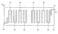
図5(A)は、上述の提案の超電導平面回路フィルタに用いられるフィルタ回路基板の従来例を示す平面図、図5(B)は、図5(A)のラインP1−P1から見たフィルタ回路基板の断面図である。図5のフィルタ回路基板の誘電体基板101の表面には、1/2波長U字形状(ヘアピン形状)の複数の共振器102がラインP1−P1に沿って順次に上下の向きを変えながら配置され、全体として帯域通過フィルタを形成している。また、誘電体基板101の裏面にはグランドパターン106が形成されている。この共振器102、電極用パターン103,104およびグランドパターン106は、高温超電導体材料から形成されている。入力信号は、電極用パターン103に入力され、濾波されて電極用パターン104から出力される。この場合、共振器102と共振器102との間の間隔108a,108bが共振器102と共振器102との間の電磁結合量(共振器結合量)を決定している。
FIG. 5A is a plan view showing a conventional example of a filter circuit board used in the proposed superconducting planar circuit filter, and FIG. 5B is a filter viewed from line P1-P1 in FIG. 5A. It is sectional drawing of a circuit board. On the surface of the
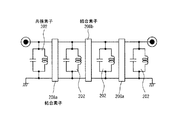
上述の電磁結合をも含めて図5で示されるものを等価回路で示すと図6のようになる。すなわち、等価回路は、図5の共振器102に基づき並列共振の中心周波数が同じである4つの共振素子202と、相互間が図5(B)の間隔108a,108bに対応して決まる結合量に基づく結合素子208a,208bとで示されている。また、電極用パターン103,104は、誘電体基板101の両端近くに配置された共振器102に対して間隔107をもって電磁結合をするように配置されている。このような構造の場合、図5で示される回路の通過帯域幅を変更しようとすると、共振器間の間隔108a,108bを変更しなければならない。これらの間隔108a,108bを変更すると、それに伴って誘電体基板101の大きさ、例えば、長さLも変わってくる。
FIG. 6 shows the equivalent circuit shown in FIG. 5 including the above-described electromagnetic coupling. That is, the equivalent circuit is based on the
図7(A)は、図5および図6で示された誘電体基板101を超電導平面回路フィルタとして組み立てたところを示している平面図、図7(B)は、図7(A)のラインP3−P3から見た断面図である。RF入力コネクタ303と、RF出力コネクタ304とが組み付けられたキャビティ306の底面に誘電体基板101の裏面のグランドパターン106が接触するように配置し、誘電体基板101の外縁の数個所を固定用板ばね309によってキャビティ306の底面に固定する。その後に、RF入出力コネクタ303,304と、電極用パターン103,104とを接続部305のようにボンディング接続する。
7A is a plan view showing a state where the
このように組み立てられる超電導平面回路フィルタにおいて、上述したように誘電体基板101の長さLが変わってくると、誘電体基板101を収納するためのキャビティ306の大きさも変更しなければならなくなる場合がある。また、急峻なスカート特性をもつフィルタを作成しようとするときには、共振器を図8のようにさらに多段に配置しなければならなくなる。しかし、このように常電導体パターンの共振器を多段に配置すると挿入損失が著しく増加してしまうという問題がある。そこで、フィルタの形成に超電導材料を利用することが提案されている。(例えば、特許文献1参照)。
上述した多段構成のフィルタも超電導体パターンの共振器を用いれば、挿入損失が著しく増加すること無く作成することが比較的に容易である。しかし、共振器を多段に配置し、所望の特性を得るためには、共振器の間隔と結合量とに関する詳細なデータが必要であり、フィルタを実際に設計あるいは試作するには多大な時間が必要となる。また、これらの間隔の決定にはキャビティの大きさも関係し、それによっては誘電体基板の大きさも再設定する必要が生じてくる。すなわち、共振器と共振器との間の結合量が所望の値となるように、共振器と共振器の間隔だけで制御しようとすると、フィルタに与えようとする帯域幅などの特性が変わる毎にフィルタの誘電基板やキャビティの大きさを変えなければならず、開発、設計、試作に多大な時間や費用を必要とし、コスト高の主要な原因となっている。 The above-described multi-stage filter is relatively easy to produce without significantly increasing insertion loss if a superconductor-patterned resonator is used. However, in order to obtain the desired characteristics by arranging the resonators in multiple stages, detailed data on the distance between the resonators and the amount of coupling is necessary, and it takes a lot of time to actually design or prototype the filter. Necessary. In addition, the determination of these intervals also involves the size of the cavity, which may require resetting the size of the dielectric substrate. That is, if control is performed only by the distance between the resonators so that the coupling amount between the resonators becomes a desired value, the characteristics such as the bandwidth to be applied to the filter change. In addition, the size of the dielectric substrate and cavity of the filter must be changed, requiring a lot of time and money for development, design and prototyping, which is a major cause of high cost.
本発明は上述した問題点を解決するためになされたものであり、誘電体基板やキャビティの寸法を変えないでも、共振器の間の電磁結合量を調節できるようにし、所望のフィルタ特性の獲得を可能にさせることにより、類似しているフィルタに関しては、特性が異なっていたとしても、同じ寸法の誘電体基板やキャビティを使用することができるファミリ化構造とし、フィルタの開発、設計、試作に要する時間およびコストを大幅に低減できる超電導平面回路フィルタおよびそれを用いた無線受信機を提供することを目的とする。 The present invention has been made to solve the above-described problems, and allows the amount of electromagnetic coupling between the resonators to be adjusted without changing the dimensions of the dielectric substrate and the cavity, thereby obtaining desired filter characteristics. For similar filters, even if the characteristics are different, a family-structured structure that can use dielectric substrates and cavities of the same dimensions can be used for filter development, design, and prototyping. It is an object of the present invention to provide a superconducting planar circuit filter and a radio receiver using the same, which can significantly reduce the time and cost required.
上述した課題を解決するために本発明に係る超電導平面回路フィルタは、高温超電導体パターンを用いて誘電体基板の表面に複数の共振器が形成されたフィルタ回路基板を用いる超電導平面回路フィルタにおいて、前記共振器と共振器との間の誘電体基板の表面に、前記共振器間の電磁結合量をパターン形状変更により調節できる結合制御用パターンを有する。 In order to solve the above-described problem, a superconducting planar circuit filter according to the present invention is a superconducting planar circuit filter using a filter circuit substrate in which a plurality of resonators are formed on the surface of a dielectric substrate using a high-temperature superconductor pattern. A coupling control pattern capable of adjusting the amount of electromagnetic coupling between the resonators by changing a pattern shape is provided on the surface of the dielectric substrate between the resonators.
このような構成によれば、フィルタを形成する各部のパターンは高温超電導体パターンで形成されているので、挿入損失は小さくすることができる。また、帯域幅などを決定する共振器間の電磁結合量は、結合制御用パターンのパターン幅などのパターン形状を変更することにより、誘電体基板の大きさを変えること無く容易に調整でき、所望のフィルタ特性を実現することができる。さらに、誘電体基板の大きさを変える必要がないことから、フィルタ特性が異なってもフィルタ回路基板を収納して超電導平面回路フィルタを完成するためのキャビティの寸法も変える必要が無く、ファミリ化が容易になる。 According to such a configuration, since the pattern of each part forming the filter is formed of a high-temperature superconductor pattern, insertion loss can be reduced. In addition, the amount of electromagnetic coupling between resonators that determines the bandwidth and the like can be easily adjusted without changing the size of the dielectric substrate by changing the pattern shape such as the pattern width of the coupling control pattern. The filter characteristics can be realized. In addition, since there is no need to change the size of the dielectric substrate, it is not necessary to change the dimensions of the cavity for housing the filter circuit board and completing the superconducting planar circuit filter even if the filter characteristics are different, making the family It becomes easy.
また、本発明に係る無線受信機は、請求項1記載の超電導平面回路フィルタと、増幅器と、前記超伝導平面回路フィルタ及び前記増幅器を収容する断熱容器と、前記断熱容器を冷却する冷却手段とを用いている。したがって、その無線受信機に必要なフィルタの帯域幅などを容易に設定することができる。 A radio receiver according to the present invention includes a superconducting planar circuit filter according to claim 1, an amplifier, a heat insulating container that houses the superconducting flat circuit filter and the amplifier, and a cooling unit that cools the heat insulating container. Is used. Therefore, it is possible to easily set the filter bandwidth necessary for the wireless receiver.
以上に詳述したように本発明の超電導平面回路フィルタによれば、フィルタを形成する各部のパターンは高温超電導体パターンで形成されているので、挿入損失は小さくすることができる。また、帯域幅などを決定する共振器間の電磁結合量は、結合制御用パターンのパターン幅などのパターン形状を変更することにより、誘電体基板の大きさを変えること無く容易に調整でき、容易に所望のフィルタ特性を実現することができる。さらに、誘電体基板の大きさを変える必要がないことから、フィルタ特性が異なってもフィルタ回路基板を収納して超電導平面回路フィルタを完成するためのキャビティの寸法も変える必要が無く、設計、試作、ファミリ化などが容易になる。 As described in detail above, according to the superconducting planar circuit filter of the present invention, the pattern of each part forming the filter is formed of a high-temperature superconductor pattern, so that the insertion loss can be reduced. In addition, the amount of electromagnetic coupling between resonators that determines the bandwidth can be easily adjusted without changing the size of the dielectric substrate by changing the pattern shape such as the pattern width of the coupling control pattern. In addition, desired filter characteristics can be realized. Furthermore, since there is no need to change the size of the dielectric substrate, there is no need to change the dimensions of the cavity for housing the filter circuit board and completing the superconducting planar circuit filter even if the filter characteristics are different. , Making it easier to make a family.
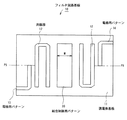
以下、本発明の実施の形態について図面を参照しつつ説明する。図1は本発明の超電導平面回路フィルタに用いられるフィルタ回路基板の第1の実施の形態を示す平面図、図2は、図1のフィルタ回路基板を用いて超電導平面回路フィルタを構成した場合の結合制御用パターンのパターン幅と、共振器結合量との関係を特性曲線で示すグラフ、図3(A)は、本発明の超電導平面回路フィルタに用いられるフィルタ回路基板の第2の実施の形態を示す平面図、図3(B)は、図3(A)のラインP7−P7から見たフィルタ回路基板の断面図、図4(A)は、超電導平面回路フィルタに用いられるフィルタ回路基板の第3の実施の形態を示す平面図、図4(B)は、図4(A)のラインP8−P8から見たフィルタ回路基板の断面図である。 Embodiments of the present invention will be described below with reference to the drawings. FIG. 1 is a plan view showing a first embodiment of a filter circuit board used in the superconducting planar circuit filter of the present invention, and FIG. 2 is a case where a superconducting planar circuit filter is constructed using the filter circuit board of FIG. FIG. 3A is a graph showing the relationship between the pattern width of the coupling control pattern and the resonator coupling amount as a characteristic curve. FIG. 3A is a second embodiment of the filter circuit board used in the superconducting planar circuit filter of the present invention. FIG. 3B is a cross-sectional view of the filter circuit board viewed from line P7-P7 in FIG. 3A, and FIG. 4A is a filter circuit board used for a superconducting planar circuit filter. FIG. 4B is a plan view showing the third embodiment, and FIG. 4B is a cross-sectional view of the filter circuit board as seen from line P8-P8 in FIG. 4A.
図1に示されたフィルタ回路基板10に用いられる誘電体基板11の上には、電極用パターン13と、電極用パターン13から間隔をあけて配置された下向きのU字形状(ヘアピン形状)の共振器12と、下向きのU字形状の共振器12から所定の間隔をあけて配置されたパターン幅Mの結合制御用パターン30と、結合制御用パターン30から間隔をあけて配置された上向きのU字形状の共振器12と、上向きのU字形状の共振器12から間隔をあけて配置された電極用パターン14とが形成されている。また、誘電体基板11の裏面にはグランドパターン(不図示)が形成されている。この例における共振器12、結合制御用パターン30、電極用パターン13,14およびグランドパターンは、高温超電導体材料から形成されている。入力信号は、電極用パターン13に入力され、濾波されて電極用パターン14から出力される。
On the
上述のフィルタ回路基板10を用いて超電導平面回路フィルタを図7に示されると同様な構成で作成すると、結合制御用パターン30のパターン幅Mと、共振器間の電磁結合を示す共振器結合量との関係は、図2のように表される。したがって、図1に示されるようなフィルタ回路基板10を設計する場合には、共振器12を図1のように配置するとともに、所望のフィルタ特性を得るための共振器間の共振器結合量を設定するために、結合制御用パターン30の図1のような形状およびパターン幅Mを図2の特性曲線に従って決定する。図2の特性曲線によれば、結合制御用パターン30を配置しないフィルタ回路基板10を用いた場合には、共振器結合量が“0.003”であり、2.3mmのパターン幅Wの結合制御用パターン30を配置するとその共振器結合量が“0.025”に増加することが分かる。
When a superconducting planar circuit filter is formed using the filter circuit board 10 with the same configuration as shown in FIG. 7, the pattern width M of the
図2の特性曲線から明らかなように、超電導平面回路フィルタの所望のフィルタ特性を実現するように、結合制御用パターン30のパターン幅Mを“0.0mm”から“2.3mm”の間の適宜な値に設定することにより、結共振器間の共振器結合量を“0.003”から“0.025”までの値に設定することができる。このようにすれば、作成する超電導平面回路フィルタの特性が異なっていても、特性が類似している限り、結合制御用パターン30のパターン幅Mを変更するだけで所望の特性の超電導平面回路フィルタを実現でき、その場合、誘電体基板およびキャビティの寸法を同じ寸法にすることができる。この例においては、結合制御用パターン30は、形状が矩形で、パターン幅Mのみを変更することとしたが、矩形を他の形状に変えてもよいし、共振器との相互位置関係を適宜に変更してもよいことはいうまでもない。
As is apparent from the characteristic curve of FIG. 2, the pattern width M of the
上述の例において、誘電体基板11の材料としては、酸化チタン、ランタンアルミネート、酸化セリウムコートサファイア、酸化マグネシューム、チタン酸ストロンチウム、チタン酸マグネシウムが好ましい。また、この例における共振器12、結合制御用パターン30、電極用パターン13,14およびグランドパターンを形成するための高温超電導体材料からなる高温超電導体パターンは、YB2Cu3O7_δを用いて、例えば、厚さ0.4μm〜1.0μmの膜に形成するのが好ましい。なお、共振器12は、高温超電導体材料から形成するが、その他のパターンは、高温超電導体材料以外の材料から構成してもよい。例えば、結合制御用パターン30を誘電体材料のパターンあるいは誘電体材料のプレートに置き換えてもよい。
In the above example, the material of the
次に、この発明の超電導平面回路フィルタの第2の実施の形態について説明する。図3(A)は、本発明の超電導平面回路フィルタに用いられるフィルタ回路基板の第2の実施の形態を示す平面図、図3(B)は、図3(A)のラインP7−P7から見たフィルタ回路基板の断面図である。図3のフィルタ回路基板10aにおいて、誘電体基板11の表面には、1/2波長U字形状(ヘアピン形状)の複数の共振器12がラインP7−P7に沿って順次に上下の向きを変えながら配置され、共振器間には、幅wa,wbの結合制御用パターン38a,38bが配置され、両端縁は電極用パターン13,14が配置され、全体として帯域通過フィルタを形成している。また、誘電体基板11の裏面にはグランドパターン16が形成されている。
Next, a second embodiment of the superconducting planar circuit filter of the present invention will be described. FIG. 3A is a plan view showing a second embodiment of a filter circuit board used in the superconducting planar circuit filter of the present invention, and FIG. 3B is a view from lines P7 to P7 in FIG. It is sectional drawing of the seen filter circuit board. In the
図3のフィルタ回路基板10aにおいて、これらの共振器12、結合制御用パターン38a,38b、電極用パターン13,14およびグランドパターン16は、高温超電導体材料から形成されている。入力信号は、電極用パターン13に入力され、濾波されて電極用パターン14から出力される。この場合、共振器間の結合制御用パターン38a,38bが共振器間の共振器結合量を決定している。その他、誘電基板11の材料、共振器12、結合制御用パターン38a,38b、電極用パターン13,14およびグランドパターンを形成するための高温超電導体材料などについては図1で示されたものと同様なことが言える。特に、例えば、結合制御用パターン38a,38bを誘電体材料のパターンあるいは誘電体材料のプレートに置き換えることも可能である。
In the
次に、この発明の超電導平面回路フィルタの第3の実施の形態について図4(A)および図4(B)を参照して説明する。図4(A)は、超電導平面回路フィルタに用いられるフィルタ回路基板の第3の実施の形態を示す平面図、図4(B)は、図4(A)のラインP8−P8から見たフィルタ回路基板の断面図である。図4のフィルタ回路基板10bにおいては、2枚の誘電体基板11の間で図3と同様に、高温超電導材料からなる共振器12、結合制御用パターン38a,38b、電極用パターン13,14が形成されているとともに、フィルタ回路基板10bの上下の外面には高温超電導材料からなるグランドパターン16が形成され、いわゆるトリプレートストリップライン構造の4段帯域通過フィルタとして形成されている。
Next, a third embodiment of the superconducting planar circuit filter of the present invention will be described with reference to FIGS. 4 (A) and 4 (B). FIG. 4A is a plan view showing a third embodiment of a filter circuit board used in a superconducting planar circuit filter, and FIG. 4B is a filter viewed from lines P8-P8 in FIG. 4A. It is sectional drawing of a circuit board. In the
図4の場合においても、通過帯域幅に主に関係する共振器間の結合量を共振器間の間隔の調整に依存せずに、結合制御用パターン38a,38bのパターン幅wa,wbの調節で実現できるので、異なる通過帯域幅のフィルタを開発・設計・試作する際に同じ大きさのフィルタ回路基板に形成することができる。したがって、誘電体基板やキャビティをファミリ化することができ、設計時間の短縮、部品の共通化、コストの低減が可能となる点は、図1および図3の場合と同じである。同様に、結合制御用パターン38a,38bを誘電体材料のパターンあるいは誘電体材料のプレートに置き換えることも可能である。
In the case of FIG. 4 as well, adjustment of the pattern widths wa and wb of the
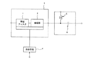
携帯電話サービスなどの移動無線通信の飛躍的な普及により、準マイクロ波、マイクロ波、ミリ波などの高周波帯域を利用する無線通信機器において希望周波数信号のみを通過させるために、急峻な濾波特性をもったフィルタが必要とされているが、このような急峻な濾波特性をもったフィルタを実現するために、上述の超電導平面回路フィルタを用いれば、Q値が非常に高く保つことができ、フィルタ特性も容易に調節できる。したがって、例えば、新規な無線受信機などを短時間で設計・試作を行うことができ、ひいては、コストを大幅に低減することができる。例えば、図9は本発明の無線受信機の一例を示すブロック図であり、本発明の超伝導平面回路フィルタによる帯域フィルタ1と、増幅器(例えば低雑音増幅器)2と、これら帯域フィルタ1と増幅器2を断熱して収容する断熱容器3と、断熱容器3を冷却する冷却手段4と、増幅器2の出力端に設けられるチョークコイル5及びコンデンサ6とを備えている。
With the rapid spread of mobile radio communications such as mobile phone services, sharp filtering characteristics have been adopted to allow only desired frequency signals to pass through in radio communication equipment that uses high-frequency bands such as quasi-microwaves, microwaves, and millimeter waves. In order to realize a filter having such a steep filtering characteristic, the Q value can be kept very high by using the above-described superconducting planar circuit filter. The characteristics can be easily adjusted. Therefore, for example, a new wireless receiver or the like can be designed and prototyped in a short time, and the cost can be greatly reduced. For example, FIG. 9 is a block diagram showing an example of a radio receiver according to the present invention. The bandpass filter 1 is composed of a superconducting planar circuit filter according to the present invention; 2 is provided with a heat insulating container 3 that insulates and accommodates 2, a cooling means 4 that cools the heat insulating container 3, and a choke coil 5 and a
なお、増幅器2を動作させる直流電源は外部より供給される。そして、上記直流電源はチョークコイル5を通過して増幅器2に供給される。チョークコイル5では、直流は通過させるが、高周波は通過させない。よって、図9の回路では増幅器2によって増幅された信号がチョーク回路5を通過することはない。同様に、コンデンサ6はバイパスコンデンサであり、チョークコイル5から増幅器2に供給される直流電力をコンデンサ6で遮断して、直流はすべて増幅器2に供給されるようにしている。増幅器2で増幅された高周波信号はコンデンサ6を通過することができる。
Note that a DC power source for operating the
1 帯域フィルタ、2 増幅器、3 断熱容器、4 冷却手段、5 チョークコイル、6 コンデンサ、10,10a,10b フィルタ回路基板、11 誘電体基板、12 共振器、13,14 電極用パターン、16 グランドパターン 1 band filter, 2 amplifier, 3 heat insulation container, 4 cooling means, 5 choke coil, 6 capacitor, 10, 10a, 10b filter circuit board, 11 dielectric substrate, 12 resonator, 13, 14 electrode pattern, 16 ground pattern
Claims (2)
前記共振器と共振器との間の誘電体基板の表面に、前記共振器間の電磁結合量をパターン形状変更により調節できる結合制御用パターンを有することを特徴とする超電導平面回路フィルタ。 In a superconducting planar circuit filter using a filter circuit board in which a plurality of resonators are formed on the surface of a dielectric substrate using a high-temperature superconductor pattern,
A superconducting planar circuit filter comprising a coupling control pattern capable of adjusting an electromagnetic coupling amount between the resonators by changing a pattern shape on a surface of a dielectric substrate between the resonators.
Priority Applications (1)
| Application Number | Priority Date | Filing Date | Title |
|---|---|---|---|
| JP2003354565A JP2005123761A (en) | 2003-10-15 | 2003-10-15 | Superconductivity plane circuit filter and radio receiver using the same |
Applications Claiming Priority (1)
| Application Number | Priority Date | Filing Date | Title |
|---|---|---|---|
| JP2003354565A JP2005123761A (en) | 2003-10-15 | 2003-10-15 | Superconductivity plane circuit filter and radio receiver using the same |
Publications (1)
| Publication Number | Publication Date |
|---|---|
| JP2005123761A true JP2005123761A (en) | 2005-05-12 |
Family
ID=34612438
Family Applications (1)
| Application Number | Title | Priority Date | Filing Date |
|---|---|---|---|
| JP2003354565A Withdrawn JP2005123761A (en) | 2003-10-15 | 2003-10-15 | Superconductivity plane circuit filter and radio receiver using the same |
Country Status (1)
| Country | Link |
|---|---|
| JP (1) | JP2005123761A (en) |
Cited By (6)
| Publication number | Priority date | Publication date | Assignee | Title |
|---|---|---|---|---|
| CN1925212B (en) * | 2005-08-31 | 2010-05-12 | 中国科学院物理研究所 | A Planar Superconducting Microstrip Resonator |
| JP2012222725A (en) * | 2011-04-13 | 2012-11-12 | Toshiba Corp | Active array antenna device |
| JP2014082794A (en) * | 2014-01-31 | 2014-05-08 | Toshiba Corp | Active array antenna device |
| CN104871363A (en) * | 2012-12-24 | 2015-08-26 | 上海贝尔股份有限公司 | An adjustable coupling for use with an input resonator and/or an output resonator of a bandpass filter |
| RU2763482C1 (en) * | 2020-12-16 | 2021-12-29 | Федеральное государственное бюджетное образовательное учреждение высшего образования "Сибирский государственный университет науки и технологий имени академика М.Ф. Решетнева" (СибГУ им. М.Ф. Решетнева) | Strip band-pass filter |
| JP7498189B2 (en) | 2019-02-28 | 2024-06-11 | キョーセラ・エイブイエックス・コンポーネンツ・コーポレーション | Surface-mountable high-frequency microstrip bandpass filters |
-
2003
- 2003-10-15 JP JP2003354565A patent/JP2005123761A/en not_active Withdrawn
Cited By (8)
| Publication number | Priority date | Publication date | Assignee | Title |
|---|---|---|---|---|
| CN1925212B (en) * | 2005-08-31 | 2010-05-12 | 中国科学院物理研究所 | A Planar Superconducting Microstrip Resonator |
| JP2012222725A (en) * | 2011-04-13 | 2012-11-12 | Toshiba Corp | Active array antenna device |
| US8749430B2 (en) | 2011-04-13 | 2014-06-10 | Kabushiki Kaisha Toshiba | Active array antenna device |
| CN104871363A (en) * | 2012-12-24 | 2015-08-26 | 上海贝尔股份有限公司 | An adjustable coupling for use with an input resonator and/or an output resonator of a bandpass filter |
| CN104871363B (en) * | 2012-12-24 | 2017-03-15 | 上海贝尔股份有限公司 | For the scalable coupling device that the input resonator and/or output resonator with band filter is used together |
| JP2014082794A (en) * | 2014-01-31 | 2014-05-08 | Toshiba Corp | Active array antenna device |
| JP7498189B2 (en) | 2019-02-28 | 2024-06-11 | キョーセラ・エイブイエックス・コンポーネンツ・コーポレーション | Surface-mountable high-frequency microstrip bandpass filters |
| RU2763482C1 (en) * | 2020-12-16 | 2021-12-29 | Федеральное государственное бюджетное образовательное учреждение высшего образования "Сибирский государственный университет науки и технологий имени академика М.Ф. Решетнева" (СибГУ им. М.Ф. Решетнева) | Strip band-pass filter |
Similar Documents
| Publication | Publication Date | Title |
|---|---|---|
| Kuo et al. | Microstrip stepped impedance resonator bandpass filter with an extended optimal rejection bandwidth | |
| Chen et al. | Design of microstrip bandpass filters with multiorder spurious-mode suppression | |
| US7567153B2 (en) | Compact bandpass filter for double conversion tuner | |
| Velazquez-Ahumada et al. | Application of stub loaded folded stepped impedance resonators to dual band filters | |
| US9780427B2 (en) | Bandpass filter and method of fabricating the same | |
| CN107579317B (en) | Balun bandpass filter based on the line of rabbet joint and micro-strip multimode resonator | |
| KR101451705B1 (en) | Multiple Split Ring Resonator Using Metamaterial having Negative Permeability | |
| Chen et al. | A miniaturized multilayer quasi-elliptic bandpass filter with aperture-coupled microstrip resonators | |
| US7495531B2 (en) | Filter and radio communication apparatus using the same | |
| JP2007281601A (en) | Filter circuit and method for adjusting characteristics thereof | |
| JP2009055576A (en) | Filter circuit having plurality sets of attenuating poles | |
| JP2005123761A (en) | Superconductivity plane circuit filter and radio receiver using the same | |
| JP2004112668A (en) | Resonator and filter | |
| US6184760B1 (en) | Half-wavelength resonator type high frequency filter | |
| JP6265460B2 (en) | Dual band resonator and dual band bandpass filter using the same | |
| JP4731515B2 (en) | Tunable filter and manufacturing method thereof | |
| JPH10190308A (en) | Lamination type filter | |
| JPH11312903A (en) | Dielectric filter, dielectric duplexer and communication equipment | |
| JPH10322155A (en) | Band-stop filter | |
| Sanchez-Soriano et al. | Dual band bandpass filters based on strong coupling directional couplers | |
| KR100313893B1 (en) | narrow band superconducting band pass filter | |
| Yang et al. | 60 GHz compact integrated cross-coupled SIR-MH bandpass filter on bulk CMOS | |
| JP2004289755A (en) | High frequency filter control method, high frequency filter manufacturing method, and high frequency filter | |
| Djaiz et al. | A design and fabrication of a new stacked bandpass filter using multilayer microstrip structure for wireless applications | |
| Lei et al. | Miniature dual-band bandpass filter based on E-shape dual-mode resonator |
Legal Events
| Date | Code | Title | Description |
|---|---|---|---|
| A300 | Withdrawal of application because of no request for examination |
Free format text: JAPANESE INTERMEDIATE CODE: A300 Effective date: 20070109 |


