JP2005123711A - Portable electronic apparatus - Google Patents
Portable electronic apparatus Download PDFInfo
- Publication number
- JP2005123711A JP2005123711A JP2003353655A JP2003353655A JP2005123711A JP 2005123711 A JP2005123711 A JP 2005123711A JP 2003353655 A JP2003353655 A JP 2003353655A JP 2003353655 A JP2003353655 A JP 2003353655A JP 2005123711 A JP2005123711 A JP 2005123711A
- Authority
- JP
- Japan
- Prior art keywords
- imaging
- front member
- main body
- portable electronic
- electronic device
- Prior art date
- Legal status (The legal status is an assumption and is not a legal conclusion. Google has not performed a legal analysis and makes no representation as to the accuracy of the status listed.)
- Withdrawn
Links
Images

Abstract
Description
本発明は携帯型電子機器に係り、特に、CCDカメラなどの撮像手段を備えた電子機器の構造に関する。 The present invention relates to a portable electronic device, and more particularly to the structure of an electronic device provided with an imaging means such as a CCD camera.
一般に、CCDカメラなどの撮像手段は種々の電子機器に搭載されており、近年、カメラを搭載した携帯電話も登場してきている。また、腕時計型の携帯型電子機器にも撮像手段を搭載したものが知られている。この種のものとしては、本体部1にベルト5が接続され、本体部1に対してファインダ部9が開閉自在に取り付けられ、このファインダ部9の内面上にファインダが設けられ、外面上にレンズ4が配置されたカメラが搭載されてなる腕時計型のディジタルカメラが知られている(以下の特許文献1参照)。また、時計本体1に相互に開閉自在に構成された上部ケース21及び下部ケース22が設けられるとともに、そのヒンジ部にカメラが搭載されてなる腕時計型の電子情報機器が知られている(以下の特許文献2参照)。
しかしながら、上記従来の撮像手段を備えた携帯型電子機器には種々の問題点がある。例えば、上記特許文献1に記載されたものでは、ファインダ部9の外面上にレンズ4が設けられているため、時刻などの表示面積が小さくなる、表示面の形成位置(範囲)に制約が課せられる、レンズ4が汚損されやすいなどの問題点がある。また、ファインダが小さくなるために撮影画像の確認が難しいという問題点もある。 However, the portable electronic device provided with the conventional imaging means has various problems. For example, in the device described in Patent Document 1, since the lens 4 is provided on the outer surface of the finder unit 9, the display area such as time is reduced, and there is a restriction on the formation position (range) of the display surface. The lens 4 is easily soiled. There is also a problem that it is difficult to check the captured image because the viewfinder is small.
また、上記特許文献2に記載されたものでは、カメラの光軸と、上部ケースに設けられた表示面の法線とが相互に直交することにより、カメラの撮影範囲の移動方向と表示面上の撮影対象物の移動方向とが異なる方向となるため、表示面を見ながら撮影範囲を調整することが困難になるなど、撮影時の各種操作が難しいという問題点がある。 Moreover, in what was described in the said patent document 2, since the optical axis of a camera and the normal line of the display surface provided in the upper case mutually orthogonally crossed, the moving direction of the imaging | photography range of a camera and on a display surface Therefore, there are problems in that various operations during photographing are difficult, such as it is difficult to adjust the photographing range while looking at the display surface.
さらに、いずれの携帯型電子機器でも、本体が小さいためにシャッタボタンの押圧操作が難しいとともにシャッタボタンの押圧時に本体がその押圧力によって移動するため、撮影画像のぶれが生ずるという問題点がある。 Further, in any portable electronic device, since the main body is small, it is difficult to press the shutter button, and the main body moves due to the pressing force when the shutter button is pressed.
そこで、本発明は、上記従来技術の問題点を解決するものであり、その目的は、撮像手段を備えたことに起因する機器の外観上の制約を低減することができる携帯型電子機器を提供することにある。また、他の目的は、従来装置よりも撮影操作を容易に行うことができ、高品位の撮影が可能となる携帯型電子機器を提供することにある。 Therefore, the present invention solves the above-described problems of the prior art, and an object thereof is to provide a portable electronic device that can reduce restrictions on the appearance of the device due to the provision of the imaging means. There is to do. Another object of the present invention is to provide a portable electronic device that can perform a shooting operation more easily than a conventional apparatus and can perform high-quality shooting.
本発明の携帯型電子機器は、撮像手段を備えた本体と、前記本体に接続されたバンドとを有し、前記本体は、基部材と、前記基部材の表面に対して起伏可能に構成された表部材とを有し、前記撮像手段は、前記表部材が倒伏姿勢にあるときに前記基部材に対向する前記表部材の内面上に光学開口を有することを特徴とする。 The portable electronic device according to the present invention includes a main body including an imaging unit and a band connected to the main body, and the main body is configured to be undulating with respect to a surface of the base member and the base member. The imaging means has an optical opening on the inner surface of the front member that faces the base member when the front member is in a lying posture.
この発明によれば、表部材が倒伏姿勢にあるときには撮像手段の光学開口が基部材と表部材との間に配置され、表部材が起立姿勢にあるときには撮像手段の光学開口が外部に露出することにより外部の撮影対象を撮影することが可能になる。したがって、表部材を倒伏姿勢にすることによって撮像手段の光学開口が格納されるため、倒伏姿勢における外観デザインの制約をほとんどなくすことができるとともに、撮像手段を保護でき、撮像手段の汚損などを防止することができる。 According to the present invention, when the front member is in the lying posture, the optical aperture of the imaging means is disposed between the base member and the front member, and when the front member is in the standing posture, the optical aperture of the imaging means is exposed to the outside. This makes it possible to photograph an external photographing object. Therefore, since the optical aperture of the image pickup means is stored by putting the front member in the lying posture, it is possible to almost eliminate the restrictions on the appearance design in the lying posture, protect the imaging means, and prevent the imaging means from being damaged. can do.
本発明において、前記表部材の外面に表示面を備えた表示手段が設けられていることが好ましい。表部材の外面に表示面が設けられることによって、時刻などの時間情報その他の任意の情報を表示することができる。また、本発明では、撮像手段の光学開口が表部材の内面上に設けられているため、表部材の外面に設けられた表示面の位置や面積に対する制約を低減できる。 In this invention, it is preferable that the display means provided with the display surface on the outer surface of the said front member is provided. By providing the display surface on the outer surface of the front member, time information such as time can be displayed. In the present invention, since the optical aperture of the imaging means is provided on the inner surface of the front member, restrictions on the position and area of the display surface provided on the outer surface of the front member can be reduced.
本発明において、前記表示手段を一般表示モードと撮像情報表示モードに切り換えるモード切換手段を有することが好ましい。これによれば、撮影を行わない場合には表示面に時刻その他の時間情報などの通常表示情報を表示し、撮影時には表示面に撮像情報を表示することができるなど、表示手段によって使用状態に応じた情報を視認することが可能になる。また、この構成では、一つの表示手段によって撮影を行わないときと撮影を行うときのそれぞれに適した表示を実現できるため、複数の表示手段を個々に設ける必要がなくなることから、本体の小型化を図る上で好適である。 In the present invention, it is preferable to have mode switching means for switching the display means between a general display mode and an imaging information display mode. According to this, normal display information such as time and other time information can be displayed on the display surface when shooting is not performed, and imaging information can be displayed on the display surface during shooting. It is possible to visually recognize the corresponding information. In addition, with this configuration, it is possible to realize a display suitable for each of when shooting is not performed and when shooting is performed with one display unit, and thus it is not necessary to provide a plurality of display units individually, and thus the size of the main body can be reduced. It is suitable for aiming at.
本発明において、前記モード切換手段は、前記表部材の姿勢に連動し、前記表部材が倒伏姿勢にあるときには前記一般表示モード(例えば時間情報表示モード)になり、前記表部材が起立姿勢にあるときには前記撮像情報表示モードとなるように構成されていることが望ましい。これによれば、表部材の姿勢を変えることによりモード切換手段により自動的に表示手段の表示モードが切り換えられる。 In the present invention, the mode switching means is linked to the posture of the front member, and when the front member is in a lying posture, the mode is in the general display mode (for example, time information display mode), and the front member is in a standing posture. It is sometimes desirable to be configured to be in the imaging information display mode. According to this, the display mode of the display means is automatically switched by the mode switching means by changing the posture of the front member.
本発明において、前記モード切換手段は、前記一般表示モードと前記撮像情報表示モードの切り換え操作を行うための外部操作部を含むことが好ましい。これによれば、外部操作部を操作することによって表示手段の表示モードを切り換えることができる。 In the present invention, it is preferable that the mode switching means includes an external operation unit for performing a switching operation between the general display mode and the imaging information display mode. According to this, the display mode of the display means can be switched by operating the external operation unit.
本発明において、前記表部材を倒伏姿勢に保持する保持手段を有することが好ましい。これによれば、保持手段によって表部材の倒伏姿勢を保持できるため、撮影を行わないときに表部材が開いてしまうといったことが防止される。したがって、例えば、表部材が倒伏姿勢にあるときに腕時計として用いることができるように構成する場合には、通常の腕時計として何ら支障なく使用できる。ここで、前記外部操作部によって前記保持手段による前記表部材の倒伏姿勢の保持状態が解除されるように構成されていることが望ましい。これによれば、外部操作部を操作することによって表部材の倒伏姿勢が解除されるとともに表示手段の表示モードを切り換えることができる。 In this invention, it is preferable to have a holding means for holding the front member in a lying posture. According to this, since the lying posture of the front member can be held by the holding means, it is possible to prevent the front member from opening when shooting is not performed. Therefore, for example, when it is configured to be used as a wristwatch when the front member is in a lying posture, it can be used as a normal wristwatch without any trouble. Here, it is desirable that the external operation unit is configured to release the holding state of the lying posture of the front member by the holding unit. According to this, by operating the external operation unit, the lying posture of the front member can be released and the display mode of the display means can be switched.
本発明において、前記表示手段は、少なくとも前記表部材が起立姿勢にあるときにファインダ画像を表示可能に構成されていることが好ましい。これによれば、表部材の外面に設けられた表示手段によってファインダ画像を視認することができるため、ファインダ画像を見ながら撮影範囲を定めることができるとともに、撮像手段の光学開口が表部材の内面に設けられているため、撮影方向と視線方向とをほぼ一致させた状態とすることができることから、撮影範囲の調整をきわめて容易に行うことが可能になる。また、本発明では、表部材の外面に設けられた表示手段によってファインダ画像を視認することができるため、従来技術のように別途ファインダを設ける必要がないため、本体の小型化を容易に図ることができるという利点がある。なお、上記表示手段によって撮影後に撮影した画像を視認できるように構成することがさらに望ましい。 In the present invention, it is preferable that the display means is configured to be able to display a finder image when at least the front member is in a standing posture. According to this, since the finder image can be visually recognized by the display means provided on the outer surface of the front member, the photographing range can be determined while viewing the finder image, and the optical aperture of the imaging means is provided on the inner surface of the front member. Therefore, the shooting range and the line-of-sight direction can be substantially matched, so that the shooting range can be adjusted very easily. Further, in the present invention, since the viewfinder image can be visually recognized by the display means provided on the outer surface of the front member, it is not necessary to provide a separate viewfinder as in the prior art, so that the main body can be easily downsized. There is an advantage that can be. It is further desirable that the display means be configured so that an image taken after photographing can be viewed.
本発明において、前記撮像手段を動作させるための撮像操作手段を前記本体と別体に設けることが好ましい。これによれば、撮像操作手段を本体とは別体に設けたことにより、撮像操作手段の操作時に受ける操作力が本体に伝わりにくくなるので、撮像画像のぶれを低減し若しくは防止することができる。 In the present invention, it is preferable that an imaging operation means for operating the imaging means is provided separately from the main body. According to this, since the imaging operation means is provided separately from the main body, the operation force received when operating the imaging operation means is difficult to be transmitted to the main body, so that blurring of the captured image can be reduced or prevented. .
また、本発明の別の携帯型電子機器は、本体と、前記本体に接続されたバンドとを有し、前記本体は、基部材と、前記基部材の表面に対して起伏可能に構成された表部材とを有し、前記表部材には撮像手段が設けられ、前記撮像手段を操作する撮像操作手段が前記本体と別体に構成されていることを特徴とする。この発明によれば、撮像操作手段を本体とは別体に設けたことにより、撮像操作手段の操作時に受ける操作力が本体に伝わりにくくなるので、撮像画像のぶれを低減し若しくは防止することができる。 In addition, another portable electronic device of the present invention has a main body and a band connected to the main body, and the main body is configured to be undulated with respect to the surface of the base member and the base member. An imaging means provided on the front member, and an imaging operation means for operating the imaging means is configured separately from the main body. According to the present invention, since the imaging operation means is provided separately from the main body, the operation force received during the operation of the imaging operation means is not easily transmitted to the main body, so that blurring of the captured image can be reduced or prevented. it can.
本発明において、前記撮像操作手段は指に挿通可能に構成された装着部を有することが好ましい。これによれば、撮像操作手段を指に対して簡単に着脱することができるとともに、撮像操作手段の装着された手(すなわち片手)だけできわめて容易に操作を行うことができる。したがって、迅速にシャッタを切ることができるため、シャッターチャンスを逃すことがなくなる。 In the present invention, it is preferable that the imaging operation means has a mounting portion configured to be inserted through a finger. According to this, the imaging operation means can be easily attached to and detached from the finger, and the operation can be performed very easily only with the hand (that is, one hand) on which the imaging operation means is mounted. Therefore, since the shutter can be quickly released, a photo opportunity is not missed.
本発明において、前記撮像操作手段の操作情報が無線通信によって前記本体に送られることが好ましい。これによれば、無線通信によって撮像操作手段の操作情報が本体に送られるため、配線が不要になり、取り扱いが容易になる。 In the present invention, it is preferable that operation information of the imaging operation means is transmitted to the main body by wireless communication. According to this, since the operation information of the imaging operation means is transmitted to the main body by wireless communication, wiring is unnecessary and handling is facilitated.
本発明において、前記撮像操作手段の操作情報が配線を介して前記本体に送られることが好ましい。これによれば、配線の取り扱いなどが必要になるものの、無線通信を行うための装備が不要となり、本体と撮像操作手段を簡易に構成できる。 In the present invention, it is preferable that operation information of the imaging operation means is sent to the main body via a wiring. According to this, although handling of wiring etc. is needed, the equipment for performing wireless communication becomes unnecessary, and a main part and an imaging operation means can be constituted simply.
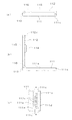
次に、添付図面を参照して本発明の実施形態について詳細に説明する。図1乃至図3は本発明に係る一実施形態の携帯型電子機器の外観を示す概略斜視図、図4は本実施形態の使用状態を示す概略斜視図、図5(a)は表部材112が倒伏姿勢にあるときの本体110の側面図、図5(b)は表部材112が起立姿勢にあるときの本体110の側面図、図5(c)は後述する保持手段による係合状態を示す拡大部分横断面図である。
Next, embodiments of the present invention will be described in detail with reference to the accompanying drawings. 1 to 3 are schematic perspective views showing an appearance of a portable electronic device according to an embodiment of the present invention, FIG. 4 is a schematic perspective view showing a use state of the embodiment, and FIG. 5B is a side view of the
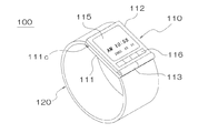
この実施形態の携帯型電子機器100は、本体110と、この本体110に接続されたバンド120とを有する。本体110は、基部材111と、この基部材111に対して起伏可能(開閉可能)に構成された表部材112とを備えている。図示例では、基部材111と表部材112とはヒンジ部113によって相互に回動可能に構成されている。表部材112の回動範囲は本実施形態では90程度で充分であるが、180度まで回動可能に構成されていてもよい。本実施形態において表部材112の起立姿勢が基部材111に対して約90度程度の角度差を有する姿勢であるものとして以下説明するが、本発明の起立姿勢としては、本実施形態の姿勢に限定されるものではなく、表部材112が開き、後述する撮像手段が外部を撮影可能な状態となっていれば、如何なる姿勢であっても構わない。
The portable
本体110は、金属、プラスチックなどの適宜の素材で構成されたケーシングを備えている。一方、バンド120は、通常の腕時計用バンドと同様のもので構成できる。したがって、バンド120は、革、人工皮革、金属、プラスチックなどの種々の素材で構成することができる。また、美錠、フックその他の連結具や開閉具など、バンド120を人体に装着したり取り外したりするための各種の締結具を備えていてもよい。なお、図面上はバンド120を細部を省略した状態で模式的に描いてある。
The
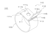
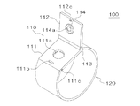
表部材112の内面、すなわち、表部材112が倒伏姿勢にあるときに基部材111に対向する面には、図3に示すように撮像手段114が設けられている。この撮像手段114は、後述するようにCCDカメラなどで構成することができる。撮像手段114は、表部材112の内面上に開口する光学開口114aを有する。また、撮像手段114の光軸は、表部材112の内面と交差する方向、図示例では垂直方向に設定されている。さらに、図示例では、撮像手段114が表部材112の内面からやや突出するように構成されているのに対応して、基部材111の内面に撮像手段114を収容する凹部111aが形成されている。この凹部111aに撮像手段114が収容されるように構成することで、本体110を薄く形成することができる。
An imaging means 114 is provided on the inner surface of the
表部材112の外面には表示手段115の表示面が設けられている。この表示手段115は後述するように液晶表示体やエレクトロルミネッセンス表示体などの画像表示体で構成することができ、このような各種の画像表示体において上記の表示面は画像を表示することができる表示画面である。また、表部材112の外面には本体操作部116が形成されている。この本体操作部116には、押圧ボタンなどの外部操作部材が配置されている。各種の操作を可能にするために、本体操作部116には複数の外部操作部材が配列されていることが好ましい。なお、図示のように表部材112の外面上に構成された本体操作部116の代わりに、本体110の側面部に突出形成されたリュウズや押圧ボタンを用いても構わない。
A display surface of the display means 115 is provided on the outer surface of the
本実施形態では、図1及び図5(a)に示すように、表部材112が基部材111に重なった姿勢、すなわち表部材112が倒伏姿勢にあるときには、表示手段115が時刻などの時間情報を表示する腕時計として用いることができる。もちろん、このような構成に限らず、本実施形態において上記時間情報以外の任意の情報(一般情報)を表示するように構成してもよい。また、図2、図3及び図5(b)に示すように、基部材111に対して表部材112が開いた姿勢、すなわち表部材112を起立姿勢にすることにより、光学開口114aが外部に露出するので、撮像手段114で外部の撮影対象を撮影可能な撮像装置として用いることができる。このとき、本体操作部116内の所定の外部操作部材を操作することにより、絞りなどの撮影条件を設定したり、撮像手段114のシャッタを切ったりすることができるように構成できる。
In this embodiment, as shown in FIG. 1 and FIG. 5A, when the
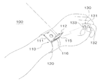
本実施形態は、図4に示すように、撮像操作手段130を本体110とは別体に設けることができる。この撮像操作手段130は、撮像手段114を操作するためのものである。撮像操作手段130には装着部131が設けられている。この装着部131は適宜の場所に撮像操作手段130を装着するためのものである。図示例では、操作部131は指に挿通可能となるように円筒状に構成されている。操作部131はリング(環)状に構成されていてもよい。また、撮像操作手段130は、少なくとも一つの外部操作部材132を含む。図示例では、外部操作部材132は例えば撮像手段114により撮影するためのシャッタボタンである。
In the present embodiment, as shown in FIG. 4, the imaging operation means 130 can be provided separately from the
また、この撮像操作手段130には、上記外部操作部材132とは別の外部操作部材133も設けられている。この外部操作部材133は、例えば、本体の動作モードを切り換えるためのモード切換操作を行うためのものである。より具体的には、外部操作部材133によって、表示手段115の表示モードを切り換える操作、或いは、本体110の表部材112の開閉状態を自動で行うことができるように構成する場合には本体の開閉状態(表部材112の倒伏姿勢と起立姿勢)を切り換える操作、が可能となるように構成することが好ましい。
The imaging operation means 130 is also provided with an
なお、外部操作部材133を操作することによって後述する保持手段を解除することができるように構成するだけでも構わない。また、操作性を向上させるために、外部操作部材133を、単なる押圧ボタンではなく、スライドスイッチやジョイスティックのような、スライド方向や傾動方向などの操作方向を選択可能かつ当該操作方向を検出可能な多機能操作部材として構成することが望ましい。さらに、図示例では外部操作部材132,133は操作部131の側面部分に形成されているが、外部操作部材は操作部131の外周面のいずれに形成されていてもよく、例えば、操作部131の内面部分(手の内側に配置される部分)に外部操作部材を設けても構わない。
It should be noted that the holding means described later may be released by operating the
本実施形態では、上記本体110の本体操作部116に設けられた外部操作部材によって撮像手段114を操作するようにしてもよく、また、上記の撮像操作手段130を用いて撮像手段114を操作するように構成してもよい。後者の場合には、本体操作部116は、撮像手段114の操作以外の本体110の機能(時刻調整機能、アラーム報知機能など)を選択したり動作させたりするために用いられるように構成されていてもよい。
In the present embodiment, the
上記本体110には、図1に示す表部材112の倒伏姿勢を保持するための保持手段を備えている。この保持手段は、表部材112の倒伏姿勢を保持できるものであれば如何なる構成となっていても構わないが、図示例の場合、基部材111と表部材112とが相互に係合した状態を保持するように構成されている。より具体的には、図2乃至図4に示すように、基部材111の内面には開口部111bが設けられ、表部材112には突起112cが設けられ、表部材112が倒伏姿勢になると、上記の開口部111bを通して突起112cが基部材111の内部に挿入され、この状態で突起112cが基部材111に係合保持されるように構成されている。
The
図5(c)は突起112cが基部材111に係合保持された状態を示すものである。基部材111には、基部材111の側部において出没自在に設けられた外部操作部111cを外端部として備えた係合部材111dが配置されている。この係合部材111dの内端部は、上記開口部111bの内側において開口部111bを通して挿入された突起112cに係合するように構成されている。突起112cは図2乃至図4及び図5(a)に示すように、先端部が拡大した形状(鉤形状或いは茸形状)を有し、この先端部に係合部材111dの内端部が係合するようになっている。係合部材111dは内部に配置されたコイルバネなどの弾性部材111eにより外部操作部111cが基部材111の側部から突出する方向に付勢されている。図示例では、一対の外部操作部111cが基部材111の両側部において出没自在となるように、一対の係合部材111dが設けられている。そして、一方の係合部材111dの内端部と他方の係合部材111dの外部操作部111cとの間と、他方の係合部材111dと一方の係合部材111dの外部操作部111cとの間に、上記弾性部材111eがそれぞれ配置されている。
FIG. 5C shows a state in which the
本実施形態において、表部材112を基部材111に重ねるようにして表部材112を倒伏姿勢にすると、突起112cが開口部111b内に挿入され、突起112cの先端部によって係合部材111dの内端部が弾性部材111eを圧縮させながら移動させられ、やがてスナップ的に突起112の先端部が係合部材111dに係合し、保持されるため、図1に示す状態では、自然に表部材112が開いてしまうといったことが防止され、通常の腕時計として何ら支障なく用いることができる。
In the present embodiment, when the
上記の倒伏姿勢において、基部材111の側部に突出している外部操作部111cを押圧すると、弾性部材111eが圧縮されて係合部材111dの内端部が突起112cの先端部から外れるため、表部材112を起立姿勢になるように開くことが可能になる。ここで、ヒンジ部113などにトーションスプリングなどの弾性部材を内蔵させておくことなどにより、表部材112が起立姿勢となる方向に常時付勢力が及ぼされるように構成することが好ましい。このようにすると、外部操作部111cを押圧して係合状態を解除するだけで、表部材112が上記付勢力によって自動的に開き、上述の起立姿勢となるように構成することができる。
In the above lying posture, when the
図6は、上記実施形態の内部構成の概略を示す構成ブロック図である。本体110には、MPU(マイクロプロセッサユニット)などで構成される中央制御部110Xと、計時機能を有し時間情報を出力する時計回路部110Yと、撮像手段114の画像処理を行う画像処理部110Zとを備えている。画像処理部110Zには、画像処理時に用いる画像メモリ110Wが接続されている。撮像手段114には、レンズ114Aやシャッタ若しくは光学絞り114Bなどを含む撮像光学系と、この撮像光学系の背後に配置されたCCDなどの撮像素子114Cとを備えている。撮像素子114Cは画像処理部110Zに撮像データを出力する。中央制御部110Xには、さらに、上記本体操作部116及び上記表示手段115を駆動する表示駆動部115Dが接続されている。ここで、上記撮像操作手段130が設けられる場合には、中央制御部110Xに操作信号入力部110Vが接続される。
FIG. 6 is a configuration block diagram showing an outline of the internal configuration of the embodiment. The
中央制御部110Xは、時計回路部110Yに時計制御信号を出力し、時計回路部110Yの制御(時刻修正、時間計測などの制御)を行う。また、中央制御部110Xは、時計回路部110Yから出力される時間情報(時刻など)を受けて表示駆動回路115Dに表示制御信号を送る。表示駆動回路115Dは上記表示制御信号に基づいて駆動信号を表示手段115に出力し、表示手段115は所定の時間情報を表示するようになっている。
The
さらに、中央制御部110Xは、撮像手段114のシャッタ若しくは光学絞り114Bに撮像制御信号を送り、上記の本体操作部116や撮像操作手段130などから送られる操作信号に応じて所定のタイミングでシャッタを駆動したり、光学絞りを調整したりするように構成されている。また、中央制御部110Xは画像処理部110Zを制御して画像処理を実行するとともに、画像処理部110Zにて形成された画像データに基づいて表示駆動部115Dを制御する。これによって、表示手段115にファインダ画像を出力したり、撮影画像を出力したりすることが可能になる。また、画像データを画像メモリ110Wに記録することもできる。
Further, the
中央制御部110Xは、表示駆動部115Dに出力する表示制御信号としての、時計回路部110Yから出力された時間情報に基づく時間表示信号と、画像処理部110Zから出力された画像情報に基づく画像表示信号とを状況に応じて適宜に切り換えることによって、表示手段115にて表示される表示情報を切り換えることができる。例えば、本体操作部116や撮像操作手段130に対する適宜の操作によって上記表示情報が切り換えられるように構成してもよく、また、図示しないセンサなどによって表部材112が倒伏姿勢にあるか起立姿勢にあるかを検出し、その検出結果に応じて上記表示情報が切り換えられるように構成してもよい。すなわち、表部材112が倒伏姿勢にあるときには時間情報その他の一般情報を表示し、起立姿勢にあるときには撮像情報を表示するように構成する。より具体的には、例えば、上記保持手段を構成する外部操作部111cが押圧操作されると上記表示情報を時刻やタイマー時間などの時間情報その他の一般情報に切り換え、上記係合部材111dが突起112cに係合保持されると上記表示情報を上記ファインダ画像や撮像画像、或いは、撮像条件設定状況や最適撮像条件などの撮像情報に切り換える。
The
撮像操作手段130には、外部操作部材132の操作状態に応じて操作信号を出力する信号変換部130Xと、この信号変換部130Xが出力する操作信号を出力する操作信号出力部130Yとが設けられる。操作信号出力部130Yは、操作信号を適宜の態様で本体110に設けられた操作信号入力部110Vに送信し、操作信号入力部110Vは、受信した操作信号を上記中央制御部110Xに出力する。ここで、操作信号出力部130Yから操作信号入力部110Vに無線で操作信号が伝送されるように構成する場合には、ブルートゥースなどの近距離無線通信により、所定のプロトコルで通信が行われる。この場合には、操作信号出力部130Yは送信回路を含み、操作信号入力部110Vは受信回路を含む。また、操作信号出力部130Yと操作信号入力部110Vの間にコードなどの配線が接続される場合には、有線方式で上記操作信号が伝送される。
The imaging operation means 130 is provided with a
以上説明した本実施形態によれば、表部材112を倒伏姿勢とすることによって通常の腕時計などの携帯機器として用いることができるとともに、撮像手段114の光学開口114aが表部材112の内面上にあるので、外観デザインが制約されることが少なくなり、また、表部材によって保護された状態となっているので、撮像手段114の汚損などを防止することができる。一方、表部材112を起立姿勢とすることによって撮像手段114の光学開口114aを露出させ、外部の撮像対象を適宜に撮影することができる。このとき、図4に示す姿勢で表部材112の外面に形成された表示手段115の表示面にファインダ画像を表示することによって、表部材112の内面に形成された撮像手段114の光学開口114aを通して撮影することにより、撮像手段114の光軸と、使用者の視線とをほぼ同一方向に設定することが可能になるので、撮影範囲の調整がしやすくなるなど、きわめて容易に撮影を行うことができる。
According to this embodiment described above, the
また、上記撮像操作手段130を設けることによって、本体110の本体操作部116を操作しなくても撮影を行うことができるため、シャッタボタンを押圧するときの押圧力による撮像手段114の位置ずれが発生しにくくなることから、撮影画像のぶれを防止することができる。ここで、撮像操作手段130は図4に示すように指に装着されるため、操作自体がきわめて容易に行えるとともに、図4に示すように本体110を装着した手に撮像操作手段130を装着することができることから、片手で全ての処理を行うことができることから、操作がさらに容易になるとともに迅速にシャッターを切ることができるため、シャッターチャンスを逃すことがなくなるという利点もある。
In addition, since the
尚、本発明の携帯型電子機器は、上述の図示例にのみ限定されるものではなく、本発明の要旨を逸脱しない範囲内において種々変更を加え得ることは勿論である。例えば、上記実施形態では、表部材112が倒伏姿勢にあるときには腕時計として用いることができるように構成されているが、本体110に時計機能が併設されている場合に限らず、撮像機能のみ、或いは、撮像機能に加えて撮像機能や時計機能以外の他の機能、例えば、計算機能、心拍計数機能、通信機能などを備えたものであってもよい。また、上記のように本体を腕に装着する場合に限らず、掌や腰などに装着するように構成してもよい。
It should be noted that the portable electronic device of the present invention is not limited to the illustrated examples described above, and it is needless to say that various modifications can be made without departing from the gist of the present invention. For example, in the above-described embodiment, the
100…携帯型電子機器、110…本体、111…基部材、111b…開口部、111c…外部操作部、111d…係合部材、111e…弾性部材、112…表部材、113…ヒンジ部、114…撮像手段、114a…光学開口、115…表示手段、116…本体操作部、120…バンド、130…撮像操作手段、131…装着部、132,133…外部操作部材
DESCRIPTION OF
Claims (12)
前記本体は、基部材と、前記基部材の表面に対して起伏可能に構成された表部材とを有し、
前記撮像手段は、前記表部材が倒伏姿勢にあるときに前記基部材に対向する前記表部材の内面上に光学開口を有することを特徴とする携帯型電子機器。 A main body provided with imaging means, and a band connected to the main body,
The main body includes a base member and a front member configured to be able to undulate with respect to the surface of the base member,
The portable electronic device, wherein the imaging means has an optical opening on an inner surface of the front member facing the base member when the front member is in a lying posture.
前記本体は、基部材と、前記基部材の表面に対して起伏可能に構成された表部材とを有し、
前記表部材には撮像手段が設けられ、
前記撮像手段を操作する撮像操作手段が前記本体と別体に構成されていることを特徴とする携帯型電子機器。 A main body and a band connected to the main body;
The main body includes a base member and a front member configured to be able to undulate with respect to the surface of the base member,
The front member is provided with imaging means,
A portable electronic device, wherein an imaging operation means for operating the imaging means is configured separately from the main body.
11. The portable electronic device according to claim 8, wherein operation information of the imaging operation unit is transmitted to the main body via a wiring.
Priority Applications (1)
| Application Number | Priority Date | Filing Date | Title |
|---|---|---|---|
| JP2003353655A JP2005123711A (en) | 2003-10-14 | 2003-10-14 | Portable electronic apparatus |
Applications Claiming Priority (1)
| Application Number | Priority Date | Filing Date | Title |
|---|---|---|---|
| JP2003353655A JP2005123711A (en) | 2003-10-14 | 2003-10-14 | Portable electronic apparatus |
Publications (1)
| Publication Number | Publication Date |
|---|---|
| JP2005123711A true JP2005123711A (en) | 2005-05-12 |
Family
ID=34611881
Family Applications (1)
| Application Number | Title | Priority Date | Filing Date |
|---|---|---|---|
| JP2003353655A Withdrawn JP2005123711A (en) | 2003-10-14 | 2003-10-14 | Portable electronic apparatus |
Country Status (1)
| Country | Link |
|---|---|
| JP (1) | JP2005123711A (en) |
Cited By (6)
| Publication number | Priority date | Publication date | Assignee | Title |
|---|---|---|---|---|
| CN103235476A (en) * | 2013-05-06 | 2013-08-07 | 苏州百纳思光学科技有限公司 | Minicamera and flash lamp device for intelligent watches |
| CN103685953A (en) * | 2013-12-06 | 2014-03-26 | 宇龙计算机通信科技(深圳)有限公司 | Shooting device, mobile terminal and watch |
| JP2018005211A (en) * | 2015-12-01 | 2018-01-11 | 孝郎 林 | Wrist-mounted device with imaging function and posture change device |
| JP2018004713A (en) * | 2016-06-27 | 2018-01-11 | 孝郎 林 | Wrist device with imaging function |
| CN110139022A (en) * | 2018-09-29 | 2019-08-16 | 广东小天才科技有限公司 | A kind of camera control method and wearable device, storage medium |
| CN110139044A (en) * | 2018-09-29 | 2019-08-16 | 广东小天才科技有限公司 | A kind of information acquisition method and wearable device based on wearable device |
-
2003
- 2003-10-14 JP JP2003353655A patent/JP2005123711A/en not_active Withdrawn
Cited By (6)
| Publication number | Priority date | Publication date | Assignee | Title |
|---|---|---|---|---|
| CN103235476A (en) * | 2013-05-06 | 2013-08-07 | 苏州百纳思光学科技有限公司 | Minicamera and flash lamp device for intelligent watches |
| CN103685953A (en) * | 2013-12-06 | 2014-03-26 | 宇龙计算机通信科技(深圳)有限公司 | Shooting device, mobile terminal and watch |
| JP2018005211A (en) * | 2015-12-01 | 2018-01-11 | 孝郎 林 | Wrist-mounted device with imaging function and posture change device |
| JP2018004713A (en) * | 2016-06-27 | 2018-01-11 | 孝郎 林 | Wrist device with imaging function |
| CN110139022A (en) * | 2018-09-29 | 2019-08-16 | 广东小天才科技有限公司 | A kind of camera control method and wearable device, storage medium |
| CN110139044A (en) * | 2018-09-29 | 2019-08-16 | 广东小天才科技有限公司 | A kind of information acquisition method and wearable device based on wearable device |
Similar Documents
| Publication | Publication Date | Title |
|---|---|---|
| JP5029012B2 (en) | Electronics | |
| JP4828221B2 (en) | Digital camera | |
| JP3948387B2 (en) | Digital camera and mobile phone device with digital camera | |
| JP5093968B2 (en) | camera | |
| US20170223236A1 (en) | Wearable Camera Apparatus | |
| WO2015194084A1 (en) | Information processing device, information processing system, and information processing method and program | |
| US20200348627A1 (en) | Wrist-Worn Device with One or More Cameras and a Comfortable Arm Posture During Imaging | |
| US20040165106A1 (en) | Digital camera | |
| US20050052537A1 (en) | Mounted imaging apparatus | |
| JP2005123711A (en) | Portable electronic apparatus | |
| KR101855790B1 (en) | Control watch for ominidirectional camera | |
| JP4662902B2 (en) | Shooting system | |
| US20220311920A1 (en) | Image pickup apparatus | |
| US6842193B2 (en) | Electronic camera | |
| CN104780298B (en) | Camera system without image display function | |
| CN115209013A (en) | Imaging device, control method for imaging device, and recording medium | |
| JP2007017746A (en) | Imaging system, camera main body and lens | |
| JP2003018443A (en) | Digital camera | |
| JP6657929B2 (en) | Portable device, system, control method, and program | |
| JP2006157967A (en) | Digital camera and portable telephone apparatus with the digital camera | |
| JP2004192167A (en) | Portable terminal and information input device | |
| JP3097550U (en) | Conversion lens device for mobile terminal with camera | |
| JP2007279396A (en) | Camera system | |
| JP4383370B2 (en) | Imaging device | |
| JP2005110114A (en) | Portable apparatus |
Legal Events
| Date | Code | Title | Description |
|---|---|---|---|
| A300 | Application deemed to be withdrawn because no request for examination was validly filed |
Free format text: JAPANESE INTERMEDIATE CODE: A300 Effective date: 20070109 |