JP2005113992A - Moving agricultural machine - Google Patents

Moving agricultural machine Download PDF

Info

Publication number
JP2005113992A
JP2005113992A JP2003347249A JP2003347249A JP2005113992A JP 2005113992 A JP2005113992 A JP 2005113992A JP 2003347249 A JP2003347249 A JP 2003347249A JP 2003347249 A JP2003347249 A JP 2003347249A JP 2005113992 A JP2005113992 A JP 2005113992A
Authority
JP
Japan
Prior art keywords
case
gear
transmission
shaft
hydraulic
Prior art date
Legal status (The legal status is an assumption and is not a legal conclusion. Google has not performed a legal analysis and makes no representation as to the accuracy of the status listed.)
Pending
Application number
JP2003347249A
Other languages
Japanese (ja)
Inventor
Hirofumi Aizawa
宏文 相沢
Minoru Ueda
実 上田
Kenichi Ide
健一 井手
Tadasato Kataoka
正覚 片岡
Current Assignee (The listed assignees may be inaccurate. Google has not performed a legal analysis and makes no representation or warranty as to the accuracy of the list.)
Yanmar Agribusiness Co Ltd
Original Assignee
Seirei Industry Co Ltd
Priority date (The priority date is an assumption and is not a legal conclusion. Google has not performed a legal analysis and makes no representation as to the accuracy of the date listed.)
Filing date
Publication date
Application filed by Seirei Industry Co Ltd filed Critical Seirei Industry Co Ltd
Priority to JP2003347249A priority Critical patent/JP2005113992A/en
Publication of JP2005113992A publication Critical patent/JP2005113992A/en
Pending legal-status Critical Current

Links

Images

Classifications

    • FMECHANICAL ENGINEERING; LIGHTING; HEATING; WEAPONS; BLASTING
    • F16ENGINEERING ELEMENTS AND UNITS; GENERAL MEASURES FOR PRODUCING AND MAINTAINING EFFECTIVE FUNCTIONING OF MACHINES OR INSTALLATIONS; THERMAL INSULATION IN GENERAL
    • F16HGEARING
    • F16H57/00General details of gearing
    • F16H57/04Features relating to lubrication or cooling or heating
    • F16H57/042Guidance of lubricant
    • F16H57/0421Guidance of lubricant on or within the casing, e.g. shields or baffles for collecting lubricant, tubes, pipes, grooves, channels or the like

Abstract

<P>PROBLEM TO BE SOLVED: To make a hydraulic operating means accurately function by securing appropriate function of an operating fluid. <P>SOLUTION: A gear case with a built-in low-speed rotating gear is continuously provided to a transmission case with a built-in high-speed rotating gear, and lubricating oil is supplied into both the cases, and a hydraulic operating means is connected to the gear case for communication through a feeding oil passage, and the transmission case is connected to the hydraulic operating means for communication through a return oil passage. The lubricating oil supplied into both of the transmission case and the gear case is returned as the operating fluid to circulate the gear case, the feeding oil passage, the hydraulic operating means, the return oil passage, the transmission case and the gear case again in this order. <P>COPYRIGHT: (C)2005,JPO&NCIPI

Description

本発明は、果樹園に薬剤を散布する自走型スピードスプレーヤ等の移動農機に関する。   The present invention relates to a mobile farm machine such as a self-propelled speed sprayer that sprays medicines in an orchard.

従来、移動農機の一形態として、ミッションケースをオイルタンクとして、同ミッションケースに油圧回路を介して油圧作動手段としてのパワーステアリングシリンダを接続して、同ミッションケース内の潤滑油を作動油として利用するようにしたものがある(例えば、特許文献1参照)。   Conventionally, as a form of mobile farming machine, the mission case is used as an oil tank, and a power steering cylinder as hydraulic operating means is connected to the mission case via a hydraulic circuit, and the lubricating oil in the mission case is used as hydraulic oil. There is something which is made to do (for example, refer to patent documents 1).

そして、パワーステアリングシリンダを制御するパワーステアリングバルブを、エンジンやラジエータを冷却する冷却ファンの冷却風路上に配置すると共に、同パワーステアリングバルブ内に油圧回路中の作動油を循環させて、同作動油を冷却するようにしている。
特開平10−338042号公報
A power steering valve for controlling the power steering cylinder is disposed on the cooling air passage of the cooling fan for cooling the engine and the radiator, and the hydraulic oil in the hydraulic circuit is circulated in the power steering valve. To cool down.
Japanese Patent Laid-Open No. 10-338042

ところが、上記した移動農機では、冷却ファンの冷却風路上にパワーステアリングバルブを配置しなければならないために、エンジン、ラジエータ、冷却ファン及びパワーステアリングバルブ等の配設位置が制約されるという不具合がある。   However, in the above-mentioned mobile agricultural machine, since the power steering valve must be arranged on the cooling air passage of the cooling fan, there is a problem that the arrangement positions of the engine, the radiator, the cooling fan, the power steering valve, and the like are restricted. .

そこで、本発明では、高速回転ギヤを内蔵するミッションケースに、低速回転ギヤを内蔵するギヤケースを連通連設して、両ケース内に潤滑油を供給すると共に、ギヤケースに送り出し油路を介して油圧作動手段を連通連結し、かつ、同油圧作動手段に戻し油路を介してミッションケースを連通連結したことを特徴とする移動農機を提供するものである。   Therefore, in the present invention, a gear case incorporating a low-speed rotating gear is connected in communication with a transmission case incorporating a high-speed rotating gear, and lubricating oil is supplied into both cases and is supplied to the gear case via a hydraulic passage through the oil passage. It is an object of the present invention to provide a mobile agricultural machine characterized in that operating means are connected in communication and a transmission case is connected to the hydraulic operating means via a return oil passage.

また、本発明は、以下の構成にも特徴を有する。   The present invention is also characterized by the following configuration.

(1)ギヤケースは、ミッションケース内に供給された潤滑油の油面よりも低位置に配置したこと。   (1) The gear case is disposed at a position lower than the oil level of the lubricating oil supplied in the mission case.

(2)ギヤケースにアクスルケースを連通連設して、同アクスルケースと油圧作動手段との間に送り出し油路を介設すると共に、同送り出し油路にフィルタを設けたこと。   (2) An axle case is provided in communication with the gear case, a feed oil passage is provided between the axle case and the hydraulic operating means, and a filter is provided in the feed oil passage.

(1)請求項1記載の本発明では、高速回転ギヤを内蔵するミッションケースに、低速回転ギヤを内蔵するギヤケースを連通連設して、両ケース内に潤滑油を供給すると共に、ギヤケースに送り出し油路を介して油圧作動手段を連通連結し、かつ、同油圧作動手段に戻し油路を介してミッションケースを連通連結している。   (1) According to the first aspect of the present invention, a transmission case having a high-speed rotation gear is connected to a gear case having a low-speed rotation gear, and lubricating oil is supplied into both cases and is sent to the gear case. The hydraulic operation means is connected in communication through the oil passage, and the transmission case is connected in communication through the return oil passage to the hydraulic operation means.

このようにして、ミッションケースとギヤケースの両ケース内に供給した潤滑油を、作動油としてギヤケース→送り出し油路→油圧作動手段→戻し油路→ミッションケース→ギヤケースに戻すようにしている。   In this way, the lubricating oil supplied into both the transmission case and the gear case is returned to the gear case → the delivery oil passage → the hydraulic operation means → the return oil passage → the transmission case → the gear case as the working oil.

この際、高速回転ギヤを内蔵するミッションケース内の潤滑油を、油圧作動手段に作動油として直接送り出すのではなく、低速回転ギヤを内蔵するギヤケースを通して油圧作動手段に作動油として送り出すようにしているため、ミッションケース内の潤滑油をギヤケース内にて低温化した後に油圧作動手段に作動油として送り出すことができて、同作動油の適正機能を確保することができて、油圧作動手段を精度良く機能させることができる。   At this time, the lubricating oil in the transmission case incorporating the high-speed rotating gear is not directly sent as hydraulic oil to the hydraulic operating means, but is sent as hydraulic oil to the hydraulic operating means through the gear case incorporating the low-speed rotating gear. Therefore, the lubricating oil in the transmission case can be sent out to the hydraulic operating means as the operating oil after the temperature in the gear case is lowered, and the proper function of the hydraulic oil can be secured, and the hydraulic operating means can be accurately Can function.

しかも、冷却ファンの冷却風路に関わりなく構成部材を配置することができるため、同構成部材の配設位置が制約を受けるという不具合が生じない。   In addition, since the constituent members can be arranged regardless of the cooling air path of the cooling fan, there is no problem that the arrangement position of the constituent members is restricted.

(2)請求項2記載の本発明では、ギヤケースは、ミッションケース内に供給された潤滑油の油面よりも低位置に配置している。   (2) In the present invention according to claim 2, the gear case is disposed at a position lower than the oil level of the lubricating oil supplied into the transmission case.

このようにして、ギヤケースをミッションケース内に供給された潤滑油の油面よりも低位置に配置しているため、同ギヤケース内を潤滑油により満たすことができて、同ギヤケースから油圧作動手段に送り出される作動油内に空気が混入するのを防止することができる。   In this way, since the gear case is arranged at a position lower than the oil level of the lubricating oil supplied in the transmission case, the gear case can be filled with the lubricating oil, and the gear case can be used as hydraulic operating means. It is possible to prevent air from being mixed into the hydraulic fluid to be sent out.

従って、この点からも、作動油の適正機能を確保することができて、油圧作動手段を精度良く機能させることができる。   Therefore, also from this point, the proper function of the hydraulic oil can be ensured, and the hydraulic operation means can be functioned with high accuracy.

(3)請求項3記載の本発明では、ギヤケースにアクスルケースを連通連設して、同アクスルケースと油圧作動手段との間に送り出し油路を介設すると共に、同送り出し油路にフィルタを設けている。   (3) In the present invention described in claim 3, an axle case is connected in communication with the gear case, a feed oil passage is provided between the axle case and the hydraulic operation means, and a filter is provided in the feed oil passage. Provided.

このようにして、ギヤケースに連通連設したアクスルケースから送り出し油路を通して油圧作動手段に作動油を送り出すようにすると共に、同送り出し油路にフィルタを設けているため、油圧作動手段に送り出される作動油の低温化を良好に確保することができると共に、かかる作動油中の不純物はフィルタを通して濾過して、不純物の含まれない作動油を油圧作動手段に送り出すことができる。   In this way, hydraulic oil is sent from the axle case communicating with the gear case to the hydraulic operating means through the delivery oil passage, and a filter is provided in the delivery oil passage so that the operation is sent to the hydraulic operation means. The temperature of the oil can be ensured well, and impurities in the hydraulic oil can be filtered through a filter, and the hydraulic oil not containing impurities can be sent to the hydraulic operating means.

従って、この点からも、作動油の適正機能をより一層確保することができて、油圧作動手段を精度良く機能させることができる。   Therefore, also from this point, the proper function of the hydraulic oil can be further ensured, and the hydraulic operation means can be functioned with high accuracy.

以下に、本発明に係る最良の実施の形態を、図面を参照しながら説明する。   The best mode for carrying out the present invention will be described below with reference to the drawings.

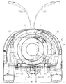
図1〜図4に示すAは、本発明に係る移動農機としてのスピードスプレーヤであり、同スピードスプレーヤAは、機体フレーム1上において、前部に運転部2を配設し、同運転部2の左側方位置から後方位置にかけて薬液タンク部3を配設し、同薬液タンク部3の後方位置に原動機部4とミッション部5と両者を連動連結する伝動機構部6とを配設し、これらの後方位置に上記伝動機構部6と連動連結した薬液散布部7を配設している。Mはオペレータである。   A shown in FIGS. 1 to 4 is a speed sprayer as a mobile agricultural machine according to the present invention. The speed sprayer A is provided with a driving unit 2 at the front on the machine body frame 1, and the driving unit 2. The chemical liquid tank unit 3 is disposed from the left side position to the rear position of the motor, and the prime mover unit 4 and the transmission unit 5 and the transmission mechanism unit 6 that interlocks the two are disposed at the rear position of the chemical liquid tank unit 3. A chemical solution spraying portion 7 that is linked to the transmission mechanism portion 6 is disposed at the rear position. M is an operator.

そして、図1〜図4に示すように、機体フレーム1の前部にフロントアクスル部8を介して左右一対の前車輪9,9を取り付ける一方、前記ミッション部5の後部にリヤアクスル部10を介して左右一対の後車輪11,11を取り付け、上記ミッション部5にドライブシャフト12を介してフロントアクスル部8を連動連結して、前・後車輪9,9,11,11による四輪駆動が行えるようにしている。   1 to 4, a pair of left and right front wheels 9, 9 are attached to the front portion of the body frame 1 via a front axle portion 8, while a rear axle portion 10 is attached to the rear portion of the transmission portion 5. A pair of left and right rear wheels 11 and 11 are attached to the transmission unit 5 and the front axle 8 is linked to the transmission unit 5 via the drive shaft 12 so that four-wheel drive can be performed by the front and rear wheels 9, 9, 11, and 11. I am doing so.

〔機体フレーム1の説明〕
機体フレーム1について説明すると、同機体フレーム1は、図1〜図4に示すように、主として運転部2とフロントアクスル部8とを支持する前部機体フレーム形成体15と、主として原動機部4とミッション部5と伝動機構部6と薬液散布部7とを支持する後部機体フレーム形成体16とから形成しており、各前・後部機体フレーム形成体15,16は、前後方向に伸延する四角形枠状に形成している。
[Description of Airframe Frame 1]
The airframe frame 1 will be described. The airframe frame 1 includes, as shown in FIGS. 1 to 4, a front airframe frame forming body 15 that mainly supports the operating portion 2 and the front axle portion 8, and a prime mover portion 4. Each of the front and rear machine frame forming bodies 15 and 16 is formed by a rectangular frame extending in the front-rear direction. The rear machine frame forming body 16 supports the transmission unit 5, the transmission mechanism unit 6, and the chemical solution spraying unit 7. It is formed in a shape.

〔運転部2の説明〕
次に、運転部2について説明すると、同運転部2は、図1及び図2に示すように、前部機体フレーム形成体15の前部に立設したステアリングポスト17にホイール支軸18を介してステアリングホイール19を取り付け、同ステアリングホイール19の後方位置に運転席支持枠体20を介して運転席21を配置している。
[Description of driving unit 2]
Next, the driving unit 2 will be described. As shown in FIGS. 1 and 2, the driving unit 2 includes a wheel post 18 on a steering post 17 erected on the front part of the front body frame forming body 15. A steering wheel 19 is attached, and a driver's seat 21 is disposed behind the steering wheel 19 via a driver's seat support frame 20.

〔薬液タンク部3の説明〕
次に、薬液タンク部3について説明すると、同薬液タンク部3は、図1及び図2に示すように、運転部2の左側方から後方にわたって平面視略L字状に形成したタンク本体22を具備しており、同タンク本体22の天井部に薬液供給用開閉蓋体23を開閉自在に取り付けている。
[Explanation of chemical tank part 3]
Next, the chemical liquid tank unit 3 will be described. As shown in FIGS. 1 and 2, the chemical liquid tank unit 3 includes a tank body 22 formed in a substantially L shape in plan view from the left side to the rear side of the operating unit 2. A chemical solution supply opening / closing lid 23 is attached to the ceiling of the tank body 22 so as to be freely opened and closed.

〔原動機部4の説明〕
次に、原動機部4について説明すると、同原動機部4は、図1〜6に示すように、前後方向に伸延して前記後部機体フレーム形成体16の一部を形成する左右一対の機体フレーム形成片25,25間にエンジンマウントステー26を介してエンジン27を搭載し、同エンジン27の左側方位置にラジエータ支持枠体28を介してラジエータ29を配設すると共に、同エンジン27の右側後方位置にラジエータ支持枠体28を介してエアクリーナ30を配設している。
[Explanation of prime mover part 4]
Next, the prime mover part 4 will be described. As shown in FIGS. 1 to 6, the prime mover part 4 extends in the front-rear direction and forms a part of the rear fuselage frame formation body 16 to form a pair of left and right machine body frames. An engine 27 is mounted between the pieces 25 and 25 via an engine mount stay 26, and a radiator 29 is disposed on the left side of the engine 27 via a radiator support frame 28. Further, an air cleaner 30 is disposed via a radiator support frame 28.

また、エンジン27の上部右側方位置には、図6に示すように、薬液ポンプ31を配設しており、同薬液ポンプ31に薬液タンク部3を介して薬液散布部7を連通連結して、薬液タンク部3のタンク本体22内に貯留している薬液を薬液散布部7に圧送して、同薬液散布部7により薬液を周囲に散布することができるようにしている。   Further, as shown in FIG. 6, a chemical liquid pump 31 is disposed at the upper right side position of the engine 27, and the chemical liquid spraying section 7 is connected to the chemical liquid pump 31 via the chemical liquid tank section 3. The chemical liquid stored in the tank body 22 of the chemical liquid tank section 3 is pumped to the chemical liquid spraying section 7 so that the chemical liquid spraying section 7 can spray the chemical liquid around.

ここで、上記したエンジンマウントステー26は、図5及び図6に示すように、左右一対の機体フレーム形成片25,25間に横架しており、左右側立ち上がり壁片32,33と両立ち上がり壁片32,33の上端間に横架した支持本片34とを具備している。   Here, as shown in FIGS. 5 and 6, the engine mount stay 26 is horizontally placed between a pair of left and right body frame forming pieces 25, 25, and rises from the left and right rising wall pieces 32, 33. A supporting book piece 34 is provided between the upper ends of the wall pieces 32 and 33.

しかも、支持本片34は、一側半部(本実施形態では左側半部34a)と他側半部(本実施形態では右側半部34b)との間に高低段差を形成して、低部側である左側半部34a上にエンジンマウント35,36を介してエンジン27を搭載している。   Moreover, the support main piece 34 is formed with a step difference between one half (the left half 34a in the present embodiment) and the other half (the right half 34b in the present embodiment). The engine 27 is mounted on the left half part 34a on the side through engine mounts 35 and 36.

このようにして、エンジン27は、機体の左右中心線よりも左右いずれか一側方(本実施形態では左側方)に偏倚させて配置している。   In this way, the engine 27 is arranged so as to be biased to one of the left and right sides (the left side in the present embodiment) with respect to the left and right center line of the airframe.

そして、図5及び図6に示すように、エンジン27より後方へ突出させた駆動軸39(図19参照)と後述するクラッチ部37との間に伝動機構部6を介設しており、左側の機体フレーム形成片25に左側マウント40を介して伝動機構部6の左側下部を支持させると共に、右側機体フレーム形成片25に右側マウント41を介して伝動機構部6の右側下部を支持させている。   As shown in FIGS. 5 and 6, the transmission mechanism 6 is interposed between a drive shaft 39 (see FIG. 19) that protrudes rearward from the engine 27 and a clutch portion 37 that will be described later. The machine body frame forming piece 25 supports the lower left portion of the transmission mechanism 6 via the left mount 40, and the right machine frame forming piece 25 supports the lower right portion of the transmission mechanism section 6 via the right mount 41. .

また、図21及び図22に示すように、機体フレーム形成片25,25の後部にそれぞれ支持台115,116を設け、両支持台115,116間に前記したラジエータ支持枠体28を跨架しており、同ラジエータ支持枠体28は、左側の支持台115上に立設したラジエータ支持枠本体117と、同ラジエータ支持枠本体117の後上部と右側の支持台116との間に架設した補強枠体118とから形成している。   Further, as shown in FIGS. 21 and 22, support bases 115 and 116 are respectively provided at the rear portions of the machine body frame forming pieces 25 and 25, and the radiator support frame body 28 is straddled between the support bases 115 and 116. The radiator support frame 28 includes a radiator support frame main body 117 erected on the left support base 115, and a reinforcement frame 118 installed between the rear upper portion of the radiator support frame main body 117 and the right support base 116. Formed from.

そして、ラジエータ支持枠本体117は側面視門型に形成して、同ラジエータ支持枠体117にラジエータ29を取り付けている。   The radiator support frame main body 117 is formed in a side view portal shape, and the radiator 29 is attached to the radiator support frame body 117.

補強枠体118は、エンジン27の上部後方位置において、左右方向に伸延して、左側端部をラジエータ支持枠本体117の後上部に連結した左右伸延片119と、同左右伸延片119の右側端部より右側下方へ向けて伸延する下り傾斜片120と、同下り傾斜片120の右側端部より下方へ向けて伸延して、右側の支持台116に下端部を固定した下方伸延片121とから形成して、ラジエータ支持枠体117と補強体118とからなるラジエータ支持枠体28を、背面視略門型に形成している。   The reinforcing frame 118 extends in the left-right direction at the upper rear position of the engine 27, and the left and right extending pieces 119 having the left end connected to the rear upper portion of the radiator support frame main body 117, and the right end of the left and right extending pieces 119 A downwardly inclined piece 120 extending downward from the right side downward and a downwardly extending piece 121 extending downward from the right end of the downwardly inclined piece 120 and having the lower end fixed to the right support 116. Thus, a radiator support frame body 28 including a radiator support frame body 117 and a reinforcing body 118 is formed in a substantially portal shape in a rear view.

そして、傾斜片部としての下り傾斜片120に沿わせてエアクリーナ30を取り付け、同下り傾斜片120の近傍にエアクリーナ30の吸気部30aを配置している。   The air cleaner 30 is attached along the downward inclined piece 120 as the inclined piece, and the air intake portion 30a of the air cleaner 30 is disposed in the vicinity of the downward inclined piece 120.

このようにして、ラジエータ支持枠体117の一側部(本実施例では右側部)に形成した下り傾斜片120に沿わせてエアクリーナ30を配置しているため、同エアクリーナ30をラジエータ支持枠体28の下り傾斜片120に簡単かつ確実に取り付けることができると共に、コンパクトに配置することができる。   Thus, since the air cleaner 30 is arranged along the downward inclined piece 120 formed on one side portion (right side portion in the present embodiment) of the radiator support frame 117, the air cleaner 30 is disposed on the radiator support frame body. It can be easily and surely attached to the 28 downwardly inclined pieces 120 and can be arranged compactly.

しかも、エンジン27にエアクリーナ30を直接固定していないため、同エンジン27のメンテナンス等を行う際に、エアクリーナ30が支障となることがない。   In addition, since the air cleaner 30 is not directly fixed to the engine 27, the air cleaner 30 does not hinder the maintenance of the engine 27 or the like.

さらには、下り傾斜片120の近傍にエアクリーナ30の吸気部30aを配置しているため、同吸気部30aを通してエアクリーナ30に外気を確実に取り込むことができる。   Furthermore, since the intake portion 30a of the air cleaner 30 is disposed in the vicinity of the downward inclined piece 120, the outside air can be reliably taken into the air cleaner 30 through the intake portion 30a.

また、ラジエータ支持枠体28の一部を形成する補強枠体118は、導風体ステーを兼用しており、同補強枠体118の左右伸延片119と下方伸延片121とに、後述する薬液散布部7の一部を形成する導風体122を取付ボルト123,124,125により着脱自在に取り付けている。   Further, the reinforcing frame 118 forming a part of the radiator support frame 28 also serves as an air guide stay, and a chemical solution spray described later is applied to the left and right extending pieces 119 and the downward extending pieces 121 of the reinforcing frame 118. A wind guide body 122 forming a part of the portion 7 is detachably attached by mounting bolts 123, 124, and 125.

このようにして、補強枠体118に導風体ステーを兼用させているため、別途導風体ステーを設けることなく導風体122を確実に支持することができて、部品点数の削減と製造コストの低減とを図ることができる。   In this manner, since the reinforcing frame 118 is also used as a wind guide stay, the wind guide 122 can be reliably supported without providing a separate wind guide stay, thereby reducing the number of parts and the manufacturing cost. Can be planned.

図4中、126,127は、上下方向に開閉自在となしたカバー体としてのボンネット形成体であり、コンパクトに配置したエアクリーナ30の上方を被覆すべく円弧状に形成して、枝下作業時に枝が引っ掛かるのを極力防止することができるようにしている。   In FIG. 4, 126 and 127 are bonnet forming bodies as cover bodies that can be opened and closed in the vertical direction. The bonnet forming body is formed in an arc shape so as to cover the upper portion of the
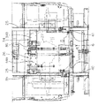
 air cleaner 30 arranged in a compact manner. It is possible to prevent it from being caught as much as possible.

〔ミッション部5の説明〕
次に、ミッション部5について説明すると、同ミッション部5は、図5〜図12に示すように、上下方向に伸延させて形成しており、前記支持本片34の前端部に沿わせて上下方向に伸延するミッション部5を左低右高の傾斜状に配設して、エンジン27の直下方位置、すなわち、支持本片34の低部側である左側半部34aの直下方位置にミッション部5の左側下部を配置すると共に、支持本片34の高部側である右側半部34bの直下方位置にミッション部5の右側上部を配置している。
[Description of Mission 5]
Next, the mission unit 5 will be described. As shown in FIGS. 5 to 12, the mission unit 5 is formed by extending in the vertical direction, and is arranged vertically along the front end portion of the support main piece 34. The mission section 5 extending in the direction is arranged in a slanted shape with a left low right height, and the mission is positioned directly below the engine 27, that is, directly below the left half 34a on the low side of the support piece 34. The lower left portion of the portion 5 is disposed, and the upper right portion of the mission portion 5 is disposed at a position directly below the right half portion 34b which is the high portion side of the support main piece 34.

そして、図8及び図9に示すように、エンジン27の偏倚させた側とは反対側(本実施形態では右側)の側方空間S内にクラッチ部37を配設すると共に、同クラッチ部37をミッション部5の右側上部に連動連設し、同クラッチ部37を後述する伝動機構部6を介してエンジン27に連動連結しており、クラッチ部37は、エンジン27の側方空間S内において、一部をエンジン27と上下方向に重合状態となしている。   As shown in FIGS. 8 and 9, the clutch portion 37 is disposed in the side space S on the side opposite to the biased side of the engine 27 (right side in the present embodiment), and the clutch portion 37 is also provided. Is coupled to the upper right side of the transmission unit 5 and the clutch unit 37 is coupled to the engine 27 via a transmission mechanism unit 6 to be described later. The clutch unit 37 is located in the side space S of the engine 27. Part of this is superposed with the engine 27 in the vertical direction.

しかも、エンジン27の側方空間Sは、クラッチ部37の配設空間と各種伝動機構の配設空間、すなわち、後述する伝動機構部6と前記薬液ポンプ31との間に介設するポンプ伝動機構38の配設空間を兼用している。   In addition, the side space S of the engine 27 is a space where the clutch portion 37 is disposed and a space where various transmission mechanisms are disposed, that is, a pump transmission mechanism which is interposed between the transmission mechanism portion 6 and the chemical pump 31 which will be described later. 38 installation spaces are also used.

また、ミッション部5は、図10〜図14に示すように、左側下部の後方にデファレンシャル部42を連動連設すると共に、同デファレンシャル部42の後方にリヤアクスル部10を連動連設している。   In addition, as shown in FIGS. 10 to 14, the mission unit 5 includes a differential portion 42 that is linked to the rear of the lower left portion, and a rear axle portion 10 that is linked to the rear of the differential portion 42.

そして、ミッション部5は、上下方向に伸延させて形成したミッションケース44を前部ケース形成体45と後部ケース形成体46とに分割して形成し、同後部ケース形成体46の右側上部に、クラッチ部37のクラッチケース本体47を後方へ突出状に一体成形する一方、後部ケース形成体46の左側下部にデファレンシャル部42のデファレンシャルケース48を後方へ突出状に一体成形して、前部ケース形成体45に、後部ケース形成体46とクラッチケース本体47とデファレンシャルケース48とを、前後方向に軸線を向けた連結ボルト53により着脱自在に連結している。   The mission unit 5 is formed by dividing the mission case 44 formed by extending in the vertical direction into a front case forming body 45 and a rear case forming body 46, and on the upper right side of the rear case forming body 46, The clutch case body 47 of the clutch part 37 is integrally formed to project backward, while the differential case 48 of the differential part 42 is integrally molded to project backward to form the front case at the lower left part of the rear case forming body 46. A rear case forming body 46, a clutch case main body 47, and a differential case 48 are detachably connected to the body 45 by a connecting bolt 53 having an axis line in the front-rear direction.

しかも、クラッチケース本体47とデファレンシャルケース48は、図12及び図13に示すように、左右平行状態にて左右方向に間隔を開けて配置している。   Moreover, the clutch case main body 47 and the differential case 48 are arranged with a space in the left-right direction in the left-right parallel state, as shown in FIGS.

さらには、図13に示すように、クラッチケース本体47の後端面47aとデファレンシャルケース48の後端面48aは略面一(仮想面一面113)となして、クラッチケース本体47の後端面47aに蓋体連結ボルト49を介して蓋体50を着脱自在に連結する一方、デファレンシャルケース48の後端面48aにケース連結ボルト51を介してリヤアクスル部10のリヤアクスルケース52を着脱自在に連結している。   Further, as shown in FIG. 13, the rear end surface 47a of the clutch case main body 47 and the rear end surface 48a of the differential case 48 are substantially flush (virtual plane one surface 113), and the rear end surface 47a of the clutch case main body 47 is covered with a lid. The lid 50 is detachably connected via the body connecting bolt 49, while the rear axle case 52 of the rear axle portion 10 is detachably connected to the rear end surface 48a of the differential case 48 via the case connecting bolt 51.

ここで、デファレンシャル部42とリヤアクスル部10の下端部は、図4に示すように、それぞれ地上高H1,H2を略同一となし、かつ、ミッション部5の左側下端部の地上高H3と略同一位置に配置している。   Here, the lower end portions of the differential portion 42 and the rear axle portion 10 have substantially the same ground heights H1 and H2, respectively, as shown in FIG. 4, and substantially the same as the ground height H3 at the lower left end portion of the mission portion 5. Placed in position.

また、ミッションケース44内には、図13に示すように、薬液撹拌駆動用動力取出軸56と、第1変速軸57と、第2変速軸58と、前後車輪駆動軸59を横架しており、これらの軸56,57,58,59は、いずれも軸線を前後方向に向けて平行状態に架設している。   Further, as shown in FIG. 13, a power take-out shaft 56 for driving a chemical liquid stirring, a first transmission shaft 57, a second transmission shaft 58, and front and rear wheel drive shafts 59 are horizontally mounted in the mission case 44. These shafts 56, 57, 58, and 59 are all installed in a parallel state with their axes directed in the front-rear direction.

そして、図20にも示すように、薬液撹拌駆動用動力取出軸56には、入力ギヤ60を連動連結すると共に、第1スライド体61と第2スライド体62とをそれぞれスライド自在に取り付けて、第1スライド体61に第1・第2出力側変速ギヤ61a,61bを設けると共に、第2スライド体62に第3出力側変速ギヤ62aを設けている。   Then, as shown in FIG. 20, the chemical liquid stirring drive power take-off shaft 56 is coupled to the input gear 60, and the first slide body 61 and the second slide body 62 are slidably attached, The first slide body 61 is provided with first and second output side transmission gears 61a and 61b, and the second slide body 62 is provided with a third output side transmission gear 62a.

しかも、クラッチ部37に設けたクラッチ軸63に出力ギヤ64を連動連結し、同出力ギヤ64を上記入力ギヤ60に噛合させている。   In addition, an output gear 64 is interlocked and connected to a clutch shaft 63 provided in the clutch portion 37, and the output gear 64 is engaged with the input gear 60.

ここで、クラッチ部37は、クラッチケース本体4 7に支持されたクラッチ軸63と、蓋体50に支持された入力軸54との間に、多板クラッチ55を介設して構成している。112はクラッチ操作機構である。   Here, the clutch portion 37 is configured by interposing a multi-plate clutch 55 between the clutch shaft 63 supported by the clutch case main body 47 and the input shaft 54 supported by the lid body 50. . 112 is a clutch operating mechanism.

また、第1変速軸57には、出力ギヤ65と第1・第2・第3・第4入力側変速ギヤ66,67,68,69を連動連結して、これら第1・第2・第3・第4入力側変速ギヤ66,67,68,69のいずれかに上記第1・第2・第3出力側変速ギヤ61a,61b,62aを選択的に噛合させて変速するようにしている。   The first transmission shaft 57 is connected to the output gear 65 and the first, second, third, and fourth input side transmission gears 66, 67, 68, and 69 in an interlocked manner. 3. The first, second, and third output side transmission gears 61a, 61b, and 62a are selectively meshed with any one of the third and fourth input side transmission gears 66, 67, 68, and 69 for shifting. .

第2変速軸58には、上記第1変速軸57に連動連結した出力ギヤ65と噛合する入力兼出力ギヤ70と、第1出力ギヤ71と、第2出力ギヤ72とを設けている。   The second transmission shaft 58 is provided with an input / output gear 70 that meshes with an output gear 65 that is linked to the first transmission shaft 57, a first output gear 71, and a second output gear 72.

前後車輪駆動軸59には、回転自在に遊嵌した遊嵌体73と、スライド自在にスプライン嵌合したスライド体74と、転動自在に嵌合した転動体75とを設けており、遊嵌体73の外周面には上記入力兼出力ギヤ70と噛合する入力ギヤ76と出力ギヤ77を設け、スライド体74の周端面に第1出力ギヤ71と噛合する第2入力ギヤ78を設けると共に、後側壁に上記出力ギヤ77と噛合する第1入力ギヤ79を設ける一方、前側壁に第3入力ギヤ80を設け、転動体75の周端面に第2出力ギヤ72と噛合する転動入力ギヤ81を設けると共に、後側壁に上記第3入力ギヤ80が嵌入して噛合する転動出力ギヤ82を設けている。   The front and rear wheel drive shaft 59 is provided with a loosely fitting body 73 that is freely rotatably fitted, a slide body 74 that is slidably fitted with a spline, and a rolling element 75 that is freely slidably fitted. An input gear 76 and an output gear 77 that mesh with the input / output gear 70 are provided on the outer peripheral surface of the body 73, and a second input gear 78 that meshes with the first output gear 71 is provided on the peripheral end surface of the slide body 74. A first input gear 79 that meshes with the output gear 77 is provided on the rear side wall, while a third input gear 80 is provided on the front side wall, and a rolling input gear 81 that meshes with the second output gear 72 on the peripheral end surface of the rolling element 75. And a rolling output gear 82 on which the third input gear 80 is fitted and meshed with the rear side wall.

ここで、ミッションケース44内に配設した上記ギヤ群は、後述するデファレンシャルケース48内のギヤ群に比べて高速回転するものであり、かかるミッションケース44内には高速回転ギヤを内蔵しているといえる。   Here, the gear group disposed in the mission case 44 rotates at a higher speed than a gear group in a differential case 48 described later, and the mission case 44 incorporates a high-speed rotating gear. It can be said.

また、前記したようにミッションケース44には、ギヤケースとしてのデファレンシャルケース48とリヤアクスルケース52を連通連設しており、同デファレンシャルケース48内に、支持体83,83を介してデファレンシャル機構84を配置すると共に、各支持体83,83は、デファレンシャルケース48に着脱自在に取り付けている。   Further, as described above, the transmission case 44 has a differential case 48 as a gear case and a rear axle case 52 in communication with each other, and the differential mechanism 84 is disposed in the differential case 48 via the supports 83 and 83. In addition, the supports 83 and 83 are detachably attached to the differential case 48.

すなわち、デファレンシャル機構84は、図13及び図14に示すように、デファレンシャルケース48の内周面前部に一体成形した軸支持体85の後面に、左右一対の支持体83,83を介して取付ボルト86,86により着脱自在に取り付けている。   That is, as shown in FIGS. 13 and 14, the differential mechanism 84 has a mounting bolt on the rear surface of the shaft support 85 integrally formed on the front portion of the inner peripheral surface of the differential case 48 via a pair of left and right supports 83, 83. It is attached detachably by 86,86.

そして、デファレンシャル機構84は、図20にも示すように、左側の支持体83にベアリング87を介して大減速ギヤ88の中央部を取り付ける一方、右側の支持体83にベアリング87を介してギヤ支持体89の右側中央部を取り付けると共に、同ギヤ支持体89の左側端部を大減速ギヤ88の内側面に一体的に連結し、同ギヤ支持体89に左右方向と直交する方向に軸線を向けた小差動ギヤ支軸90を介して一対の小差動ギヤ91,91を取り付け、両小差動ギヤ91,91に左右一対の大差動ギヤ92,92を噛合させると共に、各大差動ギヤ92,92を左右方向に軸線を向け左右一対の駆動軸93,93を介して大減速ギヤ88の中央部とギヤ支持体89の右側中央部に支持させて構成している。   As shown in FIG. 20, the differential mechanism 84 attaches the central portion of the large reduction gear 88 to the left support 83 via the bearing 87, while supporting the gear to the right support 83 via the bearing 87. At the same time as attaching the right central part of the body 89, the left end of the gear support 89 is integrally connected to the inner surface of the large reduction gear 88, and the axis is directed to the gear support 89 in a direction perpendicular to the left-right direction. A pair of small differential gears 91, 91 are attached via small differential gear support shaft 90, and a pair of left and right large differential gears 92, 92 are engaged with both small differential gears 91, 91. The moving gears 92 and 92 are configured to be supported by the central portion of the large reduction gear 88 and the right central portion of the gear support 89 via a pair of left and right drive shafts 93 and 93 with the axis line in the left-right direction.

また、大減速ギヤ88は、前記した前後車輪駆動軸59の後端部に設けた後車輪駆動ギヤ94に噛合させている。   The large reduction gear 88 is engaged with a rear wheel drive gear 94 provided at the rear end portion of the front and rear wheel drive shaft 59 described above.

左右一対の駆動軸93,93は、それぞれデファレンシャルケース48の周壁中途部に形成した左右一対の軸受け口部95,95にベアリング96,96を介して中途部が支持され、各軸受け口部95,95より外側方へ延設して形成した筒状のブレーキ装置取付部97,97にブレーキ装置98,98を介して先端部が支持されている。   The pair of left and right drive shafts 93, 93 are supported by a pair of left and right bearing openings 95, 95 formed in the middle of the peripheral wall of the differential case 48 via bearings 96, 96, respectively. The distal end portion is supported via brake devices 98, 98 on cylindrical brake device mounting portions 97, 97 formed to extend outward from 95.

ここで、ブレーキ装置98,98は、ブレーキ装置取付部97,97に外側方から取付ボルト99,99により着脱自在に取り付けている。   Here, the brake devices 98 and 98 are detachably attached to the brake device attachment portions 97 and 97 by attachment bolts 99 and 99 from the outside.

リヤアクスルケース52は、図11〜図14に示すように、デファレンシャルケース48の後端にケース本体100を連通連結し、同ケース本体100の左右側部に左右方向に伸延する軸ケース体101,101の内側端部をそれぞれ連通連結して形成しており、各軸ケース体101,101中に後車軸102,102を挿通し、各後車軸102,102の内側端部に大径入力ギヤ103,103を取り付けると共に、各大径入力ギヤ103,103を前記駆動軸93,93の中途部に取り付けた小径出力ギヤ104,104に噛合させる一方、各後車軸102,102の外側端部に後車輪11,11を取り付けている。   As shown in FIGS. 11 to 14, the rear axle case 52 is connected to the rear end of the differential case 48, and the case main body 100 is connected to the left and right side portions of the case main body 100 so as to extend in the left-right direction. The end portions are connected to each other, the rear axles 102 and 102 are inserted into the respective shaft case bodies 101 and 101, the large-diameter input gears 103 and 103 are attached to the inner end portions of the respective rear axles 102 and 102, and the respective large-diameter input gears. The rear wheels 11 and 11 are attached to the outer ends of the rear axles 102 and 102, while 103 and 103 are engaged with the small-diameter output gears 104 and 104 attached to the middle portions of the drive shafts 93 and 93.

ここで、デファレンシャルケース48内に配設した上記ギヤ群は、前記したデファレンシャルケース48内のギヤ群に比べて低速回転するものであり、かかるデファレンシャルケース48内には低速回転ギヤを内蔵しているといえる。   Here, the gear group disposed in the differential case 48 rotates at a lower speed than the gear group in the differential case 48, and the differential case 48 incorporates a low-speed rotating gear. It can be said.

また、前記したようにミッションケース44には、ギヤケースとしてのデファレンシャルケース48とリヤアクスルケース52を連通連設しており、これらのケース44,48,52内に潤滑油を供給すると共に、同潤滑油を、図15に示すように、ステアリングホイール19と前車輪9,9との間に介設したパワーステアリング機構105の油圧作動手段106に作動油として供給するようにしている。   Further, as described above, the transmission case 44 is provided with the differential case 48 and the rear axle case 52 as a gear case in communication with each other, and the lubricating oil is supplied into the cases 44, 48, 52, and the lubricating oil As shown in FIG. 15, the hydraulic oil is supplied as hydraulic oil to the hydraulic operating means 106 of the power steering mechanism 105 interposed between the steering wheel 19 and the front wheels 9 and 9.

すなわち、ケース本体100の後壁には、作動油(潤滑油)を濾過するためのフィルタ107を取り付け、同フィルタ107と油圧作動手段106の吸入口(図示せず)とを送り出し油路108を介して連通連結すると共に、同油圧作動手段106の戻し口(図示せず)とミッションケース44とを戻し油路109を介して連通連結し、上記送り出し油路108の中途部には油圧ポンプ110を介設している。   That is, a filter 107 for filtering hydraulic oil (lubricating oil) is attached to the rear wall of the case body 100, and the filter 107 and a suction port (not shown) of the hydraulic operating means 106 are sent out to form an oil passage 108. And a return port (not shown) of the hydraulic operating means 106 and the transmission case 44 are connected to each other via a return oil passage 109, and a hydraulic pump 110 is provided in the middle of the delivery oil passage 108. Is installed.

このようにして、ミッションケース44とデファレンシャルケース48とリヤアクスルケース52内に供給した潤滑油を、作動油としてリヤアクスルケース52→フィルタ107→送り出し油路108の上流側→油圧ポンプ110→送り出し油路108の下流側→油圧作動手段106→戻し油路109→ミッションケース44→デファレンシャルケース48→リヤアクスルケース52に戻すようにしている。   In this way, the lubricating oil supplied into the mission case 44, the differential case 48, and the rear axle case 52 is used as hydraulic oil as the rear axle case 52 → the filter 107 → the upstream side of the delivery oil passage 108 → the hydraulic pump 110 → the delivery oil passage 108. Downstream side → hydraulic operating means 106 → return oil passage 109 → transmission case 44 → differential case 48 → rear axle case 52.

この際、高速回転ギヤを内蔵するミッションケース44内の潤滑油を、油圧作動手段106に作動油として直接送り出すのではなく、低速回転ギヤを内蔵するデファレンシャルケース48とリヤアクスルケース52を通して油圧作動手段106に作動油として送り出すようにしているため、ミッションケース44内の潤滑油をデファレンシャルケース48内とリヤアクスルケース52内にて低温化した後に油圧作動手段106に作動油として送り出すことができて、同作動油の適正機能を確保することができて、油圧作動手段106を精度良く機能させることができる。   At this time, the lubricating oil in the transmission case 44 incorporating the high-speed rotation gear is not sent directly as hydraulic oil to the hydraulic operation means 106, but the hydraulic operation means 106 is passed through the differential case 48 and the rear axle case 52 incorporating the low-speed rotation gear. Since the lubricating oil in the transmission case 44 is cooled down in the differential case 48 and the rear axle case 52, it can be sent out as hydraulic oil to the hydraulic operating means 106. The proper function of the oil can be ensured, and the hydraulic operation means 106 can be functioned with high accuracy.

しかも、冷却ファンの冷却風路に関わりなく構成部材を配置することができるため、同構成部材の配設位置が制約を受けるという不具合が生じない。   In addition, since the constituent members can be arranged regardless of the cooling air path of the cooling fan, there is no problem that the arrangement position of the constituent members is restricted.

また、デファレンシャルケース48とリヤアクスルケース52は、図13に示すように、ミッションケース44内に供給された潤滑油の油面111よりも低位置に配置している。   Further, the differential case 48 and the rear axle case 52 are disposed at a position lower than the oil level 111 of the lubricating oil supplied into the mission case 44, as shown in FIG.

このようにして、デファレンシャルケース48内とリヤアクスルケース52内を潤滑油により満たすことができて、同リヤアクスルケース52から油圧作動手段106に送り出される作動油内に空気が混入するのを防止することができる。   In this way, the differential case 48 and the rear axle case 52 can be filled with lubricating oil, and air can be prevented from being mixed into the hydraulic oil sent from the rear axle case 52 to the hydraulic operation means 106. it can.

従って、この点からも、作動油の適正機能を確保することができて、油圧作動手段を精度良く機能させることができる。   Therefore, also from this point, the proper function of the hydraulic oil can be ensured, and the hydraulic operation means can be functioned with high accuracy.

また、デファレンシャルケース48にリヤアクスルケース52を連通連設して、同リヤアクスルケース52と油圧作動手段106との間に送り出し油路を介設すると共に、同送り出し油路にフィルタを設けている。   In addition, a rear axle case 52 is provided in communication with the differential case 48, a feed oil passage is provided between the rear axle case 52 and the hydraulic operating means 106, and a filter is provided in the feed oil passage.

このようにして、ギヤケースに連通連設したアクスルケースから送り出し油路を通して油圧作動手段に作動油を送り出すようにすると共に、同送り出し油路108にフィルタ107を設けているため、油圧作動手段106に送り出される作動油の低温化を良好に確保することができると共に、かかる作動油中の不純物はフィルタ107を通して濾過して、不純物の含まれない作動油を油圧作動手段106に送り出すことができる。   In this way, hydraulic oil is sent from the axle case communicating with the gear case to the hydraulic operating means through the delivery oil passage, and the filter 107 is provided in the delivery oil passage 108. It is possible to satisfactorily ensure a low temperature of the hydraulic oil to be sent out, and to filter out impurities in the hydraulic oil through the filter 107 and to send hydraulic oil containing no impurities to the hydraulic operating means 106.

従って、この点からも、作動油の適正機能をより一層確保することができて、油圧作動手段106を精度良く機能させることができる。   Therefore, also from this point, the proper function of the hydraulic oil can be further ensured, and the hydraulic operation means 106 can be functioned with high accuracy.

〔伝動機構部6の説明〕
次に、伝動機構部6について説明すると、同伝動機構部6は、図19に示すように、伝動機構ケース114内に、エンジン27の駆動軸39に取り付けたフライホイール130と、同フライホイール130に連動連結した第1伝動機構131と、フライホイール130にクラッチ機構132を介して連動連結した第2伝動機構133とを設けている。
[Description of Transmission Mechanism 6]
Next, the transmission mechanism 6 will be described. As shown in FIG. 19, the transmission mechanism 6 includes a flywheel 130 attached to the drive shaft 39 of the engine 27 in the transmission mechanism case 114, and the flywheel 130. And a second transmission mechanism 133 that is linked to the flywheel 130 via a clutch mechanism 132.

そして、伝動機構ケース114は、前半側ケース形成体134と後半側ケース形成体135とを前後方向から取付ボルト136により着脱自在に連結して形成している。   The transmission mechanism case 114 is formed by detachably connecting the front half case forming body 134 and the rear half case forming body 135 with mounting bolts 136 from the front-rear direction.

また、第1伝動機構131は、図20にも示すように、駆動軸39と同一軸線上に配置したフライホイール130の中心部に、前後方向に軸線を向けた伝動内側軸137の前端部を連動連結すると共に、前半側ケース形成体134内に形成した仕切壁138に伝動内側軸137の中途部を支持させ、かつ、後半側ケース形成体135に伝動内側軸137の後端部を支持させている。   Further, as shown in FIG. 20, the first transmission mechanism 131 has a front end portion of the transmission inner shaft 137 with the axis line in the front-rear direction at the center of the flywheel 130 disposed on the same axis as the drive shaft 39. In addition to interlocking connection, the middle part of the transmission inner shaft 137 is supported by the partition wall 138 formed in the front half case forming body 134, and the rear end portion of the transmission inner shaft 137 is supported by the rear half case forming body 135. ing.

そして、第1伝動機構131は、仕切壁138と後半側ケース形成体135との間に、前後方向に軸線を向けた中間軸139を架設し、前半側ケース形成体134と後半側ケース形成体135の下部間に前後方向に軸線を向けた薬液ポンプ駆動用動力取出軸140とミッション部伝動軸141とを上下方向に平行させて架設すると共に、前半側ケース形成体134より各先端部142,143を前方へ突出させている。   The first transmission mechanism 131 includes an intermediate shaft 139 having an axis lined in the front-rear direction between the partition wall 138 and the rear-side case-forming body 135, so that the front-half-side case forming body 134 and the rear-side case forming body. The power take-out shaft 140 for driving the chemical pump with the axis line in the front-rear direction between the lower part of the 135 and the transmission part transmission shaft 141 are installed in parallel in the vertical direction. It protrudes forward.

また、図19及び図20において、144は、伝動内側軸137の後端部に取り付けた出力ギヤ、145は、中間軸139の後端部に取り付けて、上記出力ギヤ144に噛合させた入力ギヤ、146は、中間軸139の前端部に取り付けた出力ギヤ、147は、仕切壁138と後半側ケース形成体135との間にギヤ支軸148を介して取り付けて、上記出力ギヤ146に噛合させた中間ギヤ、149は、薬液ポンプ駆動用動力取出軸140に取り付けて、上記中間ギヤ147に噛合させた入力ギヤ、150は、同薬液ポンプ駆動用動力取出軸140に取り付けた出力ギヤ、151は、ミッション部伝動軸141に取り付けて、上記出力ギヤ150に噛合させた入力ギヤである。   19 and 20, 144 is an output gear attached to the rear end portion of the transmission inner shaft 137, and 145 is an input gear attached to the rear end portion of the intermediate shaft 139 and meshed with the output gear 144. , 146 is an output gear attached to the front end portion of the intermediate shaft 139, and 147 is attached via a gear support shaft 148 between the partition wall 138 and the rear case forming body 135 and meshed with the output gear 146. The intermediate gear 149 is attached to the power take-out shaft 140 for driving the chemical pump and meshed with the intermediate gear 147, 150 is the output gear attached to the power take-out shaft 140 for driving the chemical pump, and 151 is The input gear is attached to the transmission unit transmission shaft 141 and meshed with the output gear 150.

このようにして、第1伝動機構131では、エンジン27の駆動軸39により駆動されるフライホイール130から動力を伝動内側軸137→出力ギヤ144→入力ギヤ145→中間軸139→出力ギヤ146→中間ギヤ147→入力ギヤ149→薬液ポンプ駆動用動力取出軸140→出力ギヤ150→入力ギヤ151→ミッション部伝動軸141に伝達するようにしている。   In this way, in the first transmission mechanism 131, power is transmitted from the flywheel 130 driven by the drive shaft 39 of the engine 27, the transmission inner shaft 137 → the output gear 144 → the input gear 145 → the intermediate shaft 139 → the output gear 146 → the intermediate Gear 147 → input gear 149 → power pump shaft 140 for driving the chemical liquid pump → output gear 150 → input gear 151 → transmission portion transmission shaft 141.

そして、図6、図9及び図20にも示すように、薬液ポンプ駆動用動力取出軸140の先端部142と、薬液ポンプ31の入力軸152の先端部との間にポンプ伝動機構38を介設しており、同ポンプ伝動機構38は、薬液ポンプ駆動用動力取出軸140の先端部142と薬液ポンプ31の入力軸152の先端部との間に、プーリ153,154を介して伝動ベルト155を巻回して構成している。   6, 9, and 20, a pump transmission mechanism 38 is interposed between the distal end portion 142 of the chemical pump driving power take-out shaft 140 and the distal end portion of the input shaft 152 of the chemical liquid pump 31. The pump transmission mechanism 38 winds a transmission belt 155 via pulleys 153 and 154 between the tip 142 of the chemical pump driving power take-out shaft 140 and the tip of the input shaft 152 of the chemical pump 31. It is configured by turning.

また、図7、図8及び図20に示すように、ミッション部伝動軸141の先端部143は、伝動ジョイント156を介して後述するクラッチ部37の入力軸54に連動連結している。   As shown in FIGS. 7, 8, and 20, the distal end portion 143 of the transmission unit transmission shaft 141 is linked to an input shaft 54 of a clutch unit 37 described later via a transmission joint 156.

第2伝動機構133は、前記伝動内側軸137の外周面に筒状の伝動外側軸160を回動自在に嵌合させ、同伝動外側軸160とフライホイール130との間にクラッチ機構132を介設し、同クラッチ機構132に、図16及び図18にも示すように、クラッチ作動操作機構161を連動連結して、同クラッチ作動操作機構161によりクラッチ機構132を接続・切断作動させて、フライホイール130から伝動外側軸160への動力伝達を接続・切断操作可能としている。   The second transmission mechanism 133 is configured such that a cylindrical transmission outer shaft 160 is rotatably fitted to the outer peripheral surface of the transmission inner shaft 137, and a clutch mechanism 132 is interposed between the transmission outer shaft 160 and the flywheel 130. As shown in FIGS. 16 and 18, the clutch operation operating mechanism 161 is interlocked and connected to the clutch mechanism 132, and the clutch mechanism 132 is connected and disconnected by the clutch operation operating mechanism 161. Power transmission from the wheel 130 to the transmission outer shaft 160 can be connected and disconnected.

そして、第2伝動機構133では、仕切壁138と後半側ケース形成体135との間に薬液散布用ファン駆動軸162を架設すると共に、同薬液散布用ファン駆動軸162の先端部163を後半側ケース形成体135より後方へ突出させて、図2にも示すように、同先端部163に伝動シャフト164を介して薬液散布用ファン支軸165を同一軸線上にて連動連結している。   In the second transmission mechanism 133, the chemical solution spraying fan drive shaft 162 is installed between the partition wall 138 and the rear case forming body 135, and the tip portion 163 of the chemical solution spraying fan drive shaft 162 is connected to the rear half side. As shown in FIG. 2, the chemical solution spraying fan support shaft 165 is interlocked and connected to the tip end portion 163 via the transmission shaft 164 on the same axis.

また、伝動外側軸160と薬液散布用ファン駆動軸162との間には二段変速機構166を介設しており、同二段変速機構166は、伝動外側軸160に高速側出力ギヤ167と低速側出力ギヤ168を取り付ける一方、薬液散布用ファン駆動軸162に、転動ギヤ169を転動自在に取り付けると共に、同転同ギヤ169を上記高速側出力ギヤ167に噛合させ、かつ、転動ギヤ169の後面に内歯ギヤ170を一体的に形成し、また、薬液散布用ファン駆動軸162にスライド体171をスライド自在にスプライン嵌合して、同スライド体171に内歯ギヤ170に貫入して噛合する小径ギヤ172と、上記低速側出力ギヤ168と噛合する大径ギヤ173とを設けて構成している。   Further, a two-stage transmission mechanism 166 is interposed between the transmission outer shaft 160 and the chemical solution spraying fan drive shaft 162. The two-stage transmission mechanism 166 is connected to the transmission outer shaft 160 on the high-speed side output gear 167. While attaching the low-speed output gear 168, the rolling gear 169 is movably attached to the fan drive shaft 162 for spraying the chemical liquid, and the same gear 169 is meshed with the high-speed output gear 167, and rolling. An internal gear 170 is integrally formed on the rear surface of the gear 169, and a slide body 171 is slidably fitted to the fan drive shaft 162 for spraying the chemical liquid, and the internal gear 170 is inserted into the slide body 171. Thus, a small-diameter gear 172 that meshes and a large-diameter gear 173 that meshes with the low-speed output gear 168 are provided.

しかも、薬液散布用ファン駆動軸162の上方に位置する仕切壁138と後半側ケース形成体135との間に、シフトフォーク支軸174をその軸線方向に摺動自在に架設して、同シフトフォーク支軸174の中途部より垂下したシフトフォーク175の先端部を前記スライド体171に係合させる一方、シフトフォーク支軸174の後端部176を後半側ケース形成体135より後方へ突出させて、同後端部176にシフト操作アーム177を取り付けている。178はディテント機構である。   In addition, a shift fork support shaft 174 is slidably installed in the axial direction between the partition wall 138 located above the chemical liquid spraying fan drive shaft 162 and the rear case forming body 135 so that the shift fork is provided. While engaging the front end portion of the shift fork 175 suspended from the middle portion of the support shaft 174 with the slide body 171, the rear end portion 176 of the shift fork support shaft 174 protrudes rearward from the rear case forming body 135, A shift operation arm 177 is attached to the rear end 176. Reference numeral 178 denotes a detent mechanism.

このようにして、第2伝動機構133では、エンジン27の駆動軸39により駆動されるフライホイール130から動力をクラッチ機構132→伝動外側軸160→二段変速機構166→薬液散布用ファン駆動軸162→伝動シャフト164→薬液散布用ファン支軸165に伝達するようにしている。   In this manner, in the second transmission mechanism 133, power is transmitted from the flywheel 130 driven by the drive shaft 39 of the engine 27 to the clutch mechanism 132 → the transmission outer shaft 160 → the two-stage transmission mechanism 166 → the chemical liquid spraying fan drive shaft 162. → Transmission shaft 164 → Transfers to a fan support shaft 165 for spraying chemicals.

この際、シフト操作アーム177を操作して、シフトフォーク175を介してスライド体171をスライドさせることにより、高・低速二段階の変速操作を行うことができる。   At this time, the shift operation arm 177 is operated and the slide body 171 is slid through the shift fork 175, whereby a high speed / low speed shift operation can be performed.

また、図20において、180は、薬液タンク部3のタンク本体22内に配設した撹拌翼であり、同攪拌翼180を支持する撹拌翼支軸181の後端部182と、前記した薬液撹拌駆動用動力取出軸56の前端部183との間に連動機構184を介設している。185は、フロントアクスル部8に設けた入力軸であり、同入力軸185の後端部186は前記ドライブシャフト12を介して前後車輪駆動軸59の前端部188に連動連結している。189は、フロントアクスル部8内に設けた前車輪用のデファレンシャル機構である。   In FIG. 20, reference numeral 180 denotes an agitation blade disposed in the tank body 22 of the chemical liquid tank unit 3, the rear end portion 182 of the agitation blade spindle 181 that supports the agitation blade 180, and the above-described chemical liquid agitation. An interlocking mechanism 184 is interposed between the front end 183 of the driving power take-off shaft 56. Reference numeral 185 denotes an input shaft provided in the front axle portion 8, and a rear end portion 186 of the input shaft 185 is interlocked with the front end portion 188 of the front and rear wheel drive shaft 59 via the drive shaft 12. Reference numeral 189 denotes a front wheel differential mechanism provided in the front axle portion 8.

〔薬液散布部7の説明〕
次に、薬液散布部7について説明すると、同薬液散布部7は、図1及び図2に示すように、前後方向に軸線を向けた薬液散布用ファン支軸165に薬液散布用ファン(図示せず)を取り付け、同薬液散布用ファンの前方位置に導風体122を対向状態に配置し、同導風体122の外周部に多数の薬液散布用ノズル190を円周方向に間隔を開けて配置している。
[Description of chemical spraying unit 7]
Next, the chemical solution spraying section 7 will be described. As shown in FIGS. 1 and 2, the chemical solution spraying section 7 is provided with a chemical solution spraying fan (not shown) on a chemical solution spraying fan spindle 165 whose axis is directed in the front-rear direction. The air guide 122 is placed in front of the chemical spray fan, and a large number of chemical spray nozzles 190 are arranged at intervals in the circumferential direction on the outer periphery of the wind guide 122. ing.

このようにして、薬液散布用ファンを回転させて、同薬液散布用ファンより生起される送風を導風体122を介して外周方向に案内すると共に、各薬液散布用ノズル190に薬液タンク部3のタンク本体22内に貯留している薬液を薬液ポンプ31により圧送して、各薬液散布用ノズル190より散布される薬液を送風により広く外周に散布することができるようにしている。   In this way, the chemical spray fan is rotated so that the air blown from the chemical spray fan is guided to the outer periphery through the air guide body 122, and the chemical spray tank 190 is provided with each chemical spray nozzle 190. The chemical liquid stored in the tank main body 22 is pumped by the chemical liquid pump 31 so that the chemical liquid sprayed from the respective chemical liquid spraying nozzles 190 can be widely spread on the outer periphery by blowing air.

本実施の形態は、上記のように構成しているものであり、本実施の形態に係るスピードスプレーヤAでは、以下のような効果が得られる。   The present embodiment is configured as described above, and the speed sprayer A according to the present embodiment provides the following effects.

(1)エンジン27の直下方位置にミッション部5の左側下部を配置すると共に、同エンジン27の側方空間S内にミッション部5の右側上部を配置しているため、機体フレーム1上におけるエンジン27とミッション部5の前後幅を可及的に短幅化することができて、同機体フレーム1上においてミッション部5の前方に配置する薬液タンク部3の容積が、同ミッション部5により規制されることがないようにすることができる。   (1) Since the lower left part of the mission unit 5 is disposed immediately below the engine 27 and the upper right part of the mission unit 5 is disposed in the side space S of the engine 27, the engine on the body frame 1 is arranged. 27 and the front and rear width of the mission unit 5 can be shortened as much as possible, and the volume of the chemical tank 3 disposed in front of the mission unit 5 on the aircraft frame 1 is regulated by the mission unit 5. It can be prevented from being done.

その結果、薬液タンク部3の容積を可及的に大きく確保することができて、薬液散布作業を長時間にわたって効率良く行うことができる。   As a result, the volume of the chemical liquid tank unit 3 can be secured as large as possible, and the chemical liquid spraying operation can be performed efficiently over a long period of time.

しかも、ミッション部5は、最低地上高を確保した上で、機体フレーム1上への突出量を可及的に小さくすることができるため、機体フレーム1上の薬液タンク部3の容積に悪影響を与えないようにすることができると共に、機体の上端までの地上高(車高)を可及的に低く設定することができて、果樹園での防除作業に好適な農作業機となすことができる。   Moreover, since the mission unit 5 can minimize the amount of protrusion onto the body frame 1 while ensuring the minimum ground clearance, the volume of the chemical liquid tank unit 3 on the body frame 1 is adversely affected. It is possible not to give it, and the ground height (vehicle height) to the upper end of the aircraft can be set as low as possible, so that it can be a farm work machine suitable for control work in an orchard. .

さらには、前後方向に伸延する左右一対の機体フレーム形成片25,25上に搭載したエンジン27を左側方に偏倚させて配置し、同エンジン27の直下方位置に上下方向に伸延するミッション部5の左側下部を配置すると共に、同エンジン27の偏倚させた側とは反対側の側方空間S内にミッション部5の右側上部を配置しているため、同ミッション部5の左右側方に配置される左右一対の機体フレーム形成片25,25の間隔を可及的に小さくすることができて、機体のコンパクト化を図ることができる。   Further, the engine 27 mounted on the pair of left and right airframe frame forming pieces 25, 25 extending in the front-rear direction is arranged so as to be biased to the left side, and the mission unit 5 extending in the vertical direction directly below the engine 27. Is disposed on the left and right sides of the transmission unit 5 because the upper right side of the transmission unit 5 is disposed in the side space S on the side opposite to the biased side of the engine 27. The distance between the pair of left and right body frame forming pieces 25, 25 can be made as small as possible, and the body can be made compact.

(2)エンジン27の側方空間S内に配置したクラッチ部37の一部を、エンジン27と上下方向に重合状態となしているため、同クラッチ部37を機体の左右中心線寄りに配置することができて、機体の左右幅をコンパクト化することができる。   (2) Since a part of the clutch portion 37 disposed in the side space S of the engine 27 is superposed with the engine 27 in the vertical direction, the clutch portion 37 is disposed near the left and right center line of the fuselage. And the left and right width of the aircraft can be made compact.

その結果、狭隘地での走行移動や農作業もスムーズに行えると共に、格納庫のスペースを削減することができる。   As a result, traveling and farming can be performed smoothly in a confined area, and the hangar space can be reduced.

(3)エンジン27の側方空間をクラッチ部37と各種伝動機構としてのポンプ伝動機構38の配設空間として有効利用しているため、この点からも機体の左右幅をコンパクト化することができる。   (3) Since the lateral space of the engine 27 is effectively utilized as a space for disposing the clutch portion 37 and the pump transmission mechanism 38 as various transmission mechanisms, the left and right width of the fuselage can be made compact in this respect as well. .

(4)左右一対の機体フレーム形成片25,25間に、左側半部と右側半部との間に高低段差を形成したエンジンマウントステー26を横架して、同エンジンマウントステー26の低部側にエンジン27を搭載する一方、後部側にミッション部5の上部に連動連設したクラッチ部37を配置しているため、エンジン27とミッション部5とクラッチ部37とをコンパクトに配置することができる。   (4) An engine mount stay 26 having a level difference between the left half and the right half is horizontally mounted between the pair of left and right body frame forming pieces 25, 25. Since the engine 27 is mounted on the side, and the clutch part 37 linked to the upper part of the transmission part 5 is arranged on the rear side, the engine 27, the transmission part 5 and the clutch part 37 can be arranged in a compact manner. it can.

(5)ミッションケース4 4の後部ケース形成体46にクラッチケース本体47とデファレンシャルケース48を一体成形しているため、ミッション部5とクラッチ部37とデファレンシャル部42をコンパクトに配設することができると共に、これらの組み付け作業を楽に行うことができる。   (5) Since the clutch case main body 47 and the differential case 48 are formed integrally with the rear case forming body 46 of the transmission case 4 4, the transmission unit 5, the clutch unit 37, and the differential unit 42 can be arranged in a compact manner. At the same time, these assembly operations can be performed easily.

(6)クラッチケース本体47とデファレンシャルケース48を平行状態にて左右方向に間隔を開けて配置しているため、両者の間に放熱用空間S1を形成することができる。   (6) Since the clutch case main body 47 and the differential case 48 are arranged in the left-right direction in a parallel state, a heat radiation space S1 can be formed between them.

従って、クラッチ部37で発生する熱を放熱用空間S1を通して放熱させることができるため、クラッチ部37の摩擦係数が上昇するのを防止することができると共に、多板クラッチ55の耐久性を良好に確保することができる。   Therefore, the heat generated in the clutch portion 37 can be dissipated through the heat dissipation space S1, so that the friction coefficient of the clutch portion 37 can be prevented from increasing, and the durability of the multi-plate clutch 55 can be improved. Can be secured.

また、デファレンシャル部42で発生する熱も放熱用空間S1を通して放熱させることができるため、同デファレンシャル部42のシール性能を良好に確保することができると共に、オイルシール部の劣化やオイルの劣化を防止することができる。   In addition, the heat generated in the differential part 42 can be dissipated through the heat dissipation space S1, so that the sealing performance of the differential part 42 can be ensured well and the deterioration of the oil seal part and the oil are prevented. can do.

(7)ミッションケース44の後部ケース形成体46に一体成形したクラッチケース本体47とデファレンシャルケース48の各後端面47a,48aを、略面一となしているため、両後端面47a,48aを一度にフライス加工することができて、精度良くかつ効率良く加工することができる。   (7) Since the rear end surfaces 47a and 48a of the clutch case main body 47 and the differential case 48 formed integrally with the rear case forming body 46 of the transmission case 44 are substantially flush with each other, both the rear end surfaces 47a and 48a are once formed. Can be machined accurately and efficiently.

しかも、クラッチケース本体47の後端面47aには蓋体50を連結することにより、簡単にクラッチケース本体47を閉蓋することができる一方、デファレンシャルケース48の後端面48aにはリヤアクスル部10のリヤアクスルケース52を連結することにより、簡単にデファレンシャルケース48を閉蓋することができると共に、デファレンシャル部42にリヤアクスル部10を連設することができる。   Moreover, the clutch case body 47 can be easily closed by connecting the lid 50 to the rear end face 47a of the clutch case body 47, while the rear axle 48 of the rear axle part 10 is provided on the rear end face 48a of the differential case 48. By connecting the case 52, the differential case 48 can be easily closed, and the rear axle portion 10 can be connected to the differential portion 42.

従って、クラッチ部37とデファレンシャル部42とリヤアクスル部10の組み付け作業を楽に行うことができる。   Therefore, the assembly work of the clutch part 37, the differential part 42, and the rear axle part 10 can be performed easily.

(8)ミッション部5とデファレンシャル部42とリヤアクスル部10とを前後方向に順次連動連設するようにしているため、これらの組み付け作業を後方から楽に行うことができる。   (8) Since the transmission unit 5, the differential unit 42, and the rear axle unit 10 are sequentially linked in series in the front-rear direction, these assembling operations can be easily performed from the rear.

(9)下端部の地上高H1,H2を略同一となしたデファレンシャル部42とリヤアクスル部10を、ミッション部5の下端部の地上高H3と略同一位置に配置しているため、ミッション部5の下端部が最低地上高を満足するようにミッション部5を配置すれば、デファレンシャル部42とリヤアクスル部10の地上高も最低地上高に確保することができると共に、機体の重心位置を低位置に設定することができる。その結果、機体の安定性を良好となすことができる。   (9) Since the differential part 42 and the rear axle part 10 in which the ground heights H1 and H2 at the lower end are substantially the same are arranged at substantially the same position as the ground height H3 at the lower end of the mission part 5, the mission part 5 If the mission section 5 is arranged so that the lower end of the aircraft satisfies the minimum ground clearance, the ground clearance of the differential section 42 and the rear axle section 10 can be secured at the minimum ground clearance, and the center of gravity of the aircraft is lowered. Can be set. As a result, the stability of the airframe can be improved.

(10)デファレンシャルケース48に着脱自在に取り付けた支持体83,83を介してデファレンシャル機構84をデファレンシャルケース48内に配置することができるため、同デファレンシャル機構84の組み付け作業を支持体を介して楽に行うことができる。   (10) Since the differential mechanism 84 can be arranged in the differential case 48 via the supports 83, 83 that are detachably attached to the differential case 48, the assembly work of the differential mechanism 84 can be easily performed via the support. It can be carried out.

(11)デファレンシャルケース48の左右側部にはブレーキ装置98,98を楽に取り付けることができると共に、必要に応じて各ブレーキ装置98,98を取り外すことにより、各ブレーキ装置98,98のメンテナンス作業を楽に行うことができる。   (11) The brake devices 98, 98 can be easily attached to the left and right sides of the differential case 48, and the maintenance work for the brake devices 98, 98 can be performed by removing the brake devices 98, 98 as necessary. It can be done easily.

(12)デファレンシャルケース48にリヤアクスルケース52を着脱自在に取り付けているため、同リヤアクスル部10の組み付け作業及びメンテナンスを楽に行うことができる。   (12) Since the rear axle case 52 is detachably attached to the differential case 48, assembly work and maintenance of the rear axle portion 10 can be easily performed.

(13)ミッションケース44内に配設した薬液撹拌駆動用動力取出軸56と第1変速軸57と第2変速軸58と前後車輪駆動軸59を、それぞれ軸線がいずれも前後方向に向くように架設しているため、変速操作具の操作方向を前後方向となすことができて、別途に変速操作用のアームを設ける必要性がなくなる。その結果、部品点数の削減と構造の簡易化を図ることができると共に、製造コストの低減を図ることができる。   (13) The chemical stirring drive power take-out shaft 56, the first speed change shaft 57, the second speed change shaft 58, and the front and rear wheel drive shaft 59 disposed in the mission case 44 are arranged so that the axes thereof are all directed in the front-rear direction. Since it is installed, the operation direction of the speed change operation tool can be changed to the front-rear direction, and there is no need to separately provide an arm for speed change operation. As a result, the number of parts can be reduced and the structure can be simplified, and the manufacturing cost can be reduced.

本発明に係る移動農機としてのスピードスプレーヤの側面図。The side view of the speed sprayer as a mobile agricultural machine concerning the present invention. 同スピードスプレーヤの平面図。The top view of the speed sprayer. 同スピードスプレーヤの正面図。The front view of the speed sprayer. 同スピードスプレーヤの背面説明図。Rear view of the speed sprayer. 原動機部の支持構造の平面図。The top view of the support structure of a motor part. 同原動機部の背面図。The rear view of the motor part. エンジン等の側面図。A side view of an engine or the like. 同エンジン等の平面図。The top view of the engine etc. 同エンジン等の背面図。The rear view of the engine etc. ミッション部等の側面図。A side view of the mission section and the like. 同ミッション部等の平面図。The top view of the mission part etc. 同ミッション部等の背面図。The rear view of the mission section. 同ミッション部等の断面側面説明図。Cross-sectional side view of the mission section and the like. デファレンシャル部とリヤアクスル部の断面平面図。The cross-sectional top view of a differential part and a rear axle part. 作動油配管説明図。Hydraulic oil piping explanatory drawing. 伝動機構部の側面図。The side view of a transmission mechanism part. 同伝動機構部の平面図。The top view of the transmission mechanism part. 同伝動機構部の背面図。The rear view of the transmission mechanism part. 同伝動機構部の断面側面図。The cross-sectional side view of the transmission mechanism part. 動力伝達説明図。Power transmission explanatory drawing. ラジエータ支持枠体の平面図。The top view of a radiator support frame. 同ラジータ支持枠体の背面図。The rear view of the radiator support frame.

符号の説明Explanation of symbols

A スピードスプレーヤ
1 機体フレーム
2 運転部
3 薬液タンク部
4 原動機部
5 ミッション部
6 伝動機構部
7 薬液散布部
A Speed sprayer 1 Airframe frame 2 Driving unit 3 Chemical solution tank unit 4 Motor unit 5 Mission unit 6 Transmission mechanism unit 7 Chemical solution spraying unit

Claims (3)

高速回転ギヤを内蔵するミッションケース(44)に、低速回転ギヤを内蔵するギヤケース(48)を連通連設して、両ケース(44,48)内に潤滑油を供給すると共に、ギヤケース(48)に送り出し油路(108)を介して油圧作動手段(106)を連通連結し、かつ、同油圧作動手段(106)に戻し油路(109)を介してミッションケース(44)を連通連結したことを特徴とする移動農機。   A gear case (48) with a built-in low-speed rotating gear is connected to the transmission case (44) with a built-in high-speed rotating gear, and lubricating oil is supplied to both cases (44, 48) and the gear case (48). The hydraulic actuating means (106) is connected in communication via the feed oil path (108), and the transmission case (44) is connected in communication via the return oil path (109) to the hydraulic actuating means (106). A mobile agricultural machine characterized by ギヤケース(48)は、ミッションケース(44)内に供給された潤滑油の油面(111)よりも低位置に配置したことを特徴とする請求項1記載の移動農機。   The mobile agricultural machine according to claim 1, wherein the gear case (48) is arranged at a position lower than the oil level (111) of the lubricating oil supplied in the mission case (44). ギヤケース(48)にアクスルケース(52)を連通連設して、同アクスルケース(52)と油圧作動手段(106)との間に送り出し油路(108)を介設すると共に、同送り出し油路(108)にフィルタ(107)を設けたことを特徴とする請求項1又は2記載の移動農機。   An axle case (52) is connected in communication with the gear case (48), a feed oil passage (108) is interposed between the axle case (52) and the hydraulic operating means (106), and the feed oil passage is also provided. The mobile agricultural machine according to claim 1 or 2, wherein a filter (107) is provided in (108).
JP2003347249A 2003-10-06 2003-10-06 Moving agricultural machine Pending JP2005113992A (en)

Priority Applications (1)

Application Number Priority Date Filing Date Title
JP2003347249A JP2005113992A (en) 2003-10-06 2003-10-06 Moving agricultural machine

Applications Claiming Priority (1)

Application Number Priority Date Filing Date Title
JP2003347249A JP2005113992A (en) 2003-10-06 2003-10-06 Moving agricultural machine

Publications (1)

Publication Number Publication Date
JP2005113992A true JP2005113992A (en) 2005-04-28

Family

ID=34539895

Family Applications (1)

Application Number Title Priority Date Filing Date
JP2003347249A Pending JP2005113992A (en) 2003-10-06 2003-10-06 Moving agricultural machine

Country Status (1)

Country Link
JP (1) JP2005113992A (en)

Citations (3)

* Cited by examiner, † Cited by third party
Publication number Priority date Publication date Assignee Title
JPS5337132U (en) * 1976-09-06 1978-04-01
JPS60114363U (en) * 1984-01-11 1985-08-02 セイレイ工業株式会社 Transmission in work vehicles
JPS6245463U (en) * 1985-09-09 1987-03-19

Patent Citations (3)

* Cited by examiner, † Cited by third party
Publication number Priority date Publication date Assignee Title
JPS5337132U (en) * 1976-09-06 1978-04-01
JPS60114363U (en) * 1984-01-11 1985-08-02 セイレイ工業株式会社 Transmission in work vehicles
JPS6245463U (en) * 1985-09-09 1987-03-19

Similar Documents

Publication Publication Date Title
US7222485B2 (en) Hydrostatic continuously variable transmission
US7686728B2 (en) Mechanical adapter assembly
JP5921158B2 (en) Working machine
EP1375970B1 (en) Power train assembly and method for lubricating such an assembly
JP4750516B2 (en) Paddy field work vehicle
KR20200026314A (en) Working vehicle
JP2012210839A (en) Working vehicle
JP6835934B2 (en) Work vehicle
JP5931698B2 (en) Rice transplanter
JP4299096B2 (en) Mobile farm machine
JP4391792B2 (en) Mobile farm machine
JP4391791B2 (en) Mobile farm machine
JP2005113992A (en) Moving agricultural machine
EP3232089B1 (en) Tractor with improved clutch housing
JP6615817B2 (en) Tracked tractor
JP4796395B2 (en) Working machine oil extraction structure
JP6353339B2 (en) Work vehicle
JP2013204694A (en) Paddy field working vehicle
JP6275617B2 (en) Work vehicle
JP6482797B2 (en) Riding mower
JP2002283860A (en) Maintenance vehicle
JP5702322B2 (en) Paddy field work vehicle
JPH06199140A (en) Oil filter installing structure for agricultural work vehicle
JP2001086831A (en) Mower
JPH11334395A (en) Transmission device for tractor

Legal Events

Date Code Title Description
A621 Written request for application examination

Free format text: JAPANESE INTERMEDIATE CODE: A621

Effective date: 20060922

A131 Notification of reasons for refusal

Free format text: JAPANESE INTERMEDIATE CODE: A131

Effective date: 20091215

A02 Decision of refusal

Free format text: JAPANESE INTERMEDIATE CODE: A02

Effective date: 20100518