JP2005111470A - Method for removing chlorinated organic compound - Google Patents
Method for removing chlorinated organic compound Download PDFInfo
- Publication number
- JP2005111470A JP2005111470A JP2003434792A JP2003434792A JP2005111470A JP 2005111470 A JP2005111470 A JP 2005111470A JP 2003434792 A JP2003434792 A JP 2003434792A JP 2003434792 A JP2003434792 A JP 2003434792A JP 2005111470 A JP2005111470 A JP 2005111470A
- Authority
- JP
- Japan
- Prior art keywords
- adsorbent
- solution
- container
- organic chlorine
- compound
- Prior art date
- Legal status (The legal status is an assumption and is not a legal conclusion. Google has not performed a legal analysis and makes no representation as to the accuracy of the status listed.)
- Pending
Links
Images


Abstract
Description
本発明は、容器に充填された溶液中に含まれる有機塩素化合物の除去技術に関し、特に、ポールトランス(柱上変圧器)に用いられた再生絶縁油など低濃度に有機塩素化合物を含む溶液からの有機塩素化合物の除去方法に関する。 The present invention relates to a technology for removing organochlorine compounds contained in a solution filled in a container, and in particular, from a solution containing organochlorine compounds at a low concentration such as regenerated insulating oil used in pole transformers (pole transformers). The present invention relates to a method for removing organochlorine compounds.
各種有機塩素化合物のなかでも、ポリ塩化ビフェニル(PCB)は人体を含む生体に極めて有害であることから、1973年に特定化学物質に指定され、その製造、輸入、使用が禁止されている。PCBは、高圧トランス、高圧コンデンサの絶縁油として、発電所や車輌、船舶等の電気設備に使用されてきたため、本来PCBを使用していなかったポールトランス等の絶縁油にも、絶縁油再生処理過程で混入したものと考えられている5〜50ppmの微量のPCBが混入している可能性がある。この微量PCB混入絶縁油は大量に存在する可能性があることから、それらの保管のために膨大な面積が使われている。また安全管理のための防錆塗装など、多くの手間とコストが掛けられている。 Among various organic chlorine compounds, polychlorinated biphenyl (PCB) is extremely harmful to living bodies including the human body. Therefore, it was designated as a specific chemical substance in 1973 and its production, import and use are prohibited. PCB has been used as an insulating oil for high-voltage transformers and high-voltage capacitors in electrical facilities such as power plants, vehicles, and ships. Therefore, insulating oil regeneration treatment is also applied to insulating oil such as pole transformers that did not originally use PCB. There is a possibility that a trace amount of PCB of 5 to 50 ppm which is considered to be mixed in the process is mixed. Since this trace amount of PCB-containing insulating oil may exist in large quantities, a vast area is used for storing them. In addition, many efforts and costs are required, such as rust-proof coating for safety management.
また、PCB処理設備にて処理を試みる際には輸送許可が必要となり、それらの手続を経た上で処理設備まで大量の検体を安全に運ばなければならず、多くの時間と労力、エネルギーが必要となる。 Also, when processing is attempted at a PCB processing facility, transportation permission is required, and after passing through these procedures, a large amount of samples must be safely transported to the processing facility, requiring a lot of time, labor, and energy. It becomes.
ところで、本発明者等は、吸着材としてゼオライトやメソポーラスシリケートを使用することにより、微量の有機塩素化合物を固液吸着できることを見出している(特許文献1参照)。 By the way, the present inventors have found that a small amount of an organic chlorine compound can be adsorbed in a solid-liquid manner by using zeolite or mesoporous silicate as an adsorbent (see Patent Document 1).
一方、特開平10−289824号公報には、PCBを含有する再生絶縁油を使用した配電用ポールトランスの廃棄処理技術として、ポールトランスから予め絶縁油を抜油した後にトランス部材を破砕・分別して洗浄溶剤で洗浄し、洗浄溶剤と絶縁油とPCBを気液分離した後、排気中に残存するPCBを活性炭で吸着する方法が提案されている(特許文献2参照)。しかしながら、この技術はPCB含有絶縁油を使用したポールトランスを対象として、複雑な操作を必要とせずかつ効率的にトランス部材より絶縁油とともにPCBを除去することを目的とするものであり、ポールトランスの保管上、輸送上の課題を解決しうるものではない。 On the other hand, in Japanese Patent Laid-Open No. 10-289824, as a disposal technique for a distribution pole transformer using a recycled insulating oil containing PCB, after the insulating oil is drained from the pole transformer in advance, the transformer members are crushed and separated for cleaning. A method has been proposed in which a cleaning solvent, insulating oil, and PCB are separated into gas and liquid, and then PCB remaining in the exhaust is adsorbed with activated carbon (see Patent Document 2). However, this technology is intended for pole transformers that use PCB-containing insulating oil, and does not require complicated operation and aims to efficiently remove PCB together with insulating oil from the transformer member. It is not possible to solve the problem of storage and transportation.
本発明は、ポールトランスなどの保管上、輸送上の課題に鑑みてなされたものであり、容器に充填された低濃度に有機塩素化合物を含む溶液から簡易かつ効率的に有機塩素化合物を除去する方法で、特に、ポールトランス部材に充填された有機塩素化合物を含む絶縁油から、簡易かつ効率的に有機塩素化合物を除去する方法を提供することを目的とする。 The present invention has been made in view of problems in storage and transportation of pole transformers and the like, and easily and efficiently removes organochlorine compounds from a solution containing organochlorine compounds at a low concentration filled in a container. An object of the present invention is to provide a method for removing an organic chlorine compound easily and efficiently from an insulating oil containing an organic chlorine compound filled in a pole transformer member.
前記課題を解決するため、本発明者らは鋭意検討した結果、以下に示す方法により前記目的を達成できることを見出し、本発明を完成するに至った。 In order to solve the above-mentioned problems, the present inventors have intensively studied. As a result, they have found that the object can be achieved by the following method, and have completed the present invention.
すなわち、第1番目の発明による方法は、容器に充填された有機塩素化合物を含む溶液から該有機塩素化合物を除去する方法であって、前記溶液中に吸着材を投入し、前記溶液と吸着材とを接触させることにより前記有機塩素化合物を吸着材に吸着させた後、該吸着材を有機塩素化合物とともに回収することを特徴とする。 That is, the method according to the first aspect of the present invention is a method for removing an organochlorine compound from a solution containing an organochlorine compound filled in a container, the adsorbent being introduced into the solution, and the solution and the adsorbent The organic chlorine compound is adsorbed on the adsorbent by contacting the adsorbent, and then the adsorbent is recovered together with the organic chlorine compound.
また、第2番目の発明による方法は、容器に充填された有機塩素化合物を含む溶液から該有機塩素化合物を除去する方法であって、前記溶液を循環し、前記容器外または容器内に設置された吸着材を備えた吸着装置を通過させ、前記溶液と吸着材とを接触させることにより前記有機塩素化合物を吸着材に吸着させた後、該吸着材を有機塩素化合物とともに回収することを特徴とする。 A method according to a second aspect of the invention is a method for removing an organochlorine compound from a solution containing an organochlorine compound filled in a container, wherein the solution is circulated and installed outside or in the container. Passing the adsorbent provided with the adsorbent, contacting the solution with the adsorbent, adsorbing the organochlorine compound to the adsorbent, and then recovering the adsorbent together with the organochlorine compound. To do.
前記第1番目および第2番目の発明による方法においては、前記溶液の溶媒は水または油のいずれであっても良いが、好ましくは前記容器がポールトランス部材であり、前記溶液の溶媒がポールトランス用の絶縁油である。前記溶液と吸着材とを接触させる場合、攪拌下および/または加熱下および/または溶媒希釈下で接触させてもよい。特に、溶媒が絶縁油の場合、有機塩素化合物と溶媒分子とがクラスターを形成する可能性があり、有機塩素化合物の吸着を阻害する恐れがある。攪拌および/または加熱および/または溶媒希釈することは、反応系を均一にする効果のほかに、これらクラスターを破壊し、有機塩素化合物をむき出しにして吸着反応をおこし易くする効果があると考えられる。 In the methods according to the first and second inventions, the solvent of the solution may be either water or oil. Preferably, the container is a pole transformer member, and the solvent of the solution is a pole transformer. Insulating oil for use. When the solution and the adsorbent are brought into contact with each other, they may be brought into contact with stirring and / or heating and / or solvent dilution. In particular, when the solvent is an insulating oil, the organic chlorine compound and the solvent molecule may form a cluster, which may inhibit the adsorption of the organic chlorine compound. Stirring and / or heating and / or to the solvent dilution is considered in addition to the effect of a uniform reaction system, to destroy these clusters, the effect of facilitating undergo adsorption reaction in the exposed organic chlorine compounds It is done.
前記第1番目および第2番目の方法においては、前記吸着材が、ゼオライト、活性炭、イオン交換樹脂およびアルカリ改質活性炭から選ばれる少なくとも1種であることが好ましい。 In the first and second methods, the adsorbent is preferably at least one selected from zeolite, activated carbon, ion exchange resin, and alkali-modified activated carbon.
以上説明した通り、本発明によれば、ポールトランス部材に充填された再生絶縁油等、容器に充填された低濃度に有機塩素化合物を含む溶液中に吸着材を投入して該容器を放置するか、該溶液を循環して容器外または容器内に設置された吸着材を備えた吸着装置を通過させ、溶液と吸着材とを接触させることにより有機塩素化合物を吸着材に吸着させた後、有機塩素化合物を吸着した吸着材を回収するだけで、溶液中の有機塩素化合物濃度を低減することができるので、保管と除去との同時進行で有機塩素化合物を効率的に除去することができる。 As described above, according to the present invention, the adsorbent is put into the solution containing the organic chlorine compound at a low concentration filled in the container, such as the regenerated insulating oil filled in the pole transformer member, and the container is left to stand. Or after circulating the solution and passing through an adsorbing device provided with an adsorbent outside or inside the container, the organic chlorine compound is adsorbed on the adsorbent by contacting the solution with the adsorbent, Since the organochlorine compound concentration in the solution can be reduced simply by collecting the adsorbent adsorbing the organochlorine compound, the organochlorine compound can be efficiently removed by simultaneous storage and removal.
また、保管の間に溶液中の有機塩素化合物濃度が基準値以下となった場合は、回収した吸着材のみを保管場所からPCB処理設備に輸送して所定の処理を施すことで有機塩素化合物を回収することができるので、ポールトランスを輸送するのに比べて輸送コスト、労力を大幅に削減することができる。 If the concentration of organochlorine compound in the solution falls below the reference value during storage, only the collected adsorbent is transported from the storage location to the PCB processing facility and subjected to the prescribed treatment to remove the organochlorine compound. Since it can be collected, the transportation cost and labor can be greatly reduced compared to transporting the pole transformer.
本発明の方法において、有機塩素化合物を含む溶液の溶媒は水、油のいずれでもよい。すなわち、有機塩素化合物を含む水または油を溶媒とする溶液が容器内に充填されている場合に、本発明の方法が適用される。油溶媒の種類は、特に限定されるものではないが、炭化水素油、特に高沸点で熱安定性の良好な炭化水素油、例えばポールトランスに使用された電気絶縁油などが好ましい。 In the method of the present invention, the solvent of the solution containing the organochlorine compound may be either water or oil. That is, the method of the present invention is applied when a solution containing water or oil containing an organic chlorine compound as a solvent is filled in a container. The type of the oil solvent is not particularly limited, but is preferably a hydrocarbon oil, particularly a hydrocarbon oil having a high boiling point and good thermal stability, such as an electrical insulating oil used in a pole transformer.
本発明において、吸着除去対象となる有機塩素化合物としては、例えば、ポリ塩化ビフェニル類、ダイオキシン類、クロルベンゼン類、トリクロロエタンからなる群より選ばれる少なくとも1種の化合物が挙げられる。 In the present invention, examples of the organic chlorine compound to be adsorbed and removed include at least one compound selected from the group consisting of polychlorinated biphenyls, dioxins, chlorobenzenes, and trichloroethane.
本発明の方法は、溶液中の有機塩素化合物含有量が数ppmオーダーから数千ppmオーダーの場合に適用可能であるが、吸着材重量当たりの有機塩素化合物含有量を勘案すると、50ppm以下の微量の有機塩素化合物の吸着に特に効果を発揮する。処理対象溶液は、吸着材の吸着能力を最大限発揮させるためには、実質的に水分を含まないものが好ましいが、吸着に影響しない程度であれば若干の水が含まれていてもよい。処理対象油に水分が含まれている場合は、脱水処理を施した後、本発明による吸着除去処理を行うことが望ましい。脱水処理方法としては、従来公知の方法を適宜施せばよく特に制限はない。例えば、脱水剤を用いて脱水処理した有機塩素化合物含有油を吸着処理する方法等を挙げることができる。 The method of the present invention is applicable when the organochlorine compound content in the solution is on the order of several ppm to several thousand ppm, but considering the organochlorine compound content per adsorbent weight, a trace amount of 50 ppm or less Especially effective for adsorption of organochlorine compounds. The solution to be treated is preferably substantially free of moisture in order to maximize the adsorption capacity of the adsorbent, but may contain some water as long as it does not affect the adsorption. When moisture is contained in the oil to be treated, it is desirable to perform the adsorption removal treatment according to the present invention after the dehydration treatment. The dehydration treatment method is not particularly limited as long as a conventionally known method is appropriately applied. For example, a method of adsorbing an organic chlorine compound-containing oil that has been dehydrated using a dehydrating agent can be used.
前記の脱水時に際しては、絶縁油の再利用を考慮すると、絶縁油に添加されている添加剤(酸化防止剤、金属不活性剤)が脱水処理過程で吸着されないことが望ましい。かかる脱水剤としては、例えばA型ゼオライト(Na−A型、K−A型、Li−A型、Ca−A型)、活性アルミナ等を挙げることができる。 At the time of the dehydration, it is desirable that the additives (antioxidants and metal deactivators) added to the insulating oil are not adsorbed during the dehydration process in consideration of the reuse of the insulating oil. Examples of the dehydrating agent include A-type zeolite (Na-A type, KA type, Li-A type, Ca-A type), activated alumina, and the like.
上記の有機塩素化合物を含む溶液が充填された容器としては、例えば、保管場所に設置されたタンク、ポールトランス部材などを挙げることができる。 Examples of the container filled with the solution containing the organic chlorine compound include a tank installed in a storage place, a pole transformer member, and the like.
本発明で使用される吸着材は、有機塩素化合物を吸着する吸着材であれば特に限定されない。例えば、ゼオライト、活性炭、イオン交換樹脂およびアルカリ改質活性炭から選ばれる少なくとも1種を挙げることができる。これらの吸着材は、処理対象である有機塩素化合物の種類、溶液中の含有量に応じて適宜選択したものを、それぞれ単独でまたは2種以上組合わせて使用することができる。 The adsorbent used in the present invention is not particularly limited as long as it is an adsorbent that adsorbs an organic chlorine compound. For example, at least one selected from zeolite, activated carbon, ion exchange resin and alkali-modified activated carbon can be mentioned. As these adsorbents, those appropriately selected according to the kind of the organic chlorine compound to be treated and the content in the solution can be used alone or in combination of two or more.
ここで、前記のゼオライトは、天然ゼオライト、合成ゼオライトのいずれでもよい。ゼオライトの中でも、有機塩素化合物の吸着力に優れる観点より、Si/Al原子比が2.0以下のものが好ましく、例えばA型ゼオライト、X型ゼオライト、Y型ゼオライト等を挙げることができる。ゼオライトのSi/Al原子比は、より好ましくは1.0〜1.5、さらに好ましくは1.0〜1.2、特に好ましくは1.0〜1.1である。A型ゼオライトはX型ゼオライトに比べ細孔の径が小さいため、選択するカチオンの種類によっては十分な有機塩素化合物の吸着容量が得られない傾向があることから、X型ゼオライトが特に好ましい。 Here, the zeolite may be either natural zeolite or synthetic zeolite. Among the zeolites, those having an Si / Al atomic ratio of 2.0 or less are preferable from the viewpoint of excellent adsorption of organochlorine compounds, and examples thereof include A-type zeolite, X-type zeolite, and Y-type zeolite. The Si / Al atomic ratio of the zeolite is more preferably 1.0 to 1.5, still more preferably 1.0 to 1.2, and particularly preferably 1.0 to 1.1. X-type zeolite is particularly preferred because A-type zeolite has a smaller pore diameter than X-type zeolite, and there is a tendency that sufficient adsorption capacity of an organic chlorine compound cannot be obtained depending on the type of cation selected.
前記のゼオライトに含まれるイオン交換可能なカチオンは特に限定されない。具体的には、例えば、アルカリ金属、アルカリ土類金属、遷移金属、4B族元素等の各種イオンを挙げることができる。これらのイオンはゼオライト中に1種又は2種以上含まれる。アルカリ金属イオンとしては、例えば、ナトリウムイオン(Na+)、カリウムイオン(K+)、リチウムイオン(Li+)、ルビジウムイオン(Rb+)等が挙げられる。アルカリ土類金属イオンとしては、例えば、カルシウムイオン(Ca2+)、マグネシウムイオン(Mg2+)、ストロンチウムイオン(Sr2+)、バリウムイオン(Ba2+)等が挙げられる。遷移金属イオンとしては、例えば、スカンジウムイオン(Sc+)、マンガンイオン(Mn3+)、クロムイオン(Cr3+)、鉄イオン(Fe3+)、コバルトイオン(Co3+)、ニッケルイオン(Ni2+)、銅イオン(Cu+)、銀イオン(Ag+、Ag2+)等が挙げられる。 The ion-exchangeable cation contained in the zeolite is not particularly limited. Specific examples include various ions such as alkali metals, alkaline earth metals, transition metals, and group 4B elements. One or more of these ions are contained in the zeolite. Examples of the alkali metal ion include sodium ion (Na + ), potassium ion (K + ), lithium ion (Li + ), rubidium ion (Rb + ), and the like. Examples of the alkaline earth metal ion include calcium ion (Ca 2+ ), magnesium ion (Mg 2+ ), strontium ion (Sr 2+ ), barium ion (Ba 2+ ) and the like. Examples of the transition metal ion include scandium ion (Sc + ), manganese ion (Mn 3+ ), chromium ion (Cr 3+ ), iron ion (Fe 3+ ), cobalt ion (Co 3+ ), nickel ion (Ni 2+ ), Examples include copper ions (Cu + ) and silver ions (Ag + , Ag 2+ ).
前記カチオンの中でも、有機塩素化合物の吸着力に優れる点より、アルカリ金属イオン、アルカリ土類金属イオンが好ましく、特にX型ゼオライト中で結晶窓径が最も大きい部類に属し、PCBが容易に結晶内に浸透可能なリチウムイオンが好ましい。 Among the cations, alkali metal ions and alkaline earth metal ions are preferable from the viewpoint of excellent adsorptivity of organochlorine compounds, and belong to the class with the largest crystal window diameter among X-type zeolites, and PCBs can be easily incorporated into crystals. Lithium ions that can permeate are preferred.
なお、実質的に水を含まない溶液中から微量の有機塩素化合物を吸着除去する場合、水分吸着による吸着能の低下を防止するため、脱水されたゼオライトを吸着材として用いるのがよい。脱水方法は特に限定されるものではなく、加熱処理、減圧処理等の公知の手段を適宜用いれば良い。一般には、250〜400℃で加熱処理するか、またはこれに減圧処理を組み合わせることができる。 When a small amount of organochlorine compound is adsorbed and removed from a solution that does not substantially contain water, dehydrated zeolite is preferably used as the adsorbent in order to prevent a decrease in adsorption capacity due to moisture adsorption. The dehydration method is not particularly limited, and a known means such as heat treatment or reduced pressure treatment may be appropriately used. In general, the heat treatment can be performed at 250 to 400 ° C., or a decompression treatment can be combined with this.
本発明で使用される吸着材は、その形状は特に限定されるものではなく、粉末、ペレット、ビーズ、あるいはハニカム型、格子状型、スパイラル型等の構造の成形体として使用される。成形体を用いる場合、例えばゼオライトの粉末に、カオリンやセピオライト等の粘土やシリカゾル等の無機系、あるいは有機系のバインダーを加え、押出し成形、攪拌造粒、シート成形、ダンボール原紙等の型材への吹付塗装、ゼオライト紙の成形等の通常用いられる方法により成形して使用される。また、用いられるバインダーは成形体の製造中にX型ゼオライト等に変化させうる、バインダーレス成形体とするものであっても良い。 The shape of the adsorbent used in the present invention is not particularly limited, and it is used as a molded body having a structure such as a powder, a pellet, a bead, or a honeycomb type, a lattice type, or a spiral type. When using a molded body, for example, an inorganic binder such as clay or silica sol such as kaolin or sepiolite, or an organic binder is added to zeolite powder, and extrusion molding, agitation granulation, sheet molding, corrugated cardboard, etc. It is used after being molded by a commonly used method such as spray coating or zeolite paper molding. The binder used may be a binderless molded body that can be changed to X-type zeolite or the like during the production of the molded body.
吸着材を使用して溶液中の有機塩素化合物を吸着する場合、吸着材投入前に溶液中の有機塩素化合物濃度を測定する。有機塩素化合物の濃度は、例えば、ガスクロマトグラフィー質量分析計(GC−MS)、ガスクロマトグラフ・電子捕獲検出器(GC−ECD)等を用いて測定することができる。 When adsorbing an organic chlorine compound in a solution using an adsorbent, the concentration of the organic chlorine compound in the solution is measured before charging the adsorbent. The concentration of the organic chlorine compound can be measured using, for example, a gas chromatography mass spectrometer (GC-MS), a gas chromatograph / electron capture detector (GC-ECD), or the like.
次に、有機塩素化合物の濃度から吸着材の必要量を算出し、理論吸着量の等倍〜100倍、好ましくは等倍〜数十倍量の吸着材を溶液中に投入する。有機塩素化合物濃度が高いために該濃度が容器に充填できる吸着材の吸着容量を超える場合は、飽和吸着に達した後に例えば1日ないし数ヶ月毎に吸着材を交換する。吸着材投入後は適度な時間間隔で溶液中の有機塩素化合物濃度を測定し、必要に応じて吸着材を追加或いは交換する。即ち、吸着処理後に有機塩素化合物濃度が所定の基準値以下となった場合は、吸着材を回収し、水熱処理等の既存の分解処理を施し、一方、有機塩素化合物濃度が所定の基準値を超えている場合は、吸着材を交換して再度吸着処理を行うのがよい。吸着材の交換回数に制限はない。容器内外に備えられた吸着装置を用いて吸着処理する場合も、上記に準じた吸着処理を行う。 Next, the necessary amount of the adsorbent is calculated from the concentration of the organochlorine compound, and the adsorbent in an amount equal to 100 times the theoretical adsorption amount, preferably equal to several tens of times, is charged into the solution. If the concentration exceeds the adsorption capacity of the adsorbent that can be filled in the container because the organochlorine compound concentration is high, the adsorbent is replaced, for example, every day to several months after reaching saturated adsorption. After the adsorbent is charged, the organochlorine compound concentration in the solution is measured at an appropriate time interval, and the adsorbent is added or replaced as necessary. That is, when the organochlorine compound concentration falls below a predetermined reference value after the adsorption treatment, the adsorbent is collected and subjected to an existing decomposition treatment such as hydrothermal treatment, while the organochlorine compound concentration falls below the prescribed reference value. When it exceeds, it is good to exchange adsorption material and to perform adsorption processing again. There is no limit to the number of times the adsorbent can be replaced. Also in the case where the adsorption process is performed using the adsorption apparatus provided inside and outside the container, the adsorption process according to the above is performed.
吸着材と有機塩素化合物含有溶液の接触時間、接触温度は特に限定されない。有機塩素化合物含有溶液と吸着材とを接触させる場合、攪拌下および/または加熱下で接触させてもよく、かかる条件下で接触させることにより吸着速度を高めることができる。接触時間は有機塩素化合物の初期濃度や溶媒の種類、接触温度、吸着材の種類などにもよるが、通常、攪拌下で1時間以上(好ましくは1時間以上1週間以下)、無攪拌下で24時間以上(好ましくは24時間以上6ヶ月以下)とするのが適当である。接触時間が短かすぎると吸着不十分となり、長すぎると飽和吸着量に達するため無意味となる。接触温度は冬期から真夏の炎天下に亘る外気温の範囲であるが屋内にて実施することも考えられ、また吸着効率を高めるため必要に応じて加熱することもできることより、0℃〜120℃が好ましい。加熱手段は特に限定されないが、例えばリボンヒーターのような外部からの加熱や、投げ込み式ヒーターのような内部からの加熱、マイクロ波や超音波による加熱などが挙げられる。 The contact time and contact temperature between the adsorbent and the organic chlorine compound-containing solution are not particularly limited. When the organochlorine compound-containing solution and the adsorbent are brought into contact, they may be brought into contact with stirring and / or heating, and the adsorption rate can be increased by bringing them into contact under such conditions. The contact time depends on the initial concentration of the organic chlorine compound, the type of solvent, the contact temperature, the type of adsorbent, etc., but usually under stirring for 1 hour or more (preferably 1 hour or more and 1 week or less), without stirring. It is appropriate to set it for 24 hours or more (preferably 24 hours or more and 6 months or less). If the contact time is too short, the adsorption is insufficient, and if it is too long, the saturated adsorption amount is reached, which is meaningless. Although the contact temperature is in the range of the outside air temperature from the winter to the midsummer in hot weather, it can be carried out indoors and can be heated as necessary to increase the adsorption efficiency. preferable. The heating means is not particularly limited, and examples include heating from the outside such as a ribbon heater, heating from the inside such as a throw-in heater, heating by microwaves and ultrasonic waves, and the like.
また、攪拌下で接触させる場合、攪拌条件は特に限定はなく、直接又は間接に有機塩素化合物含有溶液に対流を与えることのできる方法であれば良い。例えば、(1)攪拌羽根やマグネチックスターラー、循環ポンプ等の攪拌装置を用いて有機塩素化合物含有溶液を攪拌する方法、(2)有機塩素化合物含有溶液を充填した容器を、振動式攪拌機、振動台、振とう機等を用いて加振する方法(例えば、垂直および/または水平方向へ平行振動させる方法、回旋振動させる方法など)、(3)超音波や磁石等を用いて、前記容器内に充填された溶液に振動を与える方法などを挙げることができる。 Moreover, when making it contact under stirring, stirring conditions do not have limitation in particular, What is necessary is just the method which can give a convection to an organic chlorine compound containing solution directly or indirectly. For example, (1) a method of stirring an organic chlorine compound-containing solution using a stirring device such as a stirring blade, a magnetic stirrer, or a circulation pump, and (2) a container filled with the organic chlorine compound-containing solution with a vibrating stirrer, vibration A method of vibrating using a table, a shaker, etc. (for example, a method of vibrating in parallel in the vertical and / or horizontal direction, a method of rotating, etc.), (3) In the container using ultrasonic waves, magnets, etc. The method of giving a vibration to the solution filled in can be mentioned.
上述したように攪拌および/または加熱および/または溶媒希釈することは、反応系を均一にする効果のほかに、これらクラスターを破壊し、有機塩素化合物をむき出しにして吸着反応をおこし易くする効果があると考えられる。前記溶媒希釈のための溶媒は、有機塩素化合物と絶縁油のクラスターを破壊し得るものであればよく、特に限定されない。絶縁油とのなじみ易さを考慮すると、側鎖の炭素数が10以下望ましくは5以下のアルキルベンゼン、ナフテン系鉱油、もしくは炭素数10以下のパラフィン系鉱油などが好ましい。これらは長鎖より短鎖がより好ましい。 As described above, stirring and / or heating and / or solvent dilution has the effect of making the reaction system easier to break, and destroying these clusters and exposing the organic chlorine compounds to facilitate the adsorption reaction. It is believed that there is. The solvent for the solvent dilution is not particularly limited as long as it can destroy the cluster of the organic chlorine compound and the insulating oil. In consideration of ease of compatibility with insulating oil, alkylbenzene, naphthenic mineral oil having 10 or less carbon atoms in the side chain, desirably 5 or less carbonic acid, or paraffinic mineral oil having 10 or less carbon atoms is preferable. These are more preferably short chains than long chains.
次に、本発明の第1の発明および第2の発明の実施の形態の一例を、図面を参照しながら説明する。 Next, an example of an embodiment of the first invention and the second invention of the present invention will be described with reference to the drawings.
(実施の形態1)
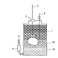
図1は第1の発明の実施形態の一例を示す図である。容器1に充填された有機塩素含有溶液10の中に吸着材20を投入し、溶液10と吸着材20とを長時間接触させることにより有機塩素化合物を吸着材20に吸着させる様子を模式的に示している。2は容器1の深さに合わせて吸着材20の位置を調整できるようにするための目盛付き支持棒で、3はシール材(例えば、ゴム栓)である。
(Embodiment 1)
FIG. 1 is a diagram showing an example of an embodiment of the first invention. A state in which the adsorbent 20 is put into the organic chlorine-containing
容器1には、溶液10中の有機塩素化合物濃度を測定するためのサンプリング口5、6が設けてある。サンプリング口5は、容器1底部の溶液の中に含まれる有機塩素化合物濃度を測定するためのものであり、サンプリング口5には、サンプリング管(サンプル抽出用シリンジ)4が連結されている。サンプリング口6は、容器1中間部の溶液の中に含まれる有機塩素化合物濃度を測定するためのものである。なお、サンプリング口は必要に応じて必要な位置に設ければよく、図1はその一例を示すものにすぎない。
The
容器1には、さらに温度計、攪拌手段(攪拌装置、循環ポンプ等)、加熱手段(リボンヒーター等)を、必要に応じて適宜設けることもできる。吸着材による吸着効率を高めるためには、攪拌手段や加熱手段を設けることが望ましい。
The
粉末、ペレットあるいはビーズ状の吸着材を使用する場合は、吸着材をそのまま溶液中へ投入することもできるが、かかる方法では回収操作が煩雑になる。回収操作を容易にする点より、吸着材を多孔質材料からなる容器に入れ、容器ごと溶液中に投入することが望ましい。多孔質材料としては、吸着材が該多孔質材料を介して溶液と接触できるものであればよく、例えば紙、織物、編物、樹脂フィルム等が挙げられる。容器としてガラスカラム等を用いることもできる。 When a powder, pellet or bead-shaped adsorbent is used, the adsorbent can be put into the solution as it is, but this method complicates the recovery operation. From the viewpoint of facilitating the recovery operation, it is desirable to place the adsorbent in a container made of a porous material and put the entire container into the solution. The porous material may be any material as long as the adsorbent can come into contact with the solution via the porous material, and examples thereof include paper, woven fabric, knitted fabric, and resin film. A glass column or the like can also be used as the container.
ハニカム型、格子状型、スパイラル型等の成形された吸着材を使用する場合は、支持棒2に吸着材20を固定して溶液10の中へ投入する。成形体の形状は、容器の形状に合わせて加工したものを使用すればよく、例えば、板状、紐状、シート状など適宜な形状であって構わない。
When using a molded adsorbent such as a honeycomb type, a lattice type, or a spiral type, the adsorbent 20 is fixed to the
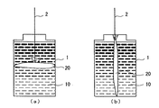
図2および図3には、吸着材の投入位置、投入形態の一例を示した。図2(a)は、多孔質材料製容器に入れた吸着材20を、容器1に充填された有機塩素化合物含有溶液10の中間部に投入した様子を模式的に示したものである。同様に、図2(b)は容器1の底部に投入した様子を模式的に示したものである。また、図3(a)は、容器の幅に合わせて調製した多孔質材料製容器に入れた吸着材20を、図3(b)は容器の高さに合わせて調製した多孔質材料製容器に入れた吸着材20を、それぞれ容器1に充填された有機塩素化合物含有溶液10に投入した様子を模式的に示したものである。
2 and 3 show an example of the adsorbent charging position and charging mode. FIG. 2A schematically shows a state in which the adsorbent 20 placed in a porous material container is introduced into an intermediate portion of the organochlorine compound-containing
なお、図2および図3は吸着材投入方法の一例を示したものであり、吸着材の投入位置や投入形状などは、容器の形状や有機塩素化合物の濃度に応じて選択することができる。経時で変えることもできる。 2 and 3 show an example of the adsorbent charging method, and the adsorbent charging position and charging shape can be selected according to the shape of the container and the concentration of the organic chlorine compound. It can also change over time.
(実施の形態2)
図4は第2の発明の実施形態の一例を示す図である。容器1に充填された有機塩素含有溶液10をポンプで循環し、容器1外に設置された吸着装置7(吸着材20が充填されている)を通過させ、溶液10と吸着材20とを接触させることにより有機塩素化合物を吸着材20に吸着させる様子を模式的に示している。3はシール材(例えば、ゴム栓)である。
(Embodiment 2)
FIG. 4 is a diagram showing an example of an embodiment of the second invention. The organic chlorine-containing
容器1には、溶液10中の有機塩素化合物濃度を測定するためのサンプリング口6が設けてある。サンプリング口6は、容器1中間部の溶液に含まれる有機塩素化合物濃度を測定するためのものであるが、サンプリング口は必要に応じて必要な位置に設ければよく、図4はその一例を示すものにすぎない。
The
容器1には、さらに温度計、攪拌手段(攪拌装置等)、加熱手段(リボンヒーター等)を、必要に応じて設けることもできる。吸着材による吸着効率を高めるためには、攪拌手段や加熱手段を設けることが望ましい。
The
本方法において、有機塩素化合物を含む溶液10と吸着材20との接触方法に特に制限はなく、例えば粒状、ビーズ状、ペレット状、あるいはハニカム型の成形体などを、回転式吸着塔あるいは固定式吸着塔等の従来公知の吸着装置に充填あるいは装着した吸着装置7に、循環溶液10を導入して通過させることにより、接触させることができる。
In this method, there is no particular limitation on the contact method between the
(実施の形態3)
図5は第2の発明の実施形態の別の一例を示す図であり、円筒状のポールトランス30に充填された絶縁油中の微量PCBの除去方法を説明する一部破断正面図である。外箱本体31と上蓋32とよりなるポールトランス部材には、コイル等33の隙間に微量PCBを含有する絶縁油35が充填されている。絶縁油の液面上部には隙間34があるので、上蓋32に取り付けた循環ポンプ8によって絶縁油35を循環させながら、上蓋32に取り付けた吸着装置7(粒状吸着材36が充填されている)を通過させ、絶縁油35と吸着材36とを接触させることによりPCBを吸着材36に吸着させる。図中の矢印は絶縁油の循環方向を示している。図5はポンプおよび吸着装置を隙間34に設置した例であるが、ポンプ、吸着装置は油中に設置してもよい。
(Embodiment 3)
FIG. 5 is a diagram showing another example of the embodiment of the second invention, and is a partially broken front view illustrating a method for removing a trace amount of PCB in the insulating oil filled in the
(実施の形態4)
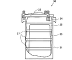
図6および図7は第1の発明の実施形態の別の一例を示す図であり、円筒状のポールトランス30に充填された絶縁油中の微量PCBの除去方法を説明する一部破断正面図である。外箱本体31と上蓋32とよりなるポールトランス部材には、コイル等33の隙間に微量PCBを含有する絶縁油35が充填されている。図6および図7では循環ポンプは図示していないが、図5と同様上蓋32など、ポールトランス内外に取り付けることもできる。
(Embodiment 4)
FIGS. 6 and 7 are views showing another example of the embodiment of the first invention, and are partially broken front views illustrating a method for removing a trace amount of PCB in the insulating oil filled in the
図6の例では、外箱本体31の形状(円筒状)に合わせて、リボン状の吸着材シート37を円筒状にして投入し、絶縁油35と吸着材シート37とを接触させることにより、絶縁油中のPCBを吸着材に吸着させる。この方法によれば、絶縁油に縦の流れが発生したときに効率よくPCBを吸着させることができる。
In the example of FIG. 6, in accordance with the shape (cylindrical) of the
図7の例では、外箱本体31の形状(円筒状)に合わせて、リボン状の吸着材シート37を縦棒状にして投入し、絶縁油35と吸着材シート37とを接触させることにより、絶縁油中のPCBを吸着材に吸着させる。この方法によれば、絶縁油に層流(横の流れ)が発生したときに効率よくPCBを吸着させることができる。
In the example of FIG. 7, in accordance with the shape (cylindrical shape) of the
図6および図7は、吸着材投入方法の一例を示したものであり、吸着材シートの投入位置や形状、大きさ、投入数などは、容器の形状やPCBの濃度に応じて選択することができ、経時で変えることもできる。また、図6と図7の形状のシートを併用することもできる。 6 and 7 show an example of the adsorbent charging method. The adsorbent sheet charging position, shape, size, number of charging, etc., should be selected according to the container shape and PCB concentration. Can be changed over time. Also, the sheets having the shapes shown in FIGS. 6 and 7 can be used in combination.
以上説明したように、本発明の方法で有機塩素化合物を吸着した吸着材は、有機塩素化合物とともに回収された後、PCB処理設備に輸送される。有機塩素化合物を吸着した吸着材の処理方法は特に限定されるものではないが、例えば、アルコール類等の溶離剤により処理する。これにより、吸着物質は溶離され、吸着材は再生される。一方、溶離液中の有機塩素化合物は、高濃度に濃縮され、回収される。脱着された有機塩素化合物は、高濃度溶液として回収することができるので後処理が容易である。後処理方法としては化学的分解方法等があり、その方法は特に限定されるものではないが、例えば、水熱処理、酸化分解、還元分解、紫外線照射やマイクロ波による光分解等を挙げることができる。 As described above, the adsorbent adsorbed with the organic chlorine compound by the method of the present invention is recovered together with the organic chlorine compound and then transported to the PCB processing facility. Although the processing method of the adsorbent which adsorb | sucked the organic chlorine compound is not specifically limited, For example, it processes with eluents, such as alcohol. As a result, the adsorbed material is eluted and the adsorbent is regenerated. On the other hand, the organochlorine compound in the eluent is concentrated to a high concentration and recovered. Since the desorbed organochlorine compound can be recovered as a high-concentration solution, post-treatment is easy. The post-treatment method includes a chemical decomposition method and the like, and the method is not particularly limited. Examples thereof include hydrothermal treatment, oxidative decomposition, reductive decomposition, ultraviolet light irradiation and microwave photolysis. .
有機塩素化合物が除去された絶縁油等の油は、「廃棄物の処理及び清掃に関する法律」に定められている処理基準値(0.5ppm以下)を満足するものとなり、トランス、コンデンサ等の絶縁油として再利用することができる。 Oil such as insulating oil from which organochlorine compounds have been removed will satisfy the treatment standard value (0.5 ppm or less) stipulated in the “Law on Waste Disposal and Cleaning” and insulation of transformers, capacitors, etc. Can be reused as oil.
以下、実施例及び比較例を用いて本発明を更に具体的に説明するが、本発明は以下の実施例のみに限定されるものではない。 Hereinafter, the present invention will be described more specifically with reference to Examples and Comparative Examples, but the present invention is not limited to only the following Examples.
(実施例1)
ポールトランス部材のモデルとして三角フラスコを用いて吸着試験を行った。2ppmPCB含有溶液を用意し、溶媒は絶縁油7種4号(鉱油、アルキルベンゼン)および絶縁油2種(1〜4号混合、アルキルベンゼン)の2種類を用いた。2ppmPCB溶液各100mlを200mlの三角フラスコに入れ、5gの活性炭(三菱化学「ダイヤホープ008」、原料:石炭、形状:粉砕状)を加え、40℃加温、超音波(8時間/日)(ヤマト BRANSON−8210型、超音波出力200W)、振とう機にて100rpmで水平方向へ振とうさせ、下記の表1の各時間毎に、PCBの液中濃度を分析し、活性炭への吸着度合いを測定した。実験は2種類の絶縁油とも3点実施した。経時によるPCBの液中濃度を表1に、また吸着時間とPCB濃度(各3回の平均値)との関係を図8に示す。
(Example 1)
An adsorption test was performed using an Erlenmeyer flask as a model of the pole transformer member. A 2 ppm PCB-containing solution was prepared, and two kinds of solvents, insulating

表1の結果から、吸着時間を長くする程溶液中のPCB濃度が低下することがわかる。また図8の結果から、吸着時間約100時間でPCB濃度が0.5ppm以下になることがわかる。 From the results in Table 1, it can be seen that the longer the adsorption time, the lower the PCB concentration in the solution. Moreover, it can be seen from the results of FIG. 8 that the PCB concentration becomes 0.5 ppm or less after the adsorption time of about 100 hours.
1 容器
2 支持棒
3 シール材
4 サンプリング管
5,6 サンプリング口
7 吸着装置
8 ポンプ
10 溶液
20 吸着材
30 ポールトランス
31 ポールトランス外箱本体
32 ポールトランス上蓋
33 コイル等
34 上部隙間
35 絶縁油
36 粒状吸着材
37 シート状吸着材
DESCRIPTION OF
30
Claims (6)
Priority Applications (1)
| Application Number | Priority Date | Filing Date | Title |
|---|---|---|---|
| JP2003434792A JP2005111470A (en) | 2003-09-18 | 2003-12-26 | Method for removing chlorinated organic compound |
Applications Claiming Priority (2)
| Application Number | Priority Date | Filing Date | Title |
|---|---|---|---|
| JP2003325753 | 2003-09-18 | ||
| JP2003434792A JP2005111470A (en) | 2003-09-18 | 2003-12-26 | Method for removing chlorinated organic compound |
Publications (1)
| Publication Number | Publication Date |
|---|---|
| JP2005111470A true JP2005111470A (en) | 2005-04-28 |
Family
ID=34554556
Family Applications (1)
| Application Number | Title | Priority Date | Filing Date |
|---|---|---|---|
| JP2003434792A Pending JP2005111470A (en) | 2003-09-18 | 2003-12-26 | Method for removing chlorinated organic compound |
Country Status (1)
| Country | Link |
|---|---|
| JP (1) | JP2005111470A (en) |
Cited By (2)
| Publication number | Priority date | Publication date | Assignee | Title |
|---|---|---|---|---|
| JP2007069055A (en) * | 2005-09-02 | 2007-03-22 | Tokyo Electric Power Co Inc:The | Separation method for organic chlorine compound combined with adsorbent material |
| JP2020025905A (en) * | 2018-08-09 | 2020-02-20 | 株式会社大丸テクノ | Waste liquid treatment method and waste liquid treatment device |
Citations (7)
| Publication number | Priority date | Publication date | Assignee | Title |
|---|---|---|---|---|
| JPS609503U (en) * | 1983-06-27 | 1985-01-23 | 古家後 隆補 | Water in oil adsorber |
| JPS6127932A (en) * | 1984-06-04 | 1986-02-07 | ロツクウエル インタ−ナシヨナル コ−ポレ−シヨン | Removal of polyhalogenated biphenyl from organic liquid |
| JPH01107581U (en) * | 1988-01-13 | 1989-07-20 | ||
| JP2000323342A (en) * | 1999-05-14 | 2000-11-24 | Daihen Corp | Method and device for disassembling wound iron core |
| JP2002233859A (en) * | 2001-02-08 | 2002-08-20 | Konoike Constr Ltd | Method for decontaminating contaminated soil containing oleaginous harmful substance or the like and facility and system therefor |
| JP2002367431A (en) * | 2001-06-05 | 2002-12-20 | Nippon Oil Corp | Insulating oil composition |
| JP2003225507A (en) * | 2002-02-05 | 2003-08-12 | Toshiba Corp | Treatment method for oils and fats |
-
2003
- 2003-12-26 JP JP2003434792A patent/JP2005111470A/en active Pending
Patent Citations (7)
| Publication number | Priority date | Publication date | Assignee | Title |
|---|---|---|---|---|
| JPS609503U (en) * | 1983-06-27 | 1985-01-23 | 古家後 隆補 | Water in oil adsorber |
| JPS6127932A (en) * | 1984-06-04 | 1986-02-07 | ロツクウエル インタ−ナシヨナル コ−ポレ−シヨン | Removal of polyhalogenated biphenyl from organic liquid |
| JPH01107581U (en) * | 1988-01-13 | 1989-07-20 | ||
| JP2000323342A (en) * | 1999-05-14 | 2000-11-24 | Daihen Corp | Method and device for disassembling wound iron core |
| JP2002233859A (en) * | 2001-02-08 | 2002-08-20 | Konoike Constr Ltd | Method for decontaminating contaminated soil containing oleaginous harmful substance or the like and facility and system therefor |
| JP2002367431A (en) * | 2001-06-05 | 2002-12-20 | Nippon Oil Corp | Insulating oil composition |
| JP2003225507A (en) * | 2002-02-05 | 2003-08-12 | Toshiba Corp | Treatment method for oils and fats |
Cited By (2)
| Publication number | Priority date | Publication date | Assignee | Title |
|---|---|---|---|---|
| JP2007069055A (en) * | 2005-09-02 | 2007-03-22 | Tokyo Electric Power Co Inc:The | Separation method for organic chlorine compound combined with adsorbent material |
| JP2020025905A (en) * | 2018-08-09 | 2020-02-20 | 株式会社大丸テクノ | Waste liquid treatment method and waste liquid treatment device |
Similar Documents
| Publication | Publication Date | Title |
|---|---|---|
| Zhu et al. | Simultaneous sorption of organic compounds and phosphate to inorganic–organic bentonites from water | |
| Zolfaghari et al. | Taguchi optimization approach for Pb (II) and Hg (II) removal from aqueous solutions using modified mesoporous carbon | |
| Manohar et al. | Adsorption performance of Al-pillared bentonite clay for the removal of cobalt (II) from aqueous phase | |
| Vinod et al. | Sorption of tannic acid on zirconium pillared clay | |
| Szala et al. | BTX sorption on Na-P1 organo-zeolite as a process controlled by the amount of adsorbed HDTMA | |
| Torabian et al. | Removal of petroleum aromatic hydrocarbons by surfactant‐modified natural zeolite: the effect of surfactant | |
| Erto et al. | A procedure to design a Permeable Adsorptive Barrier (PAB) for contaminated groundwater remediation | |
| WO2007056717A2 (en) | Methods and devices for the removal of organic contaminants from water | |
| WO2010073818A1 (en) | Purifying agent for oily liquid containing polybiphenyl chloride | |
| Hu et al. | Microwave-induced degradation of N-nitrosodimethylamine (NDMA) sorbed in zeolites: Effect of mineral surface chemistry and non-thermal effect of microwave | |
| Bentaleb et al. | Enhanced adsorption of 2, 4-dichlorophenol from aqueous solution using modified low cost Algerian geomaterial | |
| Muir et al. | The removal of organic compounds by natural and synthetic surface-functionalized zeolites: A mini-review | |
| Reyes et al. | Application of illite-and kaolinite-rich clays in the synthesis of zeolites for wastewater treatment | |
| KR101680610B1 (en) | Activated carbon adsorbent for acidic gas removal and manufacturing method the same | |
| Nurliati et al. | Studies of modification of zeolite by tandem acid-base treatments and its adsorptions performance towards thorium | |
| Chen et al. | Facile synthesis of calcite-impregnated hydrochar with high sorption capacity for Cu (II) from aqueous solution | |
| JP2005111470A (en) | Method for removing chlorinated organic compound | |
| Gokulakrishnan et al. | Uptake of decontaminating agent from aqueous solution: a study on adsorption behaviour of oxalic acid over Al-MCM-41 adsorbents | |
| Andrunik et al. | Functionalized adsorbents resulting from the transformation of fly ash: characterization, modification, and adsorption of pesticides | |
| Abatal et al. | Comparative adsorption behavior between phenol and p-nitrophenol by Na-and HDTMA-clinoptilolite-rich tuff | |
| Sekrane et al. | Adsorption of toluene on bentonites modified by dodecyltrimethylammonium bromide | |
| Huang et al. | Sorption of 2, 4-dichlorophenol onto organobentonites: influence of organic cation structure and bentonite layer charge | |
| Capasso et al. | Removal of humic substances from water by means of calcium‐ion‐enriched natural zeolites | |
| KR100779528B1 (en) | A practical method and apparatus for disposing pcbs in oil | |
| Abatal et al. | Evaluating of effectiveness of a natural and modified surface mexican clinoptilolite-rich tuff in removing phenol and p-nitrophenol from aqueous solutions |
Legal Events
| Date | Code | Title | Description |
|---|---|---|---|
| A621 | Written request for application examination |
Effective date: 20061117 Free format text: JAPANESE INTERMEDIATE CODE: A621 |
|
| A131 | Notification of reasons for refusal |
Free format text: JAPANESE INTERMEDIATE CODE: A131 Effective date: 20091124 |
|
| A521 | Written amendment |
Effective date: 20100121 Free format text: JAPANESE INTERMEDIATE CODE: A523 |
|
| A131 | Notification of reasons for refusal |
Effective date: 20100823 Free format text: JAPANESE INTERMEDIATE CODE: A131 |
|
| A521 | Written amendment |
Effective date: 20101007 Free format text: JAPANESE INTERMEDIATE CODE: A523 |
|
| A02 | Decision of refusal |
Free format text: JAPANESE INTERMEDIATE CODE: A02 Effective date: 20110510 |