JP2005106949A - Camera system - Google Patents
Camera system Download PDFInfo
- Publication number
- JP2005106949A JP2005106949A JP2003337566A JP2003337566A JP2005106949A JP 2005106949 A JP2005106949 A JP 2005106949A JP 2003337566 A JP2003337566 A JP 2003337566A JP 2003337566 A JP2003337566 A JP 2003337566A JP 2005106949 A JP2005106949 A JP 2005106949A
- Authority
- JP
- Japan
- Prior art keywords
- focus
- camera
- lens
- autofocus
- drive signal
- Prior art date
- Legal status (The legal status is an assumption and is not a legal conclusion. Google has not performed a legal analysis and makes no representation as to the accuracy of the status listed.)
- Granted
Links
Images
Landscapes
- Studio Devices (AREA)
- Focusing (AREA)
- Lens Barrels (AREA)
- Automatic Focus Adjustment (AREA)
Abstract
【課題】オートフォーカスモード時にフォーカス操作部の操作量に応じた制御をすることができ、また、フォーカスレンズ群の駆動量との関係などをカメラ側で設定・変更することが可能となるカメラシステムを提供する。
【解決手段】カメラ側でオートフォーカス制御する一方、レンズ側でマニュアルフォーカス制御するカメラシステムにおいて、前記カメラ側のオートフォーカス制御信号生成手段は、オートフォーカスモード時にマニュアル操作した際に、レンズ側の変位信号出力手段から出力されるマニュアルフォーカス操作部の操作量に応じた変位信号を用いてオートフォーカス駆動信号を演算する構成を備え、上記オートフォーカスモード時には常に前記カメラ側のオートフォーカス制御信号生成手段からの駆動信号によりフォーカスレンズを駆動制御できるように構成する。
【選択図】 図1A camera system capable of performing control according to an operation amount of a focus operation unit in an autofocus mode and setting / changing a relationship with a driving amount of a focus lens group on a camera side. I will provide a.
In a camera system in which auto focus control is performed on the camera side and manual focus control is performed on the lens side, the auto focus control signal generation unit on the camera side is displaced on the lens side when manually operated in the auto focus mode. It has a configuration for calculating an autofocus drive signal using a displacement signal corresponding to the operation amount of the manual focus operation unit output from the signal output means, and always from the autofocus control signal generation means on the camera side in the autofocus mode. The focus lens can be driven and controlled by this driving signal.
[Selection] Figure 1
Description
本発明は、カメラシステムに関し、特にレンズ交換可能なビデオカメラやテレビカメラ等のカメラシステムに関するものである。 The present invention relates to a camera system, and more particularly to a camera system such as a video camera or a television camera with interchangeable lenses.
従来の交換式レンズを含むカメラシステムにおいて、オートフォーカス機能を備え、マニュアルフォーカスも可能としたカメラシステムが知られている。これらのカメラシステムでは、例えば特許文献1に示されているように、オートフォーカス機能を実現するためにリアフォーカス駆動方式が一般的に用いられており、また、そこでマニュアルフォーカス操作をする際は、電子リングと呼ばれるフォーカス操作部を操作してフォーカス操作を行うような方式が一般的に採られている。
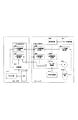
このような従来のカメラシステムを、図4から図7に示す。
図4は、このような従来のカメラシステムの構成を示す図である。また、図5はこのようなカメラシステムにおけるフォーカスレンズ群の制御を行うレンズCPUの動作を説明するフローチャートであり、図6はオートフォーカス用の駆動信号の演算を行うカメラ側CPUの動作を説明するフローチャートである。
In a conventional camera system including an interchangeable lens, a camera system having an autofocus function and capable of manual focus is known. In these camera systems, for example, as shown in Patent Document 1, a rear focus drive system is generally used to realize an autofocus function, and when performing manual focus operation there, A method of performing a focus operation by operating a focus operation unit called an electronic ring is generally adopted.
Such a conventional camera system is shown in FIGS.
FIG. 4 is a diagram showing the configuration of such a conventional camera system. FIG. 5 is a flowchart for explaining the operation of the lens CPU for controlling the focus lens group in such a camera system, and FIG. 6 for explaining the operation of the camera side CPU for calculating the autofocus drive signal. It is a flowchart.
つぎに、これらの図により、従来のカメラシステムにおけるオートフォーカスモード時の動作を簡単に説明する。
図6において、オートフォーカスモードの場合、ステップ603においてカメラ側CPU419はCCD413から出力される映像信号に基づいてAF処理部414が生成したAF評価値を入力し、ステップ604で該AF評価値を用いてAF処理状態に応じてオートフォーカス用駆動信号を演算し、ステップ605でレンズ401に出力する。
このときカメラ側CPU419は、いわゆる山登り方式を用いてAF評価値が最大となるようにオートフォーカス駆動信号を演算し、フォーカスレンズ群403を駆動制御している。この山登り方式のオートフォーカス動作を説明するフローチャートを図7に示す。
Next, referring to these drawings, the operation in the autofocus mode in the conventional camera system will be briefly described.
In FIG. 6, in the auto focus mode, the camera side CPU 419 inputs the AF evaluation value generated by the
At this time, the camera-side CPU 419 calculates an autofocus drive signal so as to maximize the AF evaluation value using a so-called hill-climbing method, and drives and controls the
このような山登り方式は、例えば、特許文献2に記載されているように、映像信号の中から、水平同期信号及び、垂直同期信号を検出し、映像信号処理のための基準信号を生成し、そして基準信号より、被写体の鮮鋭度評価値に応じた信号を抽出して評価し、その信号が大きくなる方向へフォーカスレンズを移動させ、最大となるところで停止させる方式であるが、この方式はオートフォーカス制御を行う際に一般的に用いられている方式であるので、これ以上の詳細な説明は省略する。 Such a hill-climbing method, for example, as described in Patent Document 2, detects a horizontal synchronization signal and a vertical synchronization signal from a video signal, generates a reference signal for video signal processing, Then, a signal corresponding to the sharpness evaluation value of the subject is extracted from the reference signal and evaluated, and the focus lens is moved in the direction in which the signal increases and stopped at the maximum. Since this method is generally used when focus control is performed, further detailed description is omitted.
つぎに、 このような山登り方式等を用いた上記した従来のカメラシステムにおけるオートフォーカス時の動作を説明する。
オートフォーカスモードにおいて、フォーカス操作部404が操作されず変位検出部405からの出力変位がない限り、図5に示されるようにステップ509においてレンズ側CPU418はカメラ402側のオートフォーカス用駆動信号出力部415から出力されるオートフォーカス用駆動信号をオートフォーカス用駆動信号入力部409に入力する一方、ステップ510でレンズ位置検出部407からレンズ位置信号を入力し、ステップ511でこれらのオートフォーカス用駆動信号とレンズ位置信号とを用いて、フォーカス制御演算を行ってモータを駆動し、被写体に合焦するようにフォーカスレンズ群403を制御する。
Next, an operation at the time of autofocus in the above-described conventional camera system using such a mountain climbing method will be described.
In the auto-focus mode, as long as the
これに対して、このようなオートフォーカスモード時に、フォーカス操作部404が操作されると、図5に示されるようにステップ508においてステップ503からステップ506の作動に移行する。すなわち、レンズCPU418は、カメラ402から入力されるオートフォーカス用駆動信号の使用を中止し、ステップ503において変位検出部405の出力からマニュアルフォーカス用駆動信号を演算し、このマニュアルフォーカ用駆動信号をフォーカス駆動信号とする。そして、ステップ504でフォーカス変位信号をカメラに出力する一方、ステップ505でフィードバック信号に相当するレンズ位置検出部407の出力であるレンズ位置信号を入力し、ステップ506でこれらのフォーカス駆動信号と位置信号を用いてフォーカス制御演算を行ってモータを駆動し、フォーカスレンズ群403を制御する。この後レンズCPU418は、オートフォーカスモードからマニュアルフォーカスモードに移行したことをカメラCPU419に送信し、カメラCPU419のオートフォーカス処理を一旦終了させる。カメラCPU419はこれを受け、オートフォーカス動作を再起動待ちに設定変更し、レンズから再度オートフォーカスモードへの移行を示すデータが送信されることを待つ(図6のステップ606参照)。
以上に説明したように、従来のカメラシステムにおいては、レンズCPU419はフォーカス操作部が操作されることにより、オートフォーカスモードからマニュアルフォーカスモードに自動的に移行する方式が採られていた。
As described above, in the conventional camera system, the lens CPU 419 automatically shifts from the autofocus mode to the manual focus mode when the focus operation unit is operated.
しかしながらオートフォーカス動作は、その性質上必ずしも撮影者の意図した被写体に合焦するとは限らない。そのためオートフォーカス動作中に撮影者がフォーカス操作部を操作して、別の合焦点にフォーカスレンズを駆動し、オートフォーカス動作を再起動させることがある。そのような場合、上記従来例では、オートフォーカスモード時にフォーカス操作部が操作されても、レンズ側だけでフォーカス制御が完結し、フォーカス操作部の操作量と、フォーカスレンズ群の駆動量との関係などをカメラ側で設定・変更することができなかった。 However, the autofocus operation does not always focus on the subject intended by the photographer due to its nature. Therefore, the photographer may operate the focus operation unit during the autofocus operation to drive the focus lens to another in-focus point and restart the autofocus operation. In such a case, in the above conventional example, even when the focus operation unit is operated in the autofocus mode, the focus control is completed only on the lens side, and the relationship between the operation amount of the focus operation unit and the drive amount of the focus lens group Etc. could not be set or changed on the camera side.
そこで、本発明は、上記課題を解決し、オートフォーカスモード時に撮影者がフォーカス操作部を操作した際においても、フォーカス操作部の操作量に応じた制御をすることができ、また、フォーカスレンズ群の駆動量との関係などをカメラ側で設定・変更することが可能となり、フォーカス操作性を向上させることができるカメラシステムを提供することを目的とするものである。 Therefore, the present invention solves the above-described problem, and can perform control according to the operation amount of the focus operation unit even when the photographer operates the focus operation unit in the autofocus mode, and the focus lens group It is an object of the present invention to provide a camera system capable of setting / changing the relationship with the driving amount on the camera side and improving the focus operability.
本発明は、以下のように構成したカメラシステムを提供するものである。
すなわち、本発明のカメラシステムは、カメラ側のオートフォーカス制御信号生成手段によって生成された信号をレンズ側に出力してフォーカスレンズをオートフォーカス制御する一方、レンズ側のマニュアルフォーカス操作部の操作によりマニュアルフォーカス駆動信号生成手段から出力された信号によってフォーカスレンズをマニュアルフォーカス制御するカメラシステムにおいて、
前記カメラ側のオートフォーカス制御信号生成手段は、前記マニュアルフォーカス操作部をオートフォーカスモード時に操作した際に、レンズ側の変位信号出力手段から出力される前記マニュアルフォーカス操作部の操作量に応じた変位信号を用いてオートフォーカス駆動信号を演算する構成を備え、上記オートフォーカスモード時には常に前記カメラ側のオートフォーカス制御信号生成手段からの駆動信号によりフォーカスレンズを駆動制御することを特徴としている。
また、本発明のカメラシステムは、前記変位信号出力手段を、前記マニュアルフォーカス操作部の操作量を検出して、前記マニュアルフォーカス駆動信号生成手段に出力する変位検出部からの出力を、オートフォーカスモード時において前記カメラ側に出力するように構成することができる。
また、本発明のカメラシステムは、前記カメラ側で設定した任意係数を用いて、前記マニュアルフォーカス操作部の操作量と、該操作量に基づいて前記マニュアルフォーカス駆動信号生成手段により生成される駆動信号との関係を、前記カメラ側で設定・変更可能に構成することができる。
また、本発明のカメラシステムは、前記カメラ側に対して、前記レンズ側を交換可能とした構成を採ることができる。
The present invention provides a camera system configured as follows.
That is, the camera system of the present invention outputs the signal generated by the camera-side autofocus control signal generation means to the lens side to perform autofocus control of the focus lens, while manually operating the lens side manual focus operation unit. In the camera system for manually focusing the focus lens by the signal output from the focus drive signal generation means,
The camera-side autofocus control signal generating means is a displacement according to an operation amount of the manual focus operation section output from the lens-side displacement signal output means when the manual focus operation section is operated in the autofocus mode. A configuration is provided in which an autofocus drive signal is calculated using a signal, and the focus lens is driven and controlled by a drive signal from the camera-side autofocus control signal generation means at all times in the autofocus mode.
In the camera system of the present invention, the displacement signal output means detects the operation amount of the manual focus operation section, and outputs the displacement detection section output to the manual focus drive signal generation means with an autofocus mode. It can be configured to output to the camera side at the time.
Further, the camera system of the present invention uses an arbitrary coefficient set on the camera side, an operation amount of the manual focus operation unit, and a drive signal generated by the manual focus drive signal generation unit based on the operation amount Can be set and changed on the camera side.
In addition, the camera system of the present invention can adopt a configuration in which the lens side can be exchanged with respect to the camera side.
本発明によれば、オートフォーカスモード時に撮影者がフォーカス操作部を操作した際においても、フォーカス操作部の操作量に応じた制御をすることができ、また、フォーカスレンズ群の駆動量との関係などをカメラ側で設定・変更することが可能となり、フォーカス操作性を向上させることができるカメラシステムを実現することができる。 According to the present invention, even when the photographer operates the focus operation unit in the autofocus mode, the control according to the operation amount of the focus operation unit can be performed, and the relationship with the drive amount of the focus lens group And the like can be set and changed on the camera side, and a camera system capable of improving the focus operability can be realized.
本発明を実施するための最良の形態を、以下の実施例により説明する。 The best mode for carrying out the present invention will be described by the following examples.
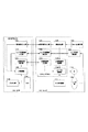
図1に、本発明の実施例におけるカメラシステムの構成を示す。
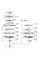
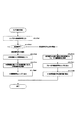
また、図2にこのようなカメラシステムにおけるフォーカスレンズ群の制御を行うレンズCPUの動作を説明するフローチャートを示し、図3にはオートフォーカス用の駆動信号の演算を行うカメラ側CPUの動作を説明するフローチャートを示す。
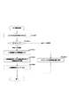
まず、図1により本実施例のカメラシステムの構成について説明する。
図1において、101は交換式のレンズ、102は交換式のレンズを着脱可能なカメラ、103は焦点調節用のフォーカスレンズ群、104はフォーカスレンズ群3を制御するためのフォーカス操作部である。また、105はフォーカス操作部104の操作量を検出するための変位検出部、106は変位検出部105の出力からマニュアルフォーカス制御信号を生成するMF駆動信号生成部である。
107は変位検出部105の出力をカメラ102に出力するための変位信号出力部、108はフォーカスレンズ群103の位置を検出するための位置検出部、109は位置検出部108の出力に基づいてフォーカスレンズ群103の位置情報をカメラ102に出力するためのレンズ位置情報出力部である。
FIG. 1 shows the configuration of a camera system in an embodiment of the present invention.
FIG. 2 shows a flowchart for explaining the operation of the lens CPU for controlling the focus lens group in such a camera system, and FIG. 3 shows the operation of the camera side CPU for calculating the autofocus drive signal. The flowchart to perform is shown.
First, the configuration of the camera system of this embodiment will be described with reference to FIG.
In FIG. 1, 101 is an interchangeable lens, 102 is a camera to which an interchangeable lens can be attached, 103 is a focus lens group for focus adjustment, and 104 is a focus operation unit for controlling the focus lens group 3. Reference numeral 105 denotes a displacement detection unit for detecting the operation amount of the
107 is a displacement signal output unit for outputting the output of the displacement detection unit 105 to the
110はカメラ102からのオートフォーカス用駆動信号を入力するためのAF駆動信号入力部、111はオートフォーカスモードとマニュアルフォーカスモードを切換えるためのAF/MF切換手段である。また、112はマニュアルフォーカス制御信号およびフォーカスレンズ群103の位置情報、オートフォーカス用駆動信号、AF/MF切換手段の状態に基づいてフォーカスレンズ群103の制御演算を行い、モータ113を駆動するためのモータ駆動信号を演算するフォーカス制御部である。
113はフォーカスレンズ群103を駆動するためのモータ、114はフォーカスレンズ群103および不図示の光学系を介して結像された像を光電変換するCCDであり、115はCCD114の出力である映像信号に基づいてオートフォーカス演算を行い、合焦するにしたがってその値が大きくなるAF評価値を生成するAF処理部である。
116はAF評価値が増加するようにフォーカスレンズ群103を駆動するための駆動信号を生成し、レンズ101に出力するためのAF用駆動信号出力部であり、117はフォーカスレンズ群103の位置情報を入力するためのレンズ位置情報入力部、118はレンズ1からフォーカス操作部104の操作量に応じた変位信号を入力する変位信号入力部、119はCCD114の出力である映像信号を標準テレビ信号に変換するためのプロセス部である。
Reference numeral 116 denotes an AF drive signal output unit for generating a drive signal for driving the
本実施例では、レンズ101にCPU120を構成し、またカメラ102にCPU121を構成している。MF駆動信号生成部106および変位信号出力部107、レンズ位置情報出力部109、AF駆動信号入力部110、フォーカス制御部112がレンズCPU120に相当し、AF駆動信号出力部116、レンズ位置情報入力部117、変位信号入力部118がカメラCPU121に相当する。
In this embodiment, the lens 101 is configured with a CPU 120, and the
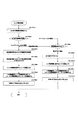
以下に、図2のフローチャートを用いて本実施例におけるレンズCPU120の動作を説明する。
レンズCPU120は、まずステップ201で現在のフォーカスモードがオートフォーカスかマニュアルフォーカスかを判断するために、AF/MF切換部111の状態を入力する。ステップ202で入力したAF/MF切換部の状態を判断し、マニュアルフォーカスモードの場合は、レンズ側だけでフォーカス制御を行うようにステップ203に進み、フォーカス操作部104の操作量に応じたフォーカス駆動信号を生成するために、変位検出部105の出力を用いてマニュアルフォーカス駆動信号を演算する。
The operation of the lens CPU 120 in this embodiment will be described below using the flowchart of FIG.
In step 201, the lens CPU 120 first inputs the state of the AF / MF switching unit 111 in order to determine whether the current focus mode is auto focus or manual focus. The state of the AF / MF switching unit input in step 202 is determined, and in the case of the manual focus mode, the process proceeds to step 203 so that focus control is performed only on the lens side, and focus driving according to the operation amount of the
ステップ204では、カメラ102でフォーカス操作部104の操作状態を把握できるようにするために、変位検出部105の出力信号をレンズ側の変位信号出力部107から、カメラ102側の変位信号入力部118に出力する。
ステップ205では、フォーカスレンズ制御演算時に必要なフォーカスレンズ群103の位置情報を把握するために、レンズ位置検出部108から位置情報をレンズ側のレンズ位置情報出力部109から出力し、この出力情報をカメラ102側のレンズ位置情報入力部117に入力する。
In step 204, in order that the
In step 205, in order to grasp the position information of the
ステップ206では、フォーカスの指令信号であるマニュアルフォーカス駆動信号と、フィードバック信号であるフォーカスレンズ群103の位置情報を用いてフォーカス制御演算を行う。そしてステップ207でフォーカス制御演算の結果をモータ113に出力し、フォーカスレンズ群103をフォーカス操作部104の操作量に応じてマニュアルフォーカス駆動する。ここまでが、フォーカス操作部の操作量に応じてフォーカスレンズ群103を駆動するマニュアルフォーカスモードにおける動作である。マニュアルフォーカスモードは、上記のようにレンズ側CPUのみで制御を行うモードである。
In step 206, a focus control calculation is performed using a manual focus drive signal that is a focus command signal and position information of the
他方、ステップ202において、AF/MF切換部がオートフォーカスモードの場合には、ステップ208にジャンプする。ステップ208ではカメラ102でフォーカス操作部104の操作状態を把握できるようにするために、変位検出部105の出力信号をカメラ102に出力する。ここで、フォーカス操作部104が操作されていない場合、ステップ209でカメラCPU121で演算したオートフォーカス駆動信号に応じてフォーカスレンズ群103を駆動するために、カメラ側のAF駆動信号出力部116からの出力信号を、レンズ側のAF駆動信号入力部110に入力する。
On the other hand, if the AF / MF switching unit is in the autofocus mode in step 202, the routine jumps to step 208. In step 208, the output signal of the displacement detection unit 105 is output to the
つづいて、ステップ210では、現在のフォーカスレンズ群103の位置を把握するために、レンズ位置検出部108からフォーカスレンズ群103の位置情報を入力する。そしてステップ211で、オートフォーカスモードにおけるフォーカスの指令信号であるオートフォーカス用駆動信号と、フィードバック信号に相当するフォーカスレンズ群103の位置情報を用いてフォーカス制御演算を行う。その演算結果をステップ212でモータ113に出力し、被写体に合焦するようにフォーカスレンズ群103をオートフォーカス駆動する。このようにオートフォーカスモード時は、CCD114から出力される映像信号に基づいてオートフォーカス駆動信号をカメラCPU121で演算し、レンズCPU120はそのオートフォーカス駆動信号に応じてフォーカスレンズ群103の制御を行う。
Subsequently, in step 210, position information of the
これに対して、オートフォーカスモード時、撮影者が意図した被写体に合焦させるため、フォーカス操作部104を操作した場合、本実施例のカメラシステムにおいては、カメラ102からのオートフォーカス用駆動信号を用いて、つぎのようにフォーカスレンズ群103の制御を行うように構成されている。すなわち、本実施例のカメラシステムにおいては、上記したようにAF/MF切換部がオートフォーカスモードの場合には、ステップ208において、カメラ102でフォーカス操作部104の操作状態を把握できるようにするために、変位検出部105の出力信号がカメラ102に出力さており、これによりフォーカス操作部104の操作量に応じた変位信号がレンズ101からカメラ102に送信され、カメラ102側でこの変位信号を用いて上記したステップ211でフォーカス駆動信号が演算される。そして、このカメラCPU121で演算したオートフォーカス駆動信号をカメラ側のAF駆動信号出力部116から出力し、レンズ側のAF駆動信号入力部110に入力して、このオートフォーカス駆動信号に応じてフォーカスレンズ群103を駆動する。
On the other hand, in the autofocus mode, when the
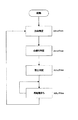
次に、図3のフローチャートを用いて、本実施例におけるカメラCPU121の動作を説明する。
カメラCPU121は、まずステップ301でフォーカス操作部が操作されたかどうかを把握するために、レンズ101からフォーカス操作部104の操作量に応じた変位信号を入力する。
ステップ302で入力した変位信号の値を判断し、変位信号が0の場合、つまりフォーカス操作部104が操作されていない場合は、オートフォーカス用駆動信号を生成するためにステップ303でAF処理部115から被写体への合焦度に対応したAF評価値を入力する。
ステップ304では、より被写体への合焦度をあげるために、入力したAF評価値を用いて、方向判定・山登り判定・頂上判定・再起動まちの各AF処理状態に応じたオートフォーカス用駆動信号を演算する。そして、ステップ305で、得られたオートフォーカス用駆動信号に応じてフォーカスレンズ群103を駆動するために、オートフォーカス用駆動信号をフォーカス制御部112のあるレンズ101に出力する。
Next, the operation of the camera CPU 121 in this embodiment will be described using the flowchart of FIG.
The camera CPU 121 first inputs a displacement signal corresponding to the operation amount of the
The value of the displacement signal input in step 302 is determined. If the displacement signal is 0, that is, if the
In step 304, in order to further increase the degree of focus on the subject, an autofocus drive signal corresponding to each AF processing state of direction determination, mountain climbing determination, peak determination, and restarting town using the input AF evaluation value. Is calculated. In step 305, in order to drive the
また、ステップ302において、レンズ101から入力した変位信号が0以外の場合、つまりフォーカス操作部104が操作されている場合は、マニュアルフォーカスモードに移行する。ステップ306にジャンプし、入力した変位信号とカメラ102側で任意に設定可能な1つ以上の係数を用いて、フォーカス操作部104の操作量に応じたマニュアルフォーカス用駆動信号を演算する。そしてステップ307でフォーカス駆動信号をレンズ101に出力し、ステップ308でオートフォーカス処理状態は再起動待ちに設定する。
In step 302, when the displacement signal input from the lens 101 is other than 0, that is, when the
このとき、AF/MF切換部111がオートフォーカスモードに設定されている場合は、レンズCPU120は、カメラ側のマニュアルフォーカス駆動信号に応じてフォーカスレンズ群103を駆動し、AF/MF切換部がマニュアルフォーカスモードの場合は、レンズ側のMF駆動信号生成部で生成されたマニュアルフォーカス駆動信号に応じてフォーカスレンズ群103を駆動する。
At this time, if the AF / MF switching unit 111 is set to the autofocus mode, the lens CPU 120 drives the
このように本実施例においては、レンズ101はオートフォーカスモードの場合は、常時カメラ102から送信されたフォーカス駆動信号に応じてフォーカスレンズ群103を制御するように構成され、このオートフォーカスモード時にフォーカス操作部104が操作された場合、フォーカス操作部104の操作量に応じた変位信号をレンズ101からカメラ102に送信し、カメラ102側でこの変位信号を用いてオートフォーカス駆動信号を演算し、このオートフォーカス駆動信号に応じて、フォーカスレンズ群103を駆動するように構成されている。したがって、これによれば、オートフォーカスモード時におけるフォーカス操作部104の操作量と、フォーカスレンズ群の駆動量との関係がカメラ側で設定・変更され、意図したフォーカス操作と、オートフォーカス性能の向上を図ることが可能となる
Thus, in this embodiment, when the lens 101 is in the autofocus mode, the
101:レンズ
102:カメラ
103:フォーカスレンズ群
104:フォーカス操作部
105:変位検出部
106:マニュアルフォーカス(MF)駆動信号生成部
107:変位信号出力部
108:レンズ位置検出部
109:レンズ位置情報出力部
110:オートフォーカス(AF)駆動信号入力部
111:AF/MF切換部
112:フォーカス制御部
113:モータ
114:CCD
115:オートフォーカス(AF)処理部
116:オートフォーカス(AF)駆動信号出力部
117:レンズ位置情報入力部
118:変位信号入力部
119:プロセス部
120:レンズCPU
121:カメラCPU
401:レンズ
402:カメラ
403:フォーカスレンズ群
404:フォーカス操作部
405:変位検出部
406:マニュアルフォーカス(MF)駆動信号生成部
407:レンズ位置検出部
408:レンズ位置情報出力部
409:オートフォーカス(AF)駆動信号入力部
410:AF/MF切換部
411:フォーカス制御部
412:モータ
413:CCD
414:オートフォーカス(AF)処理部
415:オートフォーカス(AF)駆動信号出力部
416:レンズ位置情報入力部
417:プロセス部
418:レンズCPU
419:カメラCPU
DESCRIPTION OF SYMBOLS 101: Lens 102: Camera 103: Focus lens group 104: Focus operation part 105: Displacement detection part 106: Manual focus (MF) drive signal generation part 107: Displacement signal output part 108: Lens position detection part 109: Lens position information output Unit 110: Autofocus (AF) drive signal input unit 111: AF / MF switching unit 112: Focus control unit 113: Motor 114: CCD
115: Autofocus (AF) processing unit 116: Autofocus (AF) drive signal output unit 117: Lens position information input unit 118: Displacement signal input unit 119: Process unit 120: Lens CPU
121: Camera CPU
401: Lens 402: Camera 403: Focus lens group 404: Focus operation unit 405: Displacement detection unit 406: Manual focus (MF) drive signal generation unit 407: Lens position detection unit 408: Lens position information output unit 409: Auto focus ( AF) Drive signal input unit 410: AF / MF switching unit 411: Focus control unit 412: Motor 413: CCD
414: Autofocus (AF) processing unit 415: Autofocus (AF) drive signal output unit 416: Lens position information input unit 417: Process unit 418: Lens CPU
419: Camera CPU
Claims (4)
前記カメラ側のオートフォーカス制御信号生成手段は、前記マニュアルフォーカス操作部をオートフォーカスモード時に操作した際に、レンズ側の変位信号出力手段から出力される前記マニュアルフォーカス操作部の操作量に応じた変位信号を用いてオートフォーカス駆動信号を演算する構成を備え、上記オートフォーカスモード時には常に前記カメラ側のオートフォーカス制御信号生成手段からの駆動信号によりフォーカスレンズを駆動制御することを特徴とするカメラシステム。 The signal generated by the auto-focus control signal generator on the camera side is output to the lens side for auto-focus control of the focus lens, while output from the manual focus drive signal generator by the operation of the manual focus operation unit on the lens side In a camera system that manually controls the focus lens using a signal,
The camera-side autofocus control signal generating means is a displacement corresponding to an operation amount of the manual focus operation section output from the lens-side displacement signal output means when the manual focus operation section is operated in the autofocus mode. A camera system comprising a configuration for calculating an autofocus drive signal using a signal, wherein the focus lens is driven and controlled by a drive signal from an autofocus control signal generating means on the camera side in the autofocus mode.
Priority Applications (1)
| Application Number | Priority Date | Filing Date | Title |
|---|---|---|---|
| JP2003337566A JP4578793B2 (en) | 2003-09-29 | 2003-09-29 | Camera, lens that can be attached to the camera body, and camera body |
Applications Claiming Priority (1)
| Application Number | Priority Date | Filing Date | Title |
|---|---|---|---|
| JP2003337566A JP4578793B2 (en) | 2003-09-29 | 2003-09-29 | Camera, lens that can be attached to the camera body, and camera body |
Publications (3)
| Publication Number | Publication Date |
|---|---|
| JP2005106949A true JP2005106949A (en) | 2005-04-21 |
| JP2005106949A5 JP2005106949A5 (en) | 2006-11-16 |
| JP4578793B2 JP4578793B2 (en) | 2010-11-10 |
Family
ID=34533351
Family Applications (1)
| Application Number | Title | Priority Date | Filing Date |
|---|---|---|---|
| JP2003337566A Expired - Fee Related JP4578793B2 (en) | 2003-09-29 | 2003-09-29 | Camera, lens that can be attached to the camera body, and camera body |
Country Status (1)
| Country | Link |
|---|---|
| JP (1) | JP4578793B2 (en) |
Cited By (1)
| Publication number | Priority date | Publication date | Assignee | Title |
|---|---|---|---|---|
| US7852575B2 (en) | 2007-03-12 | 2010-12-14 | Canon Kabushiki Kaisha | Lens apparatus and imaging taking apparatus using the same |
Citations (6)
| Publication number | Priority date | Publication date | Assignee | Title |
|---|---|---|---|---|
| JPS6389826A (en) * | 1986-10-03 | 1988-04-20 | Canon Inc | Power focusing device |
| JPH0336511A (en) * | 1989-07-03 | 1991-02-18 | Canon Inc | power focus device |
| JPH06230265A (en) * | 1993-02-05 | 1994-08-19 | Minolta Camera Co Ltd | Zoom lens barrel |
| JPH07306355A (en) * | 1995-06-09 | 1995-11-21 | Nikon Corp | Lens barrel |
| JPH1082944A (en) * | 1996-09-06 | 1998-03-31 | Nikon Corp | Lens drive |
| JP2001083397A (en) * | 1999-09-13 | 2001-03-30 | Asahi Optical Co Ltd | Lens drive control device |
-
2003
- 2003-09-29 JP JP2003337566A patent/JP4578793B2/en not_active Expired - Fee Related
Patent Citations (6)
| Publication number | Priority date | Publication date | Assignee | Title |
|---|---|---|---|---|
| JPS6389826A (en) * | 1986-10-03 | 1988-04-20 | Canon Inc | Power focusing device |
| JPH0336511A (en) * | 1989-07-03 | 1991-02-18 | Canon Inc | power focus device |
| JPH06230265A (en) * | 1993-02-05 | 1994-08-19 | Minolta Camera Co Ltd | Zoom lens barrel |
| JPH07306355A (en) * | 1995-06-09 | 1995-11-21 | Nikon Corp | Lens barrel |
| JPH1082944A (en) * | 1996-09-06 | 1998-03-31 | Nikon Corp | Lens drive |
| JP2001083397A (en) * | 1999-09-13 | 2001-03-30 | Asahi Optical Co Ltd | Lens drive control device |
Cited By (1)
| Publication number | Priority date | Publication date | Assignee | Title |
|---|---|---|---|---|
| US7852575B2 (en) | 2007-03-12 | 2010-12-14 | Canon Kabushiki Kaisha | Lens apparatus and imaging taking apparatus using the same |
Also Published As
| Publication number | Publication date |
|---|---|
| JP4578793B2 (en) | 2010-11-10 |
Similar Documents
| Publication | Publication Date | Title |
|---|---|---|
| JP5911531B2 (en) | Optical equipment | |
| JP6063634B2 (en) | Focus adjustment device | |
| US9544483B2 (en) | Controlling communications in a camera system including a camera body and an interchangeable lens | |
| JP3921069B2 (en) | Imaging device | |
| JP2011248159A (en) | Imaging apparatus, imaging system, imaging apparatus control method and program | |
| US8547474B2 (en) | Image pickup apparatus and control method thereof | |
| JP2007086559A (en) | camera | |
| JP4701805B2 (en) | Autofocus device | |
| JP2020022012A (en) | Imaging device and control method thereof | |
| JP5234099B2 (en) | Autofocus device | |
| CN112153276A (en) | Image pickup apparatus | |
| JP5002289B2 (en) | Imaging device | |
| JP5998843B2 (en) | Digital camera and focus detection device | |
| JP2001208963A (en) | Imaging device with automatic focus adjustment function | |
| JP2008145760A (en) | Automatic focusing system | |
| JP4578793B2 (en) | Camera, lens that can be attached to the camera body, and camera body | |
| JP2004085673A (en) | Autofocus system | |
| JP6624789B2 (en) | Focus control device, control method thereof, control program, and imaging device | |
| JP4933061B2 (en) | Optical equipment | |
| JP2005106949A5 (en) | ||
| US11924549B2 (en) | Imaging apparatus | |
| WO2006075657A1 (en) | Auto-focus device | |
| JP7137355B2 (en) | IMAGING SYSTEM AND CONTROL METHOD THEREOF, PROGRAM, STORAGE MEDIUM | |
| JP4478438B2 (en) | Optical device and camera system | |
| JP2003156679A (en) | Focus detector |
Legal Events
| Date | Code | Title | Description |
|---|---|---|---|
| A521 | Request for written amendment filed |
Free format text: JAPANESE INTERMEDIATE CODE: A523 Effective date: 20060927 |
|
| A621 | Written request for application examination |
Free format text: JAPANESE INTERMEDIATE CODE: A621 Effective date: 20060927 |
|
| A977 | Report on retrieval |
Free format text: JAPANESE INTERMEDIATE CODE: A971007 Effective date: 20100112 |
|
| A131 | Notification of reasons for refusal |
Free format text: JAPANESE INTERMEDIATE CODE: A131 Effective date: 20100119 |
|
| A521 | Request for written amendment filed |
Free format text: JAPANESE INTERMEDIATE CODE: A523 Effective date: 20100323 |
|
| A131 | Notification of reasons for refusal |
Free format text: JAPANESE INTERMEDIATE CODE: A131 Effective date: 20100511 |
|
| A521 | Request for written amendment filed |
Free format text: JAPANESE INTERMEDIATE CODE: A523 Effective date: 20100712 |
|
| TRDD | Decision of grant or rejection written | ||
| A01 | Written decision to grant a patent or to grant a registration (utility model) |
Free format text: JAPANESE INTERMEDIATE CODE: A01 Effective date: 20100823 |
|
| A01 | Written decision to grant a patent or to grant a registration (utility model) |
Free format text: JAPANESE INTERMEDIATE CODE: A01 |
|
| A61 | First payment of annual fees (during grant procedure) |
Free format text: JAPANESE INTERMEDIATE CODE: A61 Effective date: 20100825 |
|
| FPAY | Renewal fee payment (event date is renewal date of database) |
Free format text: PAYMENT UNTIL: 20130903 Year of fee payment: 3 |
|
| R150 | Certificate of patent or registration of utility model |
Ref document number: 4578793 Country of ref document: JP Free format text: JAPANESE INTERMEDIATE CODE: R150 Free format text: JAPANESE INTERMEDIATE CODE: R150 |
|
| R250 | Receipt of annual fees |
Free format text: JAPANESE INTERMEDIATE CODE: R250 |
|
| RD03 | Notification of appointment of power of attorney |
Free format text: JAPANESE INTERMEDIATE CODE: R3D03 |
|
| R250 | Receipt of annual fees |
Free format text: JAPANESE INTERMEDIATE CODE: R250 |
|
| R250 | Receipt of annual fees |
Free format text: JAPANESE INTERMEDIATE CODE: R250 |
|
| R250 | Receipt of annual fees |
Free format text: JAPANESE INTERMEDIATE CODE: R250 |
|
| R250 | Receipt of annual fees |
Free format text: JAPANESE INTERMEDIATE CODE: R250 |
|
| R250 | Receipt of annual fees |
Free format text: JAPANESE INTERMEDIATE CODE: R250 |
|
| R250 | Receipt of annual fees |
Free format text: JAPANESE INTERMEDIATE CODE: R250 |
|
| R250 | Receipt of annual fees |
Free format text: JAPANESE INTERMEDIATE CODE: R250 |
|
| LAPS | Cancellation because of no payment of annual fees |