JP2005106940A - Reflection type polarizer and image display device - Google Patents
Reflection type polarizer and image display device Download PDFInfo
- Publication number
- JP2005106940A JP2005106940A JP2003337505A JP2003337505A JP2005106940A JP 2005106940 A JP2005106940 A JP 2005106940A JP 2003337505 A JP2003337505 A JP 2003337505A JP 2003337505 A JP2003337505 A JP 2003337505A JP 2005106940 A JP2005106940 A JP 2005106940A
- Authority
- JP
- Japan
- Prior art keywords
- light
- light beam
- incident
- reflected
- color
- Prior art date
- Legal status (The legal status is an assumption and is not a legal conclusion. Google has not performed a legal analysis and makes no representation as to the accuracy of the status listed.)
- Pending
Links
- 239000000758 substrate Substances 0.000 claims abstract description 60
- 230000003287 optical effect Effects 0.000 claims abstract description 21
- 239000005304 optical glass Substances 0.000 claims abstract description 17
- 230000010287 polarization Effects 0.000 claims description 53
- 238000000926 separation method Methods 0.000 claims description 49
- 238000005286 illumination Methods 0.000 claims description 19
- 230000004907 flux Effects 0.000 claims description 8
- 238000003384 imaging method Methods 0.000 claims description 7
- 230000005540 biological transmission Effects 0.000 abstract description 2
- 230000015572 biosynthetic process Effects 0.000 description 9
- 238000003786 synthesis reaction Methods 0.000 description 9
- 239000011521 glass Substances 0.000 description 7
- 239000004973 liquid crystal related substance Substances 0.000 description 6
- 239000000463 material Substances 0.000 description 3
- 230000002194 synthesizing effect Effects 0.000 description 3
- 201000009310 astigmatism Diseases 0.000 description 2
- 230000006866 deterioration Effects 0.000 description 2
- 239000003086 colorant Substances 0.000 description 1
- 208000037265 diseases, disorders, signs and symptoms Diseases 0.000 description 1
- 238000007496 glass forming Methods 0.000 description 1
- 238000004519 manufacturing process Methods 0.000 description 1
- 239000000203 mixture Substances 0.000 description 1
- 238000013519 translation Methods 0.000 description 1
- 230000014616 translation Effects 0.000 description 1
Images
Landscapes
- Polarising Elements (AREA)
- Projection Apparatus (AREA)
Abstract
Description
本発明は、入射光束の偏光状態に応じてこの入射光束を分離させる反射型偏光子及びこの反射型偏光子を用いて構成される画像表示装置に関する。 The present invention relates to a reflective polarizer that separates an incident light beam in accordance with the polarization state of the incident light beam, and an image display device that uses the reflective polarizer.
従来、照明光学系から出射される照明光によって反射型空間光変調素子を照明し、この反射型空間光変調素子において変調されて反射された反射光束を結像光学系によって結像させることにより、画像表示を行う画像表示装置が提案されている。 Conventionally, by illuminating the reflective spatial light modulation element with illumination light emitted from the illumination optical system, the reflected optical flux modulated and reflected by the reflective spatial light modulation element is imaged by the imaging optical system, An image display device that displays an image has been proposed.
反射型空間光変調素子としては、例えば、反射型液晶表示素子や、DMD(Digital Mirror Device)等が使用される。反射型液晶表示素子は、透過型液晶表示素子に比較して、開口率を高くすることができるとともに、画素の高密度化が容易であるため、小型で高効率の画像表示装置を実現することを可能としている。 As the reflective spatial light modulation element, for example, a reflective liquid crystal display element, a DMD (Digital Mirror Device), or the like is used. A reflective liquid crystal display element can have a higher aperture ratio than a transmissive liquid crystal display element and can easily increase the density of pixels, thereby realizing a small and highly efficient image display device. Is possible.
結像光学系としては、拡大した実像を結像する投射光学系や、虚像を結像する虚像光学系等が使用される。 As the imaging optical system, a projection optical system that forms an enlarged real image, a virtual image optical system that forms a virtual image, or the like is used.
このような画像表示装置として、特許文献1に記載されているように、4個の偏光ビームスプリッタ(PBS)及びカラー偏光子を備えて構成されたものがある。この画像表示装置においては、照明光に含まれる3原色光について、各原色光ごとに、カラー偏光子により、所定の偏光状態となるようにしている。そして、これら各原色光は、偏光ビームスプリッタによって分離されて各色用の反射型空間光変調素子に入射されるとともに、この反射型空間光変調素子において変調されて反射され、再び偏光ビームスプリッタによって合成されて、結像光学系に入射される。 As such an image display device, there is an image display device that includes four polarization beam splitters (PBS) and a color polarizer, as described in Patent Document 1. In this image display device, the three primary color lights included in the illumination light are brought into a predetermined polarization state by a color polarizer for each primary color light. Each primary color light is separated by a polarization beam splitter and incident on a reflective spatial light modulator for each color, modulated and reflected by the reflective spatial light modulator, and synthesized again by a polarization beam splitter. And is incident on the imaging optical system.
すなわち、この画像表示装置においては、3原色光を含み直線偏光となされた照明光のうち、まず、1原色光のみの偏光方向がカラー偏光子によって90°回転される。この照明光は、第1の偏光ビームスプリッタに入射されて、2原色光と1原色光とに分離され、互いに直交する2方向に出射される。 That is, in this image display device, the polarization direction of only one primary color light out of the illumination light including the three primary color lights and linearly polarized is first rotated by 90 ° by the color polarizer. This illumination light enters the first polarization beam splitter, is split into two primary color lights and one primary color light, and is emitted in two directions orthogonal to each other.
この第1の偏光ビームスプリッタにより分離された光束のうち、2原色光を含む光束は、1原色光のみの偏光方向がカラー偏光子によって90°回転され、第2の偏光ビームスプリッタに入射される。第2の偏光ビームスプリッタにおいて、各原色光は、互いに直交する2方向に分離され、第1及び第2の反射型空間光変調素子にそれぞれ入射される。そして、これら第1及び第2の反射型空間光変調素子において変調されて反射された反射光束は、第2の偏光ビームスプリッタによって再び合成され、1原色光のみの偏光方向がカラー偏光子によって90°回転され、第3の偏光ビームスプリッタに入射される。 Of the light beams separated by the first polarization beam splitter, the light beam including the two primary color lights is rotated by 90 ° by the color polarizer and the polarization direction of only the primary color light is incident on the second polarization beam splitter. . In the second polarization beam splitter, the primary color lights are separated in two directions orthogonal to each other and are incident on the first and second reflective spatial light modulators, respectively. Then, the reflected light beams modulated and reflected by the first and second reflective spatial light modulators are synthesized again by the second polarization beam splitter, and the polarization direction of only one primary color light is 90 by the color polarizer. Is rotated and incident on the third polarizing beam splitter.
一方、第1の偏光ビームスプリッタによって分離された光束のうち、1原色光を含む光束は、第4の偏光ビームスプリッタを経て、第3の反射型空間光変調素子に入射される。この第3の反射型空間光変調素子において変調されて反射された反射光束は、再び第4の偏光ビームスプリッタを経て、第3の偏光ビームスプリッタに入射される。 On the other hand, among the light beams separated by the first polarization beam splitter, the light beam including one primary color light is incident on the third reflective spatial light modulation element via the fourth polarization beam splitter. The reflected light beam modulated and reflected by the third reflective spatial light modulator is again incident on the third polarizing beam splitter via the fourth polarizing beam splitter.
そして、第3の偏光ビームスプリッタは、3原色光を合成して、結像光学系に入射させる。 Then, the third polarization beam splitter combines the three primary color lights and enters the imaging optical system.
この画像表示装置においては、4個の偏光ビームスプリッタが各偏光ビームスプリッタの表面を互いに平行となして一平面上の正方形の各頂点にあたる位置に配置され、また、反射ミラー等光路を屈曲させる光学素子が不要であるため、照明光の利用効率が高く、また、小型な装置構成とすることができる。
ところで、前述のような画像表示装置においては、近年、表示画面の大型化及び高輝度化についての要求がさらに高くなってきている。 In the meantime, in the image display apparatus as described above, in recent years, there has been an increasing demand for an increase in display screen size and brightness.
表示画面の大型化及び高輝度化のためには、照明光学系の光源の光出力を高くし、照明光の輝度を高くすることが考えられる。 In order to increase the size and brightness of the display screen, it is conceivable to increase the light output of the light source of the illumination optical system and increase the brightness of the illumination light.
しかしながら、光源の光出力を高くすることにより、光源から発せられる熱も増大することとなり、反射型空間光変調素子や偏光ビームスプリッタ等の各光学素子の温度上昇が招来され、これら光学素子の特性の劣化を生じさせてしまう虞れがある。特に、この画像表示装置において、偏光ビームスプリッタが高温となると、この偏光ビームスプリッタを構成する硝材の複屈折等の影響により、表示画像のシェーディングやコントラスト比の低下が招来される。 However, increasing the light output of the light source also increases the heat emitted from the light source, leading to a rise in the temperature of each optical element such as a reflective spatial light modulation element and a polarizing beam splitter, and the characteristics of these optical elements. There is a risk of causing deterioration. In particular, in this image display device, when the polarizing beam splitter becomes high temperature, the shading of the display image and the reduction of the contrast ratio are caused by the influence of the birefringence of the glass material constituting the polarizing beam splitter.
一方、近年において、偏光ビームスプリッタに代えて、反射型偏光子(ワイヤーグリッド偏光子)を使用した画像表示装置が提案されている。この反射型偏光子は、偏光ビームスプリッタに比較して、高熱化による特性の劣化が少ないといわれている。 On the other hand, in recent years, an image display device using a reflective polarizer (wire grid polarizer) instead of a polarizing beam splitter has been proposed. This reflective polarizer is said to have less deterioration in characteristics due to higher heat than a polarizing beam splitter.
しかしながら、反射型偏光子においても、光学ガラスからなる光透過性の基板を有しているため、この光学ガラスにおける複屈折によって生ずる問題は依然として残っている。光学ガラスにおける複屈折を減らすためには、光弾性定数の小さな硝材を使うということが考えられるが、光弾性定数の小さな硝材を使う場合には、加工が困難となることや、製造コストが高騰するなどの問題を生ずる。 However, since the reflective polarizer also has a light-transmitting substrate made of optical glass, the problem caused by birefringence in this optical glass still remains. In order to reduce the birefringence in optical glass, it is conceivable to use a glass material with a small photoelastic constant. However, when a glass material with a small photoelastic constant is used, processing becomes difficult and the manufacturing cost increases. Cause problems.
そこで、本発明は、前述の実情に鑑みて提案されるものであり、高温になっても十分に光学特性を維持することができる反射型偏光子を提供し、また、このような反射型偏光子を用いて構成された画像表示装置を提供することを目的とする。 Therefore, the present invention has been proposed in view of the above circumstances, and provides a reflective polarizer capable of maintaining sufficient optical characteristics even at high temperatures, and also provides such a reflective polarized light. An object of the present invention is to provide an image display device configured using a child.
前述の目的を達成するため、本発明に係る反射型偏光子は、光学ガラスからなる光透過性の基板と、この基板の両主面部にそれぞれ形成されたワイヤーグリッド偏光膜とを備え、各ワイヤーグリッド偏光膜は、互いに平行ニコルの関係となされて形成されている。 In order to achieve the above-described object, a reflective polarizer according to the present invention includes a light-transmitting substrate made of optical glass, and wire grid polarizing films respectively formed on both main surface portions of the substrate, and each wire. The grid polarizing films are formed in a parallel Nicols relationship.
この反射型偏光子においては、入射光のうち、ワイヤーグリッド偏光膜によって反射される偏光状態の光束は、基板のいずれの主面部の側から入射する場合であっても、基板内に入射することなく、基板の表面部において反射されるので、基板内における複屈折の影響を受けることがない。また、入射光のうち、ワイヤーグリッド偏光膜を透過する偏光状態の光束は、基板のいずれの主面部の側から入射する場合であっても、基板内において基板内における応力(歪み)による複屈折の影響を受けても、出射する主面部上のワイヤーグリッド偏光膜を透過するときに、複屈折の影響を受けた成分が遮断される。 In this reflective polarizer, the light beam in the polarization state reflected by the wire grid polarizing film out of the incident light is incident on the substrate even when entering from any principal surface side of the substrate. However, since it is reflected on the surface portion of the substrate, it is not affected by birefringence in the substrate. In addition, among the incident light, a polarized light beam that passes through the wire grid polarizing film is birefringent due to stress (strain) in the substrate even if it is incident from any principal surface side of the substrate. Even if it is influenced by the above, when it passes through the wire grid polarizing film on the outgoing main surface portion, the component affected by the birefringence is blocked.
また、本発明に係る偏光子は、請求項1に記載の反射型偏光子において、基板は、光学ガラスからなる光透過性の基板が2枚貼合わせられたものであって、各ワイヤーグリッド偏光膜は、各基板の片側の主面部にそれぞれ形成されていることが好ましい。 The polarizer according to the present invention is the reflective polarizer according to claim 1, wherein the substrate is a laminate of two light transmissive substrates made of optical glass, and each wire grid polarization The film is preferably formed on a principal surface portion on one side of each substrate.
そして、本発明に係る画像表示装置は、3原色光を含み所定の偏光状態となされた照明光が入射されこの照明光を各原色光の偏光状態に応じて第1及び第2の原色光を含む光束と第3の原色光を含む光束とに分離させこれら光束を互いに直交する2方向に出射する光束分離手段と、この光束分離手段により分離された光束のうち第1及び第2の原色光を含む光束が入射されこの光束を各原色光の偏光状態に応じて互いに直交する2方向に分離させて第1及び第2の反射型空間光変調素子にそれぞれ入射させるとともにこれら第1及び第2の反射型空間光変調素子において変調されて反射された反射光束を合成して光束分離手段からの光束の入射方向に対して直交する方向に出射する第1の光束分離合成手段と、光束分離手段により分離された光束のうち第3の原色光を含む光束が入射されこの光束を第3の反射型空間光変調素子に入射させるとともにこの第3の反射型空間光変調素子において変調されて反射された反射光束を光束分離手段からの光束の入射方向に対して直交する方向に出射する第2の光束分離合成手段と、第1の光束分離合成手段からの出射光束及び第2の光束分離合成手段からの出射光束が入射されこれら光束を合成して結像光学系に入射させる光束合成手段とを備え、光束分離手段、第1の光束分離合成手段及び第2の光束分離合成手段のうち、少なくとも第1の光束分離合成手段は、光学ガラスからなる光透過性の基板の両主面部に互いに平行ニコルの関係となされてワイヤーグリッド偏光膜がそれぞれ形成されたものである。 In the image display device according to the present invention, illumination light including three primary color lights and having a predetermined polarization state is incident, and the illumination light is converted into first and second primary color lights according to the polarization state of each primary color light. A light beam separating means for separating the light beam containing the light beam and the light beam containing the third primary color light and emitting the light beams in two directions orthogonal to each other; and the first and second primary color light beams among the light beams separated by the light beam separating means Is incident on the first and second reflective spatial light modulators and separated into two directions orthogonal to each other according to the polarization state of each primary color light. A first light beam separating / combining means for combining the reflected light beams modulated and reflected by the reflection type spatial light modulator and emitting them in a direction perpendicular to the incident direction of the light beams from the light beam separating means; Separated by A bundle of rays including the third primary color light is incident on the bundle, and the bundle of rays is incident on the third reflective spatial light modulator, and the reflected luminous flux modulated and reflected by the third reflective spatial light modulator is reflected. A second light beam separating / combining unit that emits light in a direction orthogonal to the incident direction of the light beam from the light beam separating unit; an outgoing light beam from the first light beam separating / combining unit; and an outgoing light beam from the second light beam separating / combining unit. And a light beam combining unit that combines the light beams and enters the imaging optical system, and at least the first light beam among the light beam separation unit, the first light beam separation and synthesis unit, and the second light beam separation and synthesis unit. The separating / synthesizing means is such that a wire grid polarizing film is formed on both main surface portions of a light-transmitting substrate made of optical glass in a parallel Nicol relationship.
この画像表示装置においては、少なくとも第1の光束分離合成手段において、入射光のうちワイヤーグリッド偏光膜によって反射される偏光状態の光束が基板のいずれの主面部の側から入射する場合であっても基板内に入射することなく基板の表面部において反射されるので、基板内における複屈折の影響を受けることがない。 In this image display device, at least in the first light beam separation / combination means, a polarized light beam reflected by the wire grid polarizing film out of incident light is incident from any main surface side of the substrate. Since it is reflected at the surface portion of the substrate without entering the substrate, it is not affected by birefringence in the substrate.
前記画像表示装置において、基板は、光学ガラスからなる光透過性の基板が2枚貼合わせられたものであって、各ワイヤーグリッド偏光膜は、各基板の片側の主面部にそれぞれ形成されているものであることが好ましい。 In the image display device, the substrate is a laminate of two light transmissive substrates made of optical glass, and each wire grid polarizing film is formed on a main surface portion on one side of each substrate. It is preferable.
本発明は、高温になっても十分に光学特性を維持することができる反射型偏光子を提供し、また、このような反射型偏光子を用いて構成された画像表示装置を提供することができるものである。 The present invention provides a reflective polarizer capable of maintaining sufficient optical characteristics even at high temperatures, and an image display device configured using such a reflective polarizer. It can be done.
以下、本発明を実施するための最良の形態について、図面を参照しながら説明する。 The best mode for carrying out the present invention will be described below with reference to the drawings.
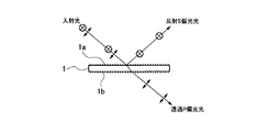
図1は、本発明に係る反射型偏光子の構成を示す側面図である。 FIG. 1 is a side view showing a configuration of a reflective polarizer according to the present invention.
本発明に係る反射型偏光子は、図1に示すように、光学ガラスからなる光透過性の基板1を有している。この基板1をなす光学ガラスとしては、種々のいわゆる白色光学ガラスを用いることができる。 As shown in FIG. 1, the reflective polarizer according to the present invention has a light-transmitting substrate 1 made of optical glass. As the optical glass forming the substrate 1, various so-called white optical glasses can be used.
そして、基板1の両主面部には、それぞれワイヤーグリッド偏光膜1a,1bが形成されている。ワイヤーグリッド偏光膜は、反射型偏光膜とも呼ばれているものである。これらワイヤーグリッド偏光膜1a,1bは、互いに平行ニコルの関係となされて形成されている。すなわち、これらワイヤーグリッド偏光膜1a,1bにおいて反射される光束の偏光方向は、互いに平行な方向となる。
Wire
この反射型偏光子においては、不定偏光の入射光が一方の主面部上のワイヤーグリッド偏光膜1aに入射すると、この入射光に含まれるS偏光成分は、このワイヤーグリッド偏光膜1aによって反射される。そして、入射光のP偏光成分は、反射面1aを透過し、基板1を透過し、さらに、他方の主面部上のワイヤーグリッド偏光膜1bを透過する。
In this reflective polarizer, when indefinitely polarized incident light is incident on the wire grid polarizing
この反射型偏光子においては、入射光のうち、ワイヤーグリッド偏光膜1a,1bによって反射される偏光成分は、基板1のいずれの主面部の側から入射する場合であっても、基板1内に入射することなく、基板1の表面部において反射されるので、基板1内における応力(歪み)による複屈折の影響を受けることがない。
In this reflective polarizer, the polarization component reflected by the wire
また、この反射型偏光子においては、入射光のうち、ワイヤーグリッド偏光膜1a,1bを透過する偏光成分は、基板1のいずれの主面部の側から入射する場合であっても、基板1内において基板1内における応力(歪み)による複屈折の影響を受けても、出射する主面部上のワイヤーグリッド偏光膜1a,1bを透過するときに、複屈折の影響を受けた成分が遮断される。
Further, in this reflective polarizer, the polarized light component transmitted through the wire
すなわち、基板1内においては、通常の使用状態において、光束が入射され温度が上昇し熱膨張が生じることによる内部応力の増大や、この基板1を支持、固定する図示しない枠部材等からの応力により、複屈折を生じる。このような複屈折は、この基板1を透過するP偏光成分の偏光方向を乱してしまい、楕円偏光にしてしまう。偏光状態の乱れは不均一であり、偏光を利用して画像表示を行う反射型空間光変調素子を用いた画像表示装置において大きな問題となる。 That is, in the substrate 1, in a normal use state, an increase in internal stress due to a temperature rise and thermal expansion caused by incidence of a light beam, and stress from a frame member (not shown) that supports and fixes the substrate 1. Causes birefringence. Such birefringence disturbs the polarization direction of the P-polarized light component transmitted through the substrate 1 and makes it elliptically polarized light. The disorder of the polarization state is non-uniform, which is a serious problem in an image display device using a reflective spatial light modulation element that performs image display using polarized light.
本発明に係る反射型偏光子を経た光束においては、基板1内で偏光面が乱れても、この基板1の両主面部上のワイヤーグリッド偏光膜1a,1bにより、基板1における複屈折の影響が抑制される。
In the light beam that has passed through the reflective polarizer according to the present invention, even if the polarization plane is disturbed in the substrate 1, the influence of birefringence in the substrate 1 is caused by the wire
なお、ワイヤーグリッド偏光膜の構成については、特表2002−514778号公報にも記載されている。 In addition, about the structure of a wire grid polarizing film, it describes also in Japanese translations of PCT publication No. 2002-514778.
そして、本発明に係る反射型偏光子においては、基板1は、光学ガラスからなる透明な基板が2枚貼合わせられたものとしてもよい。 In the reflective polarizer according to the present invention, the substrate 1 may be a laminate of two transparent substrates made of optical glass.
この場合には、各ワイヤーグリッド偏光膜1a,1bは、各基板の片側の主面部にそれぞれ形成されているものとしておく。そして、これら各基板同士を各ワイヤーグリッド偏光膜1a,1bが外側になるよう貼合わせるときに、各基板同士の位置関係を調整することにより、各ワイヤーグリッド偏光膜1a,1bを、容易に平行ニコルの関係とすることができる。
In this case, each wire grid
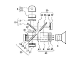
図2は、本発明に係る画像表示装置の構成を示す平面図である。 FIG. 2 is a plan view showing the configuration of the image display apparatus according to the present invention.
本発明に係る画像表示装置は、図2に示すように、光源部6と、光束分離手段となる色成分分離部10と、第1の光束分離合成手段となる第1の色成分分離合成部20と、第2の光束分離合成手段となる第2の色成分分離合成部30と、光束合成手段となる色合成部40と、結像光学系となる投写レンズ8とを有して構成されている。
As shown in FIG. 2, the image display apparatus according to the present invention includes a light source unit 6, a color
光源部6は、凹面反射板を備えたランプ61と、偏光板62とを有して構成されている。ランプ61から出射されたR(赤)G(緑)B(青)3原色光を含む白色の不定偏光光束は、偏光板62を透過することにより、概ねP偏光成分のみ、あるいは、S偏光成分のみからなる所定の偏光状態の照明光となり、色成分分離部10に入射される。
The light source unit 6 includes a
色成分分離部10は、入射された照明光を、各原色光の偏光状態に応じて、第1及び第2の原色光を含む光束と第3の原色光を含む光束とに分離させ、これら光束を互いに直交する2方向に出射する。
The color
すなわち、色成分分離部10は、光源部6からの照明光が入射される第1のカラー偏光子12と、この第1のカラー偏光子12を透過した照明光が入射される色分離用反射型偏光子11とから構成されている。光源部6から入射された照明光は、第1のカラー偏光子12において、白色光のうちの所望の波長域成分(第3の原色光)のみの偏光方向を90°回転されて、色分離用反射型偏光子11に対し、ガラス基板面から入射される。
That is, the color
この色分離用反射型偏光子11は、ガラス基板の片側のみにワイヤーグリッド偏光膜が形成されたものである。 This color separation reflective polarizer 11 is formed by forming a wire grid polarizing film only on one side of a glass substrate.
色分離用反射型偏光子11においては、第1のカラー偏光子12を透過した照明光のうちのP偏光成分(第1及び第2の原色光)が透過して第1の色成分分離合成部20に入射される。第1のカラー偏光子12を透過した照明光のうちのS偏光成分(第3の原色光)は、色分離用反射型偏光子11において反射され、この色分離用反射型偏光子11に対する入射光に直交する方向に出射されて、第2の色成分分離合成部30に入射される。
In the reflective polarizer 11 for color separation, the P-polarized component (first and second primary color light) of the illumination light transmitted through the first color polarizer 12 is transmitted and the first color component is separated and combined. Incident on the
第1の色成分分離合成部20は、色成分分離部10により分離された光束のうち、第1及び第2の原色光を含む光束が入射され、この光束を各原色光の偏光状態に応じて互いに直交する2方向に分離させて第1及び第2の反射型空間光変調素子23,24にそれぞれ入射させるとともに、これら第1及び第2の反射型空間光変調素子23,24において変調されて反射された反射光束を合成して、色成分分離部10からの光束の入射方向に対して直交する方向に出射する。
The first color component separation /
すなわち、第1の色成分分離合成部20は、色成分分離部10からの光束が入射される第2のカラー偏光子22と、この第2のカラー偏光子22の透過光が入射される反射型偏光子25と、この反射型偏光子25の透過光が入射される第1の波長板27及び第1の反射型空間光変調素子23と、反射型偏光子25における反射光が入射される第2の波長板26及び第2の反射型空間光変調素子24とを備えている。
That is, the first color component separation /
反射型偏光子25は、光学ガラスからなる光透過性の基板の両主面部に互いに平行ニコルの関係となされてワイヤーグリッド偏光膜がそれぞれ形成された構成となっている。
The
色成分分離部10の色分離用反射型偏光子11を透過したP偏光成分(第1及び第2の原色光)は、第2のカラー偏光子22において、所望の波長域成分(第1または第2の原色光)のみの偏光方向を90°回転されて、反射型偏光子25に入射される。第2のカラー偏光子22において偏光方向を90°回転された成分は、反射型偏光子25に対するS偏光成分となり、この反射型偏光子25の反射面により反射され、第2の反射型空間光変調素子24に入射される。
The P-polarized component (first and second primary color light) transmitted through the color separation reflective polarizer 11 of the color
一方、第2のカラー偏光子22において偏光方向を回転されずに透過した成分は、反射型偏光子25に対するP偏光成分となり、この反射型偏光子25を透過し、第1の反射型空間光変調素子23に入射される。
On the other hand, the component transmitted through the
第1の反射型空間光変調素子23及び第2の反射型空間光変調素子24に入射された光束は、表示画像に応じて偏光方向を変調されて反射される。表示画像において明るい画素の部分では、入射光の偏光方向が90°回転されて反射され、暗い画素の部分では、入射光の偏光方向がそのままで反射される。
The light beams incident on the first reflective spatial light modulation element 23 and the second reflective spatial
すなわち、第1の反射型空間光変調素子23に入射されたP偏光成分は、表示画像に応じてS偏光成分となって反射され、反射型偏光子25において反射されて色成分合成部40に入射される。そして、偏光方向を変調されなかったP偏光成分は、反射型偏光子25を透過して、色成分分離部10に戻り、光源部6へ戻される。
That is, the P-polarized component incident on the first reflective spatial light modulator 23 is reflected as an S-polarized component according to the display image, reflected by the
第2の反射型空間光変調素子24に入射されたS偏光成分は、表示画像に応じてP偏光成分となって反射され、反射型偏光子25を透過して色成分合成部40に入射される。そして、偏光方向を変調されなかったS偏光成分は、反射型偏光子25において反射され、色成分分離部10に戻り、光源部6へ戻される。
The S-polarized component incident on the second reflective spatial
第2の色成分分離合成部30は、色成分分離部10により分離された光束のうち、第3の原色光を含む光束が入射され、この光束を第3の反射型空間光変調素子32に入射させるとともに、この第3の反射型空間光変調素子32において変調されて反射された反射光束を、色成分分離部10からの光束の入射方向に対して直交する方向に出射する。
The second color component separation /
すなわち、第2の色成分分離合成部30は、色成分分離部10からの光束が入射される第3のカラー偏光子35と、この第3のカラー偏光子35の透過光が入射される反射型偏光子33と、この反射型偏光子33の透過光が入射される第3の波長板34及び第3の反射型空間光変調素子32とを備えている。
That is, the second color component separation /
色成分分離部10の色分離用反射型偏光子11により反射されたS偏光成分(第3の原色光)は、第3のカラー偏光子35において、偏光方向を90°回転されて、反射型偏光子33に対し、ガラス基板面から入射される。この反射型偏光子33は、ガラス基板の片側のみにワイヤーグリッド偏光膜が形成されたものである。なお、第3のカラー偏光子35は、λ/2板(二分の一波長板)としてもよい。反射型偏光子33への入射光は、この反射型偏光子33に対するS偏光成分となっており、この反射型偏光子33を透過し、第3の反射型空間光変調素子32に入射される。
The S-polarized component (third primary color light) reflected by the color separation reflective polarizer 11 of the color
第3の反射型空間光変調素子32に入射されたP偏光成分は、表示画像に応じてS偏光成分となって反射され、反射型偏光子33において反射されて色成分合成部40に入射される。そして、偏光方向を変調されなかったP偏光成分は、反射型偏光子33を透過して、色成分分離部10に戻り、光源部6へ戻される。
The P-polarized component incident on the third reflective spatial
色合成部40は、第1の色成分分離合成部20からの出射光束及び第2の色成分分離合成部30からの出射光束が入射され、これら光束を合成して、投写レンズ8に入射させる。
The
すなわち、色合成部40は、第1の色成分分離合成部20からの光束が入射される第4のカラー偏光子43と、この第4のカラー偏光子43の透過光及び第2の色成分分離合成部30からの光束が入射される色合成用の偏光ビームスプリッタ41と、この偏光ビームスプリッタ41を経た光束が入射される第5のカラー偏光子44及び偏光板45とを備えている。
That is, the
この色合成部40において、第2の色成分分離合成部30から入射されたS偏光成分は、偏光ビームスプリッタ41の偏光反射面において反射され、投射レンズ8側に出射される。このとき、第2の色成分分離合成部30からの入射光の波長帯域成分(第3の原色光)の偏光方向を、第5のカラー偏光子44によって、90°回転させ、P偏光成分として、偏光板45を透過させる。
In this
一方、第1の色成分分離合成部20から入射された光束のうち第1の反射型空間光変調素子23において反射されたS偏光成分は、第4のカラー偏光子43において偏光方向を90°回転され、P偏光成分として、偏光ビームスプリッタ41の偏光膜を透過し、そのまま投射レンズ8側に出射される。
On the other hand, the S-polarized light component reflected by the first reflective spatial light modulator 23 out of the light beam incident from the first color component separating / combining
第1の色成分分離合成部20から入射された光束のうち第2の反射型空間光変調素子24において反射されたP偏光成分は、第4のカラー偏光子43を偏光方向を回転されることなく透過し、さらに、偏光ビームスプリッタ41の偏光膜を透過し、そのまま投射レンズ8側に出射される。
Of the light beam incident from the first color component separation /
この画像表示装置においては、色成分分離部10の色分離用反射型偏光子11、第1の色成分分離合成部20の反射型偏光子25及び第2の色成分分離合成部30の反射型偏光子33のうち、少なくとも第1の色成分分離合成部20の反射型偏光子25は、光学ガラスからなる光透過性の基板1の両主面部に互いに平行ニコルの関係となされてワイヤーグリッド偏光膜1a,1bがそれぞれ形成された構成となっている。したがって、この反射型偏光子25においては、基板1内における複屈折が表示画像に影響することがない。
In this image display device, the color separation reflective polarizer 11 of the color
なお、色成分分離部10の色分離用反射型偏光子11及び第2の色成分分離合成部30の反射型偏光子33も、光学ガラスからなる光透過性の基板の両主面部に互いに平行ニコルの関係となされてワイヤーグリッド偏光膜がそれぞれ形成された構成としてもよい。このように、各反射型偏光子を、基板の両面にワイヤーグリッド偏光膜を有するものとすることにより、基板内における複屈折の表示画像に対する影響をより確実に抑制することができる。
The color separation reflective polarizer 11 of the color
この画像表示装置において、第1乃至第3の反射型空間光変調素子23,24,32の入射面側に配置されている第1乃至第3波長板27,26,34は、各反射型空間光変調素子23,24,32が反射型液晶表示素子である場合において、液晶プレチルト角の偏光状態の補正を行なうためのものである。なお、これらいずれの波長板27,26,34も、各透過波長に対応したλ/4板(四分の一波長板)あるいはλ/2板(二分の一波長板)である。液晶プレチルト角分の補正は、微量でよく、1/10波長以下、さらには、1/20波長以下の微量な補正板であるほうが望ましい。
In this image display device, the first to
実際の波長板の取り付けにあたっての光学軸方向の設定は、反射型空間光変調素子を黒表示状態とし、表示される画像において黒が最も沈んだ状態(黒くなる状態)とになるようにして調整を行なう。 The setting of the optical axis direction when mounting the actual wave plate is adjusted so that the reflective spatial light modulator is in the black display state and the black is the most sunk (black state) in the displayed image. To do.
なお、図2においては、第2の反射型空間光変調素子24と反射型偏光子25との間にシリンドリカルレンズ81が配置されている。このシリンドリカルレンズ81は、第2の反射型空間光変調素子24において反射された変調光の投射レンズ8に至る光路上に反射型偏光子25の基板1が傾斜して挿入されているために、この基板1において非点収差が発生するので、この非点収差を補正するためのレンズである。
In FIG. 2, a
1 基板
1a,1b ワイヤーグリッド偏光膜
6 光源部
8 投写レンズ
10 色成分分離部
20 第1の色成分分離合成部
30 第2の色成分分離合成部
40 色合成部
DESCRIPTION OF SYMBOLS 1
Claims (2)
前記基板の両主面部にそれぞれ形成されたワイヤーグリッド偏光膜と、を備え、
前記各ワイヤーグリッド偏光膜は、互いに平行ニコルの関係となされて形成されていることを特徴とする反射型偏光子。 A light-transmitting substrate made of optical glass;
Wire grid polarizing film formed respectively on both main surface portions of the substrate,
Each of the wire grid polarizing films is formed in a parallel Nicols relationship with each other, and is a reflective polarizer.
前記光束分離手段により分離された光束のうち、第1及び第2の原色光を含む光束が入射され、この光束を各原色光の偏光状態に応じて互いに直交する2方向に分離させて第1及び第2の反射型空間光変調素子にそれぞれ入射させるとともに、これら第1及び第2の反射型空間光変調素子において変調されて反射された反射光束を合成して、前記光束分離手段からの光束の入射方向に対して直交する方向に出射する第1の光束分離合成手段と、
前記光束分離手段により分離された光束のうち、第3の原色光を含む光束が入射され、この光束を第3の反射型空間光変調素子に入射させるとともに、この第3の反射型空間光変調素子において変調されて反射された反射光束を、前記光束分離手段からの光束の入射方向に対して直交する方向に出射する第2の光束分離合成手段と、
前記第1の光束分離合成手段からの出射光束及び前記第2の光束分離合成手段からの出射光束が入射され、これら光束を合成して、結像光学系に入射させる光束合成手段と、を備え、
前記光束分離手段、前記第1の光束分離合成手段及び前記第2の光束分離合成手段のうち、少なくとも前記第1の光束分離合成手段は、光学ガラスからなる光透過性の基板の両主面部に互いに平行ニコルの関係となされてワイヤーグリッド偏光膜がそれぞれ形成されたものであることを特徴とする画像表示装置。 Illumination light including three primary color lights and having a predetermined polarization state is incident, and the illumination light is converted into a light beam including the first and second primary color light and the third primary color light according to the polarization state of each primary color light. A light beam separating means for separating the light beam into two directions orthogonal to each other;
Of the light beams separated by the light beam separating means, a light beam including first and second primary color lights is incident, and the light beams are separated into two directions orthogonal to each other in accordance with the polarization state of each primary color light to be first. And the reflected light fluxes modulated and reflected by the first and second reflective spatial light modulation elements, and combined with the reflected light fluxes from the light flux separating means. First light beam separating / combining means for emitting light in a direction orthogonal to the incident direction of
Of the light beams separated by the light beam separating means, a light beam containing the third primary color light is incident, and this light beam is incident on the third reflective spatial light modulation element, and this third reflective spatial light modulation is performed. A second light beam separating / combining unit that emits a reflected light beam modulated and reflected by the element in a direction orthogonal to an incident direction of the light beam from the light beam separating unit;
A light beam combining unit that receives the light beam emitted from the first light beam separation / combination unit and the light beam output from the second light beam separation / combination unit, combines the light beams, and enters the imaging optical system; ,
Of the light beam separating means, the first light beam separating / combining means, and the second light beam separating / combining means, at least the first light beam separating / combining means is formed on both main surface portions of a light-transmitting substrate made of optical glass. An image display device characterized in that a wire grid polarizing film is formed in a parallel Nicol relationship.
Priority Applications (1)
| Application Number | Priority Date | Filing Date | Title |
|---|---|---|---|
| JP2003337505A JP2005106940A (en) | 2003-09-29 | 2003-09-29 | Reflection type polarizer and image display device |
Applications Claiming Priority (1)
| Application Number | Priority Date | Filing Date | Title |
|---|---|---|---|
| JP2003337505A JP2005106940A (en) | 2003-09-29 | 2003-09-29 | Reflection type polarizer and image display device |
Publications (1)
| Publication Number | Publication Date |
|---|---|
| JP2005106940A true JP2005106940A (en) | 2005-04-21 |
Family
ID=34533307
Family Applications (1)
| Application Number | Title | Priority Date | Filing Date |
|---|---|---|---|
| JP2003337505A Pending JP2005106940A (en) | 2003-09-29 | 2003-09-29 | Reflection type polarizer and image display device |
Country Status (1)
| Country | Link |
|---|---|
| JP (1) | JP2005106940A (en) |
Cited By (5)
| Publication number | Priority date | Publication date | Assignee | Title |
|---|---|---|---|---|
| JP2007233293A (en) * | 2006-03-03 | 2007-09-13 | Compal Communications Inc | Projector and portable electronic device having the same |
| JP2008216956A (en) * | 2006-07-07 | 2008-09-18 | Sony Corp | Polarizing element and liquid crystal projector |
| JP2009276401A (en) * | 2008-05-12 | 2009-11-26 | Teijin Ltd | Laminated sheet polarizer and liquid crystal display device |
| JP2010210705A (en) * | 2009-03-06 | 2010-09-24 | Seiko Epson Corp | Polarizing element and method of manufacturing the same, projection type display device, liquid crystal device, and electronic device |
| USRE45642E1 (en) | 2007-02-06 | 2015-08-04 | Sony Corporation | Polarizing element and liquid crystal projector |
-
2003
- 2003-09-29 JP JP2003337505A patent/JP2005106940A/en active Pending
Cited By (10)
| Publication number | Priority date | Publication date | Assignee | Title |
|---|---|---|---|---|
| JP2007233293A (en) * | 2006-03-03 | 2007-09-13 | Compal Communications Inc | Projector and portable electronic device having the same |
| JP2008216956A (en) * | 2006-07-07 | 2008-09-18 | Sony Corp | Polarizing element and liquid crystal projector |
| JP2012048258A (en) * | 2006-07-07 | 2012-03-08 | Sony Corp | Polarizing element and liquid crystal projector |
| JP2019003209A (en) * | 2006-07-07 | 2019-01-10 | ソニー株式会社 | Liquid crystal projector |
| USRE45642E1 (en) | 2007-02-06 | 2015-08-04 | Sony Corporation | Polarizing element and liquid crystal projector |
| USRE46560E1 (en) | 2007-02-06 | 2017-09-26 | Sony Corporation | Polarizing element and liquid crystal projector |
| USRE48640E1 (en) | 2007-02-06 | 2021-07-13 | Dexerials Corporation | Polarizing element and liquid crystal projector |
| JP2009276401A (en) * | 2008-05-12 | 2009-11-26 | Teijin Ltd | Laminated sheet polarizer and liquid crystal display device |
| JP2010210705A (en) * | 2009-03-06 | 2010-09-24 | Seiko Epson Corp | Polarizing element and method of manufacturing the same, projection type display device, liquid crystal device, and electronic device |
| US8488070B2 (en) | 2009-03-06 | 2013-07-16 | Seiko Epson Corporation | Polarizing element and method for manufacturing the same, projection type display, liquid crystal device, and electronic apparatus |
Similar Documents
| Publication | Publication Date | Title |
|---|---|---|
| US6678015B2 (en) | Color separating/synthesizing apparatus | |
| JP3417757B2 (en) | Liquid crystal display device and light beam separating method thereof | |
| JP2008275798A (en) | Projection-type display apparatus | |
| US6943850B2 (en) | Optical apparatus and projection type display apparatus for reducing a physical distance between a light source and a display | |
| JP2009229804A (en) | Optical component, optical unit and display | |
| US7137704B2 (en) | Color splitting/combining optical system and image projecting apparatus | |
| US7092056B2 (en) | Quarter wavelength plate and projection type video display device using the same | |
| JP4380180B2 (en) | Image display device | |
| CN111902771B (en) | Image display device and image display unit | |
| JP2006276826A (en) | Reflection type projection display apparatus | |
| US7365721B2 (en) | Projection display | |
| JP2005106940A (en) | Reflection type polarizer and image display device | |
| US6123424A (en) | Optical system for use in an image projector | |
| JP2000111864A (en) | Projection display device and method of adjusting projection display device | |
| JP2011059461A (en) | Projection display device | |
| KR100429213B1 (en) | optics system of projector | |
| JP2008275909A (en) | Projection display device | |
| JP2011095404A (en) | Image display device | |
| JP4967253B2 (en) | Optical device and projection device | |
| JP2007199486A (en) | Projection type display device | |
| JP2005099093A (en) | Polarization separating device and projection display device | |
| CN113841088B (en) | Image display device and image display unit | |
| JP2000112020A (en) | Projection type display device | |
| JP2007003809A (en) | Projection image display apparatus | |
| JP2005134814A (en) | Image display device |
Legal Events
| Date | Code | Title | Description |
|---|---|---|---|
| A621 | Written request for application examination |
Free format text: JAPANESE INTERMEDIATE CODE: A621 Effective date: 20060331 |
|
| A131 | Notification of reasons for refusal |
Free format text: JAPANESE INTERMEDIATE CODE: A131 Effective date: 20081104 |
|
| A02 | Decision of refusal |
Free format text: JAPANESE INTERMEDIATE CODE: A02 Effective date: 20090317 |