JP2005106901A - Image projection device - Google Patents
Image projection device Download PDFInfo
- Publication number
- JP2005106901A JP2005106901A JP2003336904A JP2003336904A JP2005106901A JP 2005106901 A JP2005106901 A JP 2005106901A JP 2003336904 A JP2003336904 A JP 2003336904A JP 2003336904 A JP2003336904 A JP 2003336904A JP 2005106901 A JP2005106901 A JP 2005106901A
- Authority
- JP
- Japan
- Prior art keywords
- light
- liquid crystal
- display element
- reflective liquid
- crystal display
- Prior art date
- Legal status (The legal status is an assumption and is not a legal conclusion. Google has not performed a legal analysis and makes no representation as to the accuracy of the status listed.)
- Withdrawn
Links
Images

Landscapes
- Liquid Crystal (AREA)
- Projection Apparatus (AREA)
Abstract
【課題】 反射型液晶表示素子が黒を表示した時の戻り光が光源に戻らないようにすることで、光源部の温度上昇を防ぐことができる。
【解決手段】 赤、緑、青用の3つの反射型液晶パネルと、光源からの光を2つの偏光ビームスプリッターを用いて3つの反射型液晶パネルを照明する照明光学系と、前記反射型液晶パネルからの光をスクリーンに投影する投影光学系とを有する画像投射装置であって、可視光領域よりも短い周期の周期構造(SWS)を有する1/4波長板を前記2つの偏光ビームスプリッターと前記3つの反射型液晶パネルとの間に配置する。
【選択図】 図1
PROBLEM TO BE SOLVED: To prevent a temperature rise of a light source part by preventing return light when a reflective liquid crystal display element displays black from returning to the light source.
SOLUTION: Three reflective liquid crystal panels for red, green, and blue, an illumination optical system that illuminates three reflective liquid crystal panels using two polarization beam splitters with light from a light source, and the reflective liquid crystal A projection optical system that projects light from a panel onto a screen, and a quarter-wave plate having a periodic structure (SWS) having a period shorter than a visible light region is used as the two polarizing beam splitters. Arranged between the three reflective liquid crystal panels.
[Selection] Figure 1
Description
本発明は画像投射装置に関する。 The present invention relates to an image projection apparatus.
反射型液晶表示装置を用いた画像投射装置において、光源からの光を偏光ビームスプリッターを介して反射型液晶表示素子に導き、反射型液晶表示素子を反射した光を再び偏光ビームスプリッターで検光し投射する構成で、前記偏光ビームスプリッターと前記反射型液晶表示素子の間に1/4位相板を設け、コントラスト調整を行う実施形態が特公平07-028050に開示されている(図9)。 In an image projection device using a reflective liquid crystal display device, the light from the light source is guided to the reflective liquid crystal display device via the polarizing beam splitter, and the light reflected from the reflective liquid crystal display device is analyzed again by the polarizing beam splitter. Japanese Patent Publication No. 07-028050 discloses an embodiment in which a 1/4 phase plate is provided between the polarizing beam splitter and the reflective liquid crystal display element in a projecting configuration to perform contrast adjustment (FIG. 9).
ここで画像投射装置で投射する画像の明るさをより明るくするためには、均一な照明領域を形成するための光束分離手段と照明光の偏光方向をそろえるための偏光変換手段を有し、偏光変換手段を射出する複数の光束を集光する集光光学系が必要となり、かつこれらからなる照明系の利用効率を高くするためには集光光学系のFnoを小さくする必要があり、これにより反射型画像表示素子上の任意の1点に集光する光束の最大入射角度はより大きくする必要がある。 Here, in order to make the brightness of the image projected by the image projection apparatus brighter, it has a light beam separation means for forming a uniform illumination area and a polarization conversion means for aligning the polarization direction of the illumination light. A condensing optical system for condensing a plurality of light beams emitted from the conversion means is required, and in order to increase the utilization efficiency of the illumination system composed of these, it is necessary to reduce the Fno of the condensing optical system. It is necessary to increase the maximum incident angle of the light beam condensed at an arbitrary point on the reflective image display element.
しかしながら、1/4位相板は所定の厚みを有する構造体であるので、1/4位相板に対して大きな角度で入射する光に対しては位相板としての特性が1/4位相からずれてしまい、コントラスト調整を行っても十分なコントラストが得られないという問題があった。 However, because the 1/4 phase plate is a structure having a predetermined thickness, the characteristics of the phase plate are shifted from the 1/4 phase for light incident at a large angle with respect to the 1/4 phase plate. As a result, there is a problem that sufficient contrast cannot be obtained even when contrast adjustment is performed.
上記課題を解決ずるために、本発明の画像投射装置は、少なくとも1つの画像表示素子と、光源からの光を用いて前記少なくとも1つの液晶表示素子を照明する照明光学系と、前記少なくとも1つの画像表示素子からの光を被投影面に投影する投影光学系とを有する画像投射装置であって、使用波長よりも短い周期の周期構造を有する位相板を有することを特徴としている。 In order to solve the above-described problems, an image projection apparatus according to the present invention includes at least one image display element, an illumination optical system that illuminates the at least one liquid crystal display element using light from a light source, and the at least one image display device. An image projection apparatus having a projection optical system that projects light from an image display element onto a projection surface, and having a phase plate having a periodic structure having a period shorter than a used wavelength.
ここで、前記位相板は1/4波長板であることが望ましい。前記少なくとも1つの画像表示素子が、赤用の反射型液晶表示素子、緑用の反射型液晶表示素子、青用の反射型液晶表示素子であることが好ましい。また、前記照明光学系が、前記光源からの光を複数の波長領域の光に分解する色分解光学系を備えていると尚良い。 Here, the phase plate is preferably a quarter wave plate. The at least one image display element is preferably a red reflective liquid crystal display element, a green reflective liquid crystal display element, or a blue reflective liquid crystal display element. The illumination optical system may further include a color separation optical system that separates light from the light source into light in a plurality of wavelength regions.
また、前記色分解光学系と前記少なくとも1つの画像表示素子との間に、前記位相板を配置することが望ましい。 It is desirable that the phase plate is disposed between the color separation optical system and the at least one image display element.
また、前記色分解光学系が有する偏光分離部材と前記少なくとも1つの画像表示素子との間の光路上に、前記位相板が配置されていることが望ましい。 Further, it is desirable that the phase plate is disposed on an optical path between the polarization separation member included in the color separation optical system and the at least one image display element.
また、前記少なくとも1つの画像表示素子が、3つの反射型液晶表示素子であり、前記色分解光学系が2つの偏光分離部材を有しており、前記2つの偏光分離部材と前記3つの反射型液晶表示素子との間には、それぞれ前記位相板が配置されていることが望ましい。 Further, the at least one image display element is three reflective liquid crystal display elements, the color separation optical system has two polarization separation members, the two polarization separation members and the three reflection types. It is desirable that the phase plates are respectively disposed between the liquid crystal display elements.
ここで、前記3枚の位相板はそれぞれ、3つの反射型液晶表示素子に対して離間されて配置されていることが望ましい。また、前記3枚の位相板はそれぞれ、前記2つの偏光分離部材に対して離間されて配置されていても良い。また、前記3枚の位相板は、それぞれ互いに異なる光学特性を有するように構成しても良い。また、前記3枚の位相板のうち2枚は実質的に同じ光学特性を有しており(もしくは2枚の位相板は同じ構成を有するものとしても構わない。残りの1枚の位相板は他の2枚の位相板と比べて異なる光学特性を有するように構成しても良い。ここでは、前記残りの1枚の位相板は、赤用の反射型液晶表示素子と前記2つの偏光分離部材のうちの1つとの間に配置されていても良いし、前記残りの1枚の位相板は、青用の反射型液晶表示素子と前記2つの偏光分離部材のうちの1つとの間に配置されていても良いし、前記残りの1枚の位相板は、緑用の反射型液晶表示素子と前記2つの偏光分離部材のうちの1つとの間に配置されている。また、前記3枚の位相板は実質的に同じ光学特性を有していても良い。 Here, it is desirable that each of the three phase plates is spaced apart from the three reflective liquid crystal display elements. Further, each of the three phase plates may be spaced apart from the two polarization separation members. Further, the three phase plates may be configured to have different optical characteristics. Also, two of the three phase plates have substantially the same optical characteristics (or the two phase plates may have the same configuration. The remaining one phase plate It may be configured to have different optical characteristics compared to the other two phase plates, where the remaining one phase plate is a reflective liquid crystal display element for red and the two polarization separations. The other phase plate may be disposed between one of the members, and the remaining one phase plate may be disposed between the blue reflective liquid crystal display element and one of the two polarization separation members. The remaining one phase plate may be disposed between the green reflective liquid crystal display element and one of the two polarization separation members. The phase plates of the sheets may have substantially the same optical characteristics.
前記色分解光学系がダイクロイックミラーを有しており、該ダイクロイックミラーにより緑色光を、赤色光、青色光に対して分離するように構成すると望ましい。 It is desirable that the color separation optical system has a dichroic mirror, and the dichroic mirror separates green light from red light and blue light.
ここで、前記使用波長とは、可視光領域であり、実質的に400nm〜700nmを含む波長領域のことであると尚良い。 Here, the used wavelength is a visible light region, and is preferably a wavelength region substantially including 400 nm to 700 nm.
また、本発明によれば、位相板を断面が段差形状を有する格子形状とし、段差における光路差を所定の波長λ0の1/4波長に設定し、格子のピッチpを波長λ0よりも小さくすることにより、位相板に入射する光が任意の入射角度であっても一様に1/4位相差を与えることが可能となる。これにより照明光のFnoを小さく(照明光の広がり角度を大きく)することができ、コントラストの高い状態で投射する明るさを明るくすることが可能となる。 Further, according to the present invention, the phase plate has a grating shape having a stepped cross section, the optical path difference at the step is set to a quarter wavelength of the predetermined wavelength λ0, and the grating pitch p is made smaller than the wavelength λ0. As a result, even if the light incident on the phase plate has an arbitrary incident angle, a 1/4 phase difference can be given uniformly. As a result, the Fno of the illumination light can be reduced (the spread angle of the illumination light is increased), and the brightness to be projected in a high contrast state can be increased.
位相板の角度特性が改善し、明るい照明光束に対しても適切な調整ができ、明るくコントラストの高い投射装置が実現できる。 The angle characteristics of the phase plate are improved, and appropriate adjustment can be made even for bright illumination light flux, and a bright and high-contrast projection device can be realized.
(実施例1)
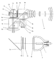
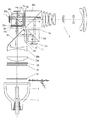
図1は本発明の第1の実施例を表す図である。図中、1は連続スペクトルで白色光を発光する光源で、2は光を所定の方向に集光するリフレクターで、3aは矩形のレンズをマトリックス状に配置した第1のフライアイレンズで、3bは第1のフライアイレンズの個々のレンズに対応したレンズアレイからなる第2のフライアイレンズで、4は無偏光光を所定の偏光光に揃える偏光変換素子で、5aはコンデンサーレンズで、5bはフィールドレンズで、5cは反射ミラーで、6a、6bはRの光の偏光方向を90度変換し、Bの光の偏光方向は変換しない第1の色選択性位相差板、第2の色選択性位相差板で、7はGの光の偏光方向を90度変換し、B,Rの光の偏光方向は変換しない第3の色選択性位相差板で、8a、8bは第1の1/2波長板、第2の1/2波長板で、9a、9b、9c、9dはP偏光を透過し、S偏光を反射する第1の偏光ビームスプリッター、第2の偏光ビームスプリッター、第3の偏光ビームスプリッター、第4の偏光ビームスプリッターで、10はGとRの中間の波長領域の光をカットするカラーフィルターで、11r、11g、11bは光を反射し、画像変調して画像を表示する赤用の反射型液晶表示素子、緑用の反射型液晶表示素子、青用の反射型液晶表示素子で、12r、12g、12bは赤用の1/4波長板、緑用の1/4波長板、青用の1/4波長板で、13は投射レンズである。
(Example 1)
FIG. 1 is a diagram showing a first embodiment of the present invention. In the figure, 1 is a light source that emits white light with a continuous spectrum, 2 is a reflector that collects light in a predetermined direction, 3a is a first fly-eye lens in which rectangular lenses are arranged in a matrix, 3b Is a second fly-eye lens composed of a lens array corresponding to each lens of the first fly-eye lens, 4 is a polarization conversion element for aligning non-polarized light with predetermined polarized light, 5a is a condenser lens, 5b Is a field lens, 5c is a reflecting mirror, 6a and 6b are a first color-selective retardation plate that converts the polarization direction of the R light by 90 degrees and does not convert the polarization direction of the B light, and the second color. A selective phase difference plate 7 is a third color selective phase plate 7 that converts the polarization direction of G light by 90 degrees and does not convert the polarization direction of B and R light. 9a, 9b, 9c, and 9d transmit P-polarized light and S-polarized light. A first polarizing beam splitter that reflects light, a second polarizing beam splitter, a third polarizing beam splitter, and a fourth polarizing beam splitter, and 10 is a color filter that cuts light in the wavelength region between G and
次に光学的な作用を説明する。光源1から発した光はリフレクター2により所定の方向に集光される。ここでリフレクター2は放物面形状をなしており、放物面の焦点位置からの光は放物面の対称軸に平行な光束となる。ただし、光源1は理想的な点光源ではなく有限の大きさを有しているので、集光する光束には放物面の対称軸に平行でない光の成分も多く含まれている。これらの集光光束は第1のフライアイレンズ3aに入射する。第1のフライアイレンズ3aは外形が矩形の正の屈折力を有するレンズをマトリックス状に組み合わせて構成されており、入射した光束はそれぞれのレンズに応じた複数の光束に分割され、かつ集光され、第2のフライアイレンズ3bを経て、マトリックス状に複数の光源像を偏光変換素子の近傍に形成する。偏光変換素子4は偏光分離面と反射面と1/2波長板からなり、マトリックス状に集光する複数の光束はその列に対応した偏光分離面に入射し、透過するP偏光成分の光と反射するS偏光成分の光に分割される。反射されたS偏光成分の光は反射面で反射し、P偏光成分と同じ方向に出射し、1/2波長板を透過しP偏光成分と同じ偏光成分に変換され、偏光方向(|)が揃った光として射出する。偏光変換された複数の光束は偏光変換素子の近傍で集光した後、発散光束として集光光学系に至る。集光光学系は、コンデンサーレンズ5aとフィールドレンズ5bからなる。複数の光束は集光光学系によりフライアイレンズの矩形形状の像ができる位置でそれぞれ重なり、矩形の均一な照明エリアを形成する。この照明エリアに反射型液晶表示素子11r、11g、11bを配置する。
Next, the optical action will be described. Light emitted from the light source 1 is collected in a predetermined direction by the
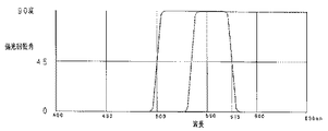
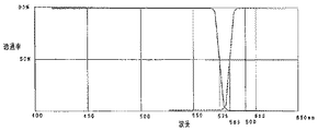
照明光路中に設けられた第3の色選択性位相差板7は図2の実線で示すような特性を有しており、BとRの光はP偏光(|)のままで、Gの光はS偏光(・)に変換される。ここでいう偏光方向(・)(|)は偏光変換素子及び偏光ビームスプリッターの偏光分離面に対する偏光の方向として表している。 The third color-selective phase difference plate 7 provided in the illumination optical path has characteristics as shown by the solid line in FIG. 2, and the B and R light remains as P-polarized light (|), and G Light is converted to S-polarized light (•). The polarization direction (·) (|) here is expressed as the direction of polarization with respect to the polarization separation plane of the polarization conversion element and the polarization beam splitter.
第3の色選択性位相差板7において偏光方向を調整された光は第1の偏光ビームスプリッター9aに入射する。S偏光であるGの光は偏光分離面を反射し、P偏光であるR,Bの光は偏光面を透過することで色分離が行われる。 The light whose polarization direction is adjusted in the third color selective phase difference plate 7 enters the first polarization beam splitter 9a. The G light that is S-polarized light reflects the polarization separation surface, and the R and B light that is P-polarized light passes through the polarization surface for color separation.
色分離されたGの光は第2の偏光ビームスプリッター9bに対してS偏光(・)として入射し、偏光分離面を反射し、G用の反射型液晶表示素子11gへと至る。G用の反射型液晶表示素子11gにおいてGの光が画像変調されて反射される。画像変調されたGの反射光のS偏光成分(・)は再び偏光分離面を反射し、光源側に戻され投射光から除去される。画像変調されたGの反射光のP偏光成分(|)は偏光分離面を透過し投射光となる。このときすべての偏光成分をS偏光に変換した状態(黒を表示した状態)において第2の偏光ビームスプリッター9bとG用の反射型液晶表示素子11gの間に設けられた1/4波長板12gの遅相軸を所定の方向に調整し、第1の偏光ビームスプリッターとG用の反射型液晶表示素子で発生する偏光状態の乱れの影響を小さく抑えている。 The color-separated G light enters the second polarizing beam splitter 9b as S-polarized light (·), reflects off the polarization separation surface, and reaches the G reflective liquid crystal display element 11g. The G light is image-modulated and reflected by the reflective liquid crystal display element 11g for G. The S-polarized component (·) of the G-modulated reflected light of the image is reflected again on the polarization separation surface, returned to the light source side, and removed from the projection light. The P-polarized component (|) of the image-modulated G reflected light is transmitted through the polarization separation surface and becomes projection light. At this time, a ¼ wavelength plate 12g provided between the second polarization beam splitter 9b and the reflective liquid crystal display element 11g for G in a state in which all polarized components are converted to S-polarized light (a state in which black is displayed). The slow axis is adjusted in a predetermined direction to suppress the influence of the disturbance of the polarization state generated in the first polarizing beam splitter and the reflective liquid crystal display element for G.
第2の偏光ビームスプリッターを透過した光(|)は、偏光方向と45度の方向に遅相軸がなるように配置された第1の1/2波長板8aを透過し、第4の偏光ビームスプリッターに対してS偏光(・)として入射し、偏光分離面を反射し、投射レンズ13へと至る。
The light (|) transmitted through the second polarization beam splitter is transmitted through the first half-wave plate 8a arranged so as to have a slow axis in the direction of 45 degrees with respect to the polarization direction. The light enters the beam splitter as S-polarized light (·), reflects off the polarization separation surface, and reaches the
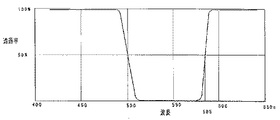
第1の偏光ビームスプリッターを透過したRとBの光(|)は、カラーフィルターに入射する。カラーフィルターは図3の実線で示すような特性を有しており、GとRの中間の波長領域にあたる黄色の色光と不要な緑の色光を反射するダイクロイックフィルターとしている。 The R and B light (|) transmitted through the first polarizing beam splitter is incident on the color filter. The color filter has characteristics as indicated by the solid line in FIG. 3, and is a dichroic filter that reflects yellow color light and unnecessary green color light in the middle wavelength region between G and R.
また、カラーフィルターは光を吸収する特性でもよい。 The color filter may have a characteristic of absorbing light.
色を調整された光は、第1の色選択性位相差板6aに入射する。第1の色選択性位相差板6aは図2の点線で示すような特性を有しており、Bの光はP偏光(|)のままで、Rの光はS偏光(・)に変換される。ここで偏光状態が変化する遷移領域はGの領域に設定している。
The light whose color has been adjusted is incident on the first color selective
これによりBの光はP偏光(|)として、Rの光はS偏光(・)として第3の偏光ビームスプリッター9cに入射する。よって第3の偏光ビームスプリッター9cにおいてBの光は偏光分離面を透過してB用の反射型液晶表示素子11bに至り、Rの光は偏光分離面を反射してR用の反射型液晶表示素子11rに至る。
As a result, the B light enters the third polarization beam splitter 9c as P-polarized light (|) and the R light as S-polarized light (·). Therefore, in the third polarizing beam splitter 9c, the B light is transmitted through the polarization separation surface and reaches the B reflective liquid
B用の反射型液晶表示素子においてBの光が画像変調されて反射される。変調されたBの反射光のP偏光成分(|)は再び偏光分離面を透過し、光源側に戻され投射光から除去される。変調されたBの反射光のS偏光成分(・)は偏光分離面で反射し投射光となる。同様にR用の反射型液晶表示素子においてRの光が画像変調されて反射される。変調されたRの反射光のS偏光成分(・)は再び偏光分離面を反射し、光源側に戻され投射光から除去される。変調されたRの反射光のP偏光成分(|)は偏光分離面を透過し投射光となる。これによりBとRの投射光は一つの光束に合成される。このとき、第3の偏光ビームスプリッター9cとR用、B用の反射型液晶表示素子11r、11bの間に設けられた1/4波長板12r、12bの遅相軸を調整してGの場合と同じようにR、Bそれぞれの黒の表示の調整を行う。
In the reflective liquid crystal display element for B, B light is image-modulated and reflected. The P-polarized light component (|) of the modulated reflected light of B is transmitted again through the polarization separation surface, returned to the light source side, and removed from the projection light. The S-polarized light component (•) of the modulated B reflected light is reflected by the polarization separation surface and becomes projection light. Similarly, R light is image-modulated and reflected by the reflective liquid crystal display element for R. The S-polarized light component (•) of the modulated R reflected light is reflected again from the polarization separation surface, returned to the light source side, and removed from the projection light. The P-polarized light component (|) of the modulated reflected light of R is transmitted through the polarization separation surface and becomes projection light. As a result, the B and R projection lights are combined into one light beam. At this time, G is adjusted by adjusting the slow axis of the quarter wave plates 12r and 12b provided between the third polarizing beam splitter 9c and the reflective liquid
合成されたRとBの投射光は第2の色選択性位相差板に入射する。第2の色選択性位相差板は第1の色選択性位相差板と同じものでRの偏光方向のみを90度回転し、R、BともにS偏光(・)に変換される。さらに偏光方向に対して45度方向に遅相軸を配置した1/2位相板8bによりそれぞれP偏光(|)に変換され第4の偏光ビームスプリッター4dに入射し、偏光分離面を透過することでGの投射光と合成される。
The combined R and B projection light is incident on the second color selective phase difference plate. The second color-selective phase difference plate is the same as the first color-selective phase difference plate, rotates only the polarization direction of R by 90 degrees, and both R and B are converted to S-polarized light (•). Further, the light is converted into P-polarized light (|) by a half-
合成されたRGBの投射光は投射レンズによりスクリーンなどに投影される。 The combined RGB projection light is projected onto a screen or the like by a projection lens.
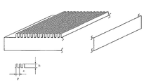
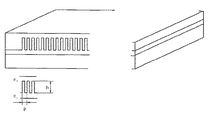
ここで、偏光ビームスプリッター9b,9cと反射型液晶表示素子11r、11g、11bの間に設ける位相板12r、12g、12bは図4に示すように格子構造としている。このとき格子の媒質の屈折率nを2.4とし、色光の基準波長λoを550nmとし、格子のピッチpをλo/2の275nm、格子の凸部のピッチをλo/4の132.5nmとしたとき、格子に平行な方向の等価屈折率nTEは
f=P'/P=0.5
nTE 2=f・n2+(1−f)=3.38
nTE=1.838
となり、格子に垂直な方向の等価屈折率nTMは
1/nTM 2=f・(1/n2)+(1−f)=0.587
nTM=1.305
となる。これにより格子の段差は
h=λo/4/(nTE−nTM)=256nm
となっている。
Here, the phase plates 12r, 12g, and 12b provided between the polarizing beam splitters 9b and 9c and the reflective liquid
n TE 2 = f · n 2 + (1−f) = 3.38
n TE = 1.838
The equivalent refractive index n TM in the direction perpendicular to the grating is 1 / n TM 2 = f · (1 / n 2 ) + (1−f) = 0.588
n TM = 1.305
It becomes. As a result, the step of the grating is h = λo / 4 / (n TE −n TM ) = 256 nm.
It has become.
図4の位相板では基板を直接格子状にしているが、図5に示すように平行平板を基板として平面状に格子構造を転写するような構成でも同様な効果が得られる。 In the phase plate of FIG. 4, the substrate is directly formed in a lattice shape, but the same effect can be obtained by a configuration in which the lattice structure is transferred in a planar shape using a parallel plate as a substrate as shown in FIG.
(実施例2)
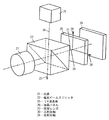
図6は本発明の第2の実施例を表す図である。図中、実施例1と同じ素子には同一の符号を記しており、24はS偏光に偏光方向を揃える偏光変換素子で、25aは第1のコンデンサーレンズで、25bは第2のコンデンサーレンズで、25c、25c’はフィールドレンズで、26は青(B)と緑(G)の波長領域の光を透過し、赤(R)の波長領域の光を反射するダイクロイックミラーで、27はGとRの中間の波長領域の光を一部カットするカラーフィルターで、28a、28bはGの光の偏光方向を90度変換し、Bの光の偏光方向は変換しない第1の色選択性位相差板、第2の色選択性位相差板で、29は所定の偏光成分を反射し、それとは直交する偏光成分を透過する偏光板で、30a、30b、30cはP偏光を透過し、S偏光を反射する第1の偏光ビームスプリッター、第2の偏光ビームスプリッター、第3の偏光ビームスプリッターで、31r、31g、31bは1/4位相板である。ここで、偏光板は不要な偏光方向を吸収するものでもよい。
(Example 2)
FIG. 6 is a diagram showing a second embodiment of the present invention. In the figure, the same elements as those in Example 1 are denoted by the same reference numerals, 24 is a polarization conversion element that aligns the polarization direction with S-polarized light, 25a is a first condenser lens, and 25b is a second condenser lens. 25c and 25c ′ are field lenses, 26 is a dichroic mirror that transmits light in the blue (B) and green (G) wavelength regions, and reflects light in the red (R) wavelength region, and 27 is G. A color filter that partially cuts light in the middle wavelength region of R. 28a and 28b convert the polarization direction of G light by 90 degrees, and the first color-selective phase difference that does not convert the polarization direction of B light. A plate, a second color-selective phase difference plate, 29 is a polarizing plate that reflects a predetermined polarization component and transmits a polarization component orthogonal thereto, and 30a, 30b, and 30c transmit P-polarization and S-polarization The first polarizing beam splitter, the second polarizing beam splitter, In the polarization beam splitter, 31r, 31g, 31b is 1/4 phase plate. Here, the polarizing plate may absorb an unnecessary polarization direction.
ダイクロイックミラー26を集光光学系を構成する第2のコンデンサーレンズ25bとフィールドレンズ25c、25c’の間に設けている。
The
次に光学的な作用を説明する。 Next, the optical action will be described.
偏光変換素子24を射出した光は、第1のコンデンサーレンズ25aと第2のコンデンサーレンズ25bにより集光され、ダイクロイックミラー26に入射する。ダイクロイックミラー26は図7の実線で示すような特性を有しており、BとGの光は透過し、Rの光は反射する。
The light emitted from the
図6においては偏光変換素子24においてS偏光(・)であった光はダイクロイックミラー26に対してもS偏光(・)である。ただし本実施例においてはダイクロイックミラー26は第2のコンデンサーレンズ25bとフィールドレンズ25c、25c’の間に設けられているので、ダイクロイックミラー26に作用する光束はテレセントリックになっていない。そのためダイクロイックミラー26は図中AからBの方向に膜厚が徐々に厚くなるような構成とし入射角度による特性の変化を補正している。
In FIG. 6, the light that has been S-polarized (•) in the
Rの光路において、ダイクロイックミラー26を反射した光はフィールドレンズ25cを透過し、カラーフィルター27に入射する。カラーフィルターは図7の点線で示すような特性を有しており、GとRの中間の波長領域にあたる黄色の色光を反射するダイクロイックフィルターとし、黄色の光を除去する。赤の光に黄色の色成分が多いと赤がオレンジになっていまうので黄色の光を除去する方が色再現上望ましい。
In the R optical path, the light reflected from the
ここでカラーフィルター27はフィールドレンズ25cと別に設けているがフィールドレンズ25cのレンズ面に設けてもよい。
Here, the
色を調整された光は、第1の偏光ビームスプリッター30aに対してS偏光(・)として入射し、偏光分離面で反射され、R用の反射型液晶表示素子11rへと至る。R用の反射型液晶表示素子11rにおいてRの光が画像変調されて反射される。変調されたRの反射光のS偏光成分(・)は再び偏光分離面で反射し、光源側に戻され投射光から除去される。変調されたRの反射光のP偏光成分(|)は偏光分離面を透過し投射光となる。第1の偏光ビームスプリッター30aを透過した光は、第1の1/2波長板8aにより偏光方向を90度回転させ、第3の偏光ビームスプリッター30cに対してはS偏光(・)として入射し、偏光分離面で反射されて、投射レンズ13へと至る。
The light whose color has been adjusted enters the first polarizing beam splitter 30a as S-polarized light (•), is reflected by the polarization separation surface, and reaches the R-use reflective liquid crystal display element 11r. The R light is image-modulated and reflected by the R reflective liquid crystal display element 11r. The S-polarized component (•) of the modulated reflected light of R is reflected again by the polarization separation surface, returned to the light source side, and removed from the projection light. The P-polarized light component (|) of the modulated reflected light of R is transmitted through the polarization separation surface and becomes projection light. The light transmitted through the first polarizing beam splitter 30a is rotated by 90 degrees in the polarization direction by the first half-wave plate 8a, and is incident on the third
このときすべての偏光成分をS偏光に変換した状態(黒を表示した状態)において第1の偏光ビームスプリッター30aとR用の反射型液晶表示素子11rの間に設けられた1/4波長板31rの遅相軸を所定の方向に調整し、第1の偏光ビームスプリッターとG用の反射型液晶表示素子で発生する偏光状態の乱れの影響を小さく抑えている。
At this time, a quarter-
ダイクロイックミラー26を透過したGとBの光は、フィールドレンズ25c’を透過し、偏光板29に入射する。偏光板29においてはダイクロイックミラー26に対してS偏光成分である偏光成分を透過し、P偏光成分である偏光成分を反射する特性を有する。偏光板29により偏光成分をより揃えた光(・)は第1の色選択性位相差板28aに入射する。第1の色選択性位相差板28aはGの光の偏光方向を90度回転する作用を持っており、これによりGの光はP偏光(|)として、Bの光はS偏光(・)として第2の偏光ビームスプリッター30bに入射する。
The G and B lights that have passed through the
B用の反射型液晶表示素子11bにおいてBの光が画像変調されて反射される。変調されたBの反射光のS偏光成分(・)は再び偏光分離面を反射し、光源側に戻され投射光から除去される。変調されたBの反射光のP偏光成分(|)は偏光分離面を透過し投射光となる。同様にG用の反射型液晶表示素子11gにおいてGの光が画像変調されて反射される。変調されたGの反射光のP偏光成分(|)は再び偏光分離面を透過し、光源側に戻され投射光から除去される。変調されたGの反射光のS偏光成分(・)は偏光分離面を反射し投射光となる。これによりBとGの投射光は一つの光束に合成される。
The B light is image-modulated and reflected by the B reflective liquid
このとき、第2の偏光ビームスプリッター30bとG用、B用の反射型液晶表示素子11g、11bの間に設けられた1/4波長板31g、31bの遅相軸を調整してRの場合と同じようにG、Bそれぞれの黒の表示の調整を行う。
At this time, when the slow axis of
合成されたGとBの投射光は第2の色選択性位相差板28bに入射する。第2の色選択性位相差板28bは第1の色選択性位相差板28aと同じものでGの偏光方向のみを90度回転し、第2の1/2波長板8bを経て、G、BともにP偏光(|)として第3の偏光ビームスプリッター10cに入射し、偏光分離面を透過することでRの投射光と合成される。
The combined G and B projection light is incident on the second color selective phase difference plate 28b. The second color-selective phase difference plate 28b is the same as the first color-selective
ここで、偏光ビームスプリッター30a,30bと反射型液晶表示素子11r、11g、11bの間に設ける位相板31r、31g、31bは図8に示すような格子構造としている。このとき格子に入射する角度は、照明系の広がり角度で決まり、この角度2αを14度とし、格子の媒質の屈折率n1を2.4、n2を1.3とし、色光の基準波長λoを550nmとしたとき、格子のピッチpをλo/2の275nm、格子の凸部のピッチを165nmとしたとき、格子に平行な方向の等価屈折率nTEは
f=P'/P=0.6
nTE 2=f・n12+(1−f)・n22=4.132
nTE=2.033
となり、格子に垂直な方向の等価屈折率nTMは
1/nTM 2=f・(1/n2)+(1−f)=0.422
nTM=1.540
となる。これにより格子の段差は
h=λo/4/(nTE−nTM)=279nm
となっている。
Here, the
n TE 2 = f · n 1 2 + (1−f) · n 2 2 = 4.132
n TE = 2.033
The equivalent refractive index n TM in the direction perpendicular to the grating is 1 / n TM 2 = f · (1 / n 2 ) + (1−f) = 0.422.
n TM = 1.540
It becomes. As a result, the step of the grating is h = λo / 4 / (n TE −n TM ) = 279 nm.
It has become.
図8の位相板では平行平板を基板として平面状に第1の物質(n1)で格子構造を形成し、さらにこの格子を埋めるように第2の物質(n2)を形成する。このとき2つの物質の屈折率の波長分散を異なるように設けることにより、1/4位相板として機能する波長範囲を拡大することができる。 In the phase plate of FIG. 8, a lattice structure is formed with a first material (n1) in a planar shape using a parallel plate as a substrate, and a second material (n2) is formed so as to fill the lattice. At this time, by providing different wavelength dispersions of the refractive indexes of the two substances, the wavelength range functioning as a quarter phase plate can be expanded.
また、2つの偏光ビームスプリッターの間に設けた1/2波長板8a,8bは、相対的に交差するように構成されている偏光分離面に対して所定の角度で入射する光線に対するS偏光を保持する作用を有しているので、上記1/4波長板と同様に格子構造としてもよい。
Moreover, the half-
本発明の画像投射装置について説明してきたが、勿論上記の限りではない。本発明の実施態様について以下に記載する。 Although the image projection apparatus of the present invention has been described, of course, it is not limited to the above. Embodiments of the present invention are described below.
本実施例の画像表示装置は、少なくとも1つの画像表示素子と、光源からの光を用いて前記少なくとも1つの液晶表示素子を照明する照明光学系と、前記少なくとも1つの画像表示素子からの光を被投影面に投影する投影光学系とを有する画像投射装置であって、使用波長(可視光領域であり、実質的に400nm〜700nmを含む波長領域のこと)よりも短い周期の周期構造を有する位相板を有することを特徴としている。 The image display apparatus according to the present embodiment includes at least one image display element, an illumination optical system that illuminates the at least one liquid crystal display element using light from a light source, and light from the at least one image display element. An image projection apparatus having a projection optical system that projects onto a projection surface, and having a periodic structure with a period shorter than a used wavelength (a wavelength region that is a visible light region and substantially includes 400 nm to 700 nm) It has a phase plate.
ここで、前記位相板は1/4波長板であることが望ましい。前記少なくとも1つの画像表示素子が、赤用の反射型液晶表示素子、緑用の反射型液晶表示素子、青用の反射型液晶表示素子であることが好ましい。また、前記照明光学系が、前記光源からの光を複数の波長領域の光に分解する色分解光学系を備えていると尚良い。 Here, the phase plate is preferably a quarter wave plate. The at least one image display element is preferably a red reflective liquid crystal display element, a green reflective liquid crystal display element, or a blue reflective liquid crystal display element. The illumination optical system may further include a color separation optical system that separates light from the light source into light in a plurality of wavelength regions.
また、前記色分解光学系と前記少なくとも1つの画像表示素子との間に、前記位相板を配置することが望ましい。 It is desirable that the phase plate is disposed between the color separation optical system and the at least one image display element.
また、前記色分解光学系が有する偏光分離部材と前記少なくとも1つの画像表示素子との間の光路上に、前記位相板が配置されていることが望ましい。 Further, it is desirable that the phase plate is disposed on an optical path between the polarization separation member included in the color separation optical system and the at least one image display element.
また、前記少なくとも1つの画像表示素子が、3つの反射型液晶表示素子であり、前記色分解光学系が2つの偏光分離部材を有しており、前記2つの偏光分離部材と前記3つの反射型液晶表示素子との間には、それぞれ前記位相板が配置されていることが望ましい。 Further, the at least one image display element is three reflective liquid crystal display elements, the color separation optical system has two polarization separation members, the two polarization separation members and the three reflection types. It is desirable that the phase plates are respectively disposed between the liquid crystal display elements.
ここで、前記3枚の位相板はそれぞれ、3つの反射型液晶表示素子に対して離間されて配置されていることが望ましい。また、前記3枚の位相板はそれぞれ、前記2つの偏光分離部材に対して離間されて配置されていても良い。また、前記3枚の位相板は、それぞれ互いに異なる光学特性を有するように構成しても良い。また、前記3枚の位相板のうち2枚は実質的に同じ光学特性を有しており(もしくは2枚の位相板は同じ構成を有するものとしても構わない。残りの1枚の位相板は他の2枚の位相板と比べて異なる光学特性を有するように構成しても良い。ここでは、前記残りの1枚の位相板は、赤用の反射型液晶表示素子と前記2つの偏光分離部材のうちの1つとの間に配置されていても良いし、前記残りの1枚の位相板は、青用の反射型液晶表示素子と前記2つの偏光分離部材のうちの1つとの間に配置されていても良いし、前記残りの1枚の位相板は、緑用の反射型液晶表示素子と前記2つの偏光分離部材のうちの1つとの間に配置されている。また、前記3枚の位相板は実質的に同じ光学特性を有していても良い。 Here, it is desirable that each of the three phase plates is spaced apart from the three reflective liquid crystal display elements. Further, each of the three phase plates may be spaced apart from the two polarization separation members. Further, the three phase plates may be configured to have different optical characteristics. Also, two of the three phase plates have substantially the same optical characteristics (or the two phase plates may have the same configuration. The remaining one phase plate It may be configured to have different optical characteristics compared to the other two phase plates, where the remaining one phase plate is a reflective liquid crystal display element for red and the two polarization separations. The other phase plate may be disposed between one of the members, and the remaining one phase plate may be disposed between the blue reflective liquid crystal display element and one of the two polarization separation members. The remaining one phase plate may be disposed between the green reflective liquid crystal display element and one of the two polarization separation members. The phase plates of the sheets may have substantially the same optical characteristics.
前記色分解光学系がダイクロイックミラーを有しており、該ダイクロイックミラーにより緑色光を、赤色光、青色光に対して分離するように構成すると望ましい。この分離された赤色光、青色光を後段の偏光分離部材(偏光分離面を有するプリズムやミラー等)を用いてさらに色分離した後各色の液晶パネルに導くように構成するのが好ましい。 It is desirable that the color separation optical system has a dichroic mirror, and the dichroic mirror separates green light from red light and blue light. It is preferable that the separated red light and blue light are further color-separated by using a polarization separation member (such as a prism or mirror having a polarization separation surface) in the subsequent stage and then guided to the liquid crystal panel of each color.
1 光源
2 リフレクター
3a 第1のフライアイレンズ
3b 第2のフライアイレンズ
4 偏光変換素子
5a コンデンサーレンズ
5b フィールドレンズ
5c 反射ミラー
6a、6b 第1の色選択性位相差板、第2の色選択性位相差板
7 第3の色選択性位相差板
8a、8b 第1の1/2波長板、第2の1/2波長板
9a、9b、9c、9d 第1の偏光ビームスプリッター、第2の偏光ビームスプリッター、第3の偏光ビームスプリッター、第4の偏光ビームスプリッター
10 カラーフィルター
11r、11g、11b 赤用の反射型液晶表示素子、緑用の反射型液晶表示素子、青用の反射型液晶表示素子
12r、12g、12b 赤用の1/4波長板、緑用の1/4波長板、青用の1/4波長板
13 投射レンズ
DESCRIPTION OF SYMBOLS 1
Claims (20)
前記色分解光学系が2つの偏光分離部材を有しており、
前記2つの偏光分離部材と前記3つの反射型液晶表示素子との間には、それぞれ前記位相板が配置されていることを特徴とする請求項4乃至6いずれかに記載の画像投射装置。 The at least one image display element is three reflective liquid crystal display elements;
The color separation optical system has two polarization separation members;
The image projection apparatus according to claim 4, wherein the phase plate is disposed between the two polarization separation members and the three reflective liquid crystal display elements.
20. The image projection apparatus according to claim 19, wherein the optical path difference at the step of the phase plate is set to 1/4 wavelength of the predetermined wavelength λ0, and the pitch p of the grating is made smaller than the wavelength λ0.
Priority Applications (1)
| Application Number | Priority Date | Filing Date | Title |
|---|---|---|---|
| JP2003336904A JP2005106901A (en) | 2003-09-29 | 2003-09-29 | Image projection device |
Applications Claiming Priority (1)
| Application Number | Priority Date | Filing Date | Title |
|---|---|---|---|
| JP2003336904A JP2005106901A (en) | 2003-09-29 | 2003-09-29 | Image projection device |
Publications (1)
| Publication Number | Publication Date |
|---|---|
| JP2005106901A true JP2005106901A (en) | 2005-04-21 |
Family
ID=34532878
Family Applications (1)
| Application Number | Title | Priority Date | Filing Date |
|---|---|---|---|
| JP2003336904A Withdrawn JP2005106901A (en) | 2003-09-29 | 2003-09-29 | Image projection device |
Country Status (1)
| Country | Link |
|---|---|
| JP (1) | JP2005106901A (en) |
Cited By (3)
| Publication number | Priority date | Publication date | Assignee | Title |
|---|---|---|---|---|
| EP1826593A1 (en) | 2006-02-24 | 2007-08-29 | Ricoh Company, Ltd. | Optical element and image projecting apparatus |
| JP2008139618A (en) * | 2006-12-04 | 2008-06-19 | Ricoh Co Ltd | Optical element and optical device |
| JP2010175805A (en) * | 2009-01-29 | 2010-08-12 | Canon Inc | Laminated thin film, phase plate and reflective liquid crystal display apparatus |
-
2003
- 2003-09-29 JP JP2003336904A patent/JP2005106901A/en not_active Withdrawn
Cited By (3)
| Publication number | Priority date | Publication date | Assignee | Title |
|---|---|---|---|---|
| EP1826593A1 (en) | 2006-02-24 | 2007-08-29 | Ricoh Company, Ltd. | Optical element and image projecting apparatus |
| JP2008139618A (en) * | 2006-12-04 | 2008-06-19 | Ricoh Co Ltd | Optical element and optical device |
| JP2010175805A (en) * | 2009-01-29 | 2010-08-12 | Canon Inc | Laminated thin film, phase plate and reflective liquid crystal display apparatus |
Similar Documents
| Publication | Publication Date | Title |
|---|---|---|
| US6497488B1 (en) | Illumination system and projector | |
| JPH03217814A (en) | Liquid crystal projector | |
| US12072618B2 (en) | Light source device and projection display apparatus | |
| US20090237616A1 (en) | Projection type image display device | |
| JP4258293B2 (en) | Projection-type image display device | |
| JP4380180B2 (en) | Image display device | |
| JP2003029211A (en) | Projection type image display | |
| JP4422986B2 (en) | Image display device | |
| JP2005099337A (en) | Image projection apparatus and image projection system | |
| JP4886254B2 (en) | Optical system and image projection apparatus | |
| JP2008185992A (en) | Projection type video display device and illumination device | |
| EP1762882B1 (en) | Wavelength-selective polarization conversion element | |
| JP4033137B2 (en) | Projection-type image display device and optical system | |
| KR100839108B1 (en) | Illumination optics and image projector | |
| JP2003075778A (en) | Color separation / synthesis optical system, image display optical system, and projection type image display device | |
| JP2005106901A (en) | Image projection device | |
| JP2004045907A (en) | Image display device | |
| JP3647206B2 (en) | Optical modulation device and projection device using the same | |
| JP2004325854A (en) | Liquid crystal projector | |
| JP3723409B2 (en) | Wavelength selection element and display device using the same | |
| JP4069694B2 (en) | projector | |
| JP2004061599A (en) | projector | |
| JP2004012864A (en) | Projection type image display device | |
| JP4731744B2 (en) | Polarization-type optical path separation element, color separation / synthesis element, color separation method, color synthesis method, color video light synthesis apparatus, color video light synthesis method, and projection apparatus | |
| JP2006113282A (en) | Projection display |
Legal Events
| Date | Code | Title | Description |
|---|---|---|---|
| A300 | Withdrawal of application because of no request for examination |
Free format text: JAPANESE INTERMEDIATE CODE: A300 Effective date: 20061205 |